

Page 1
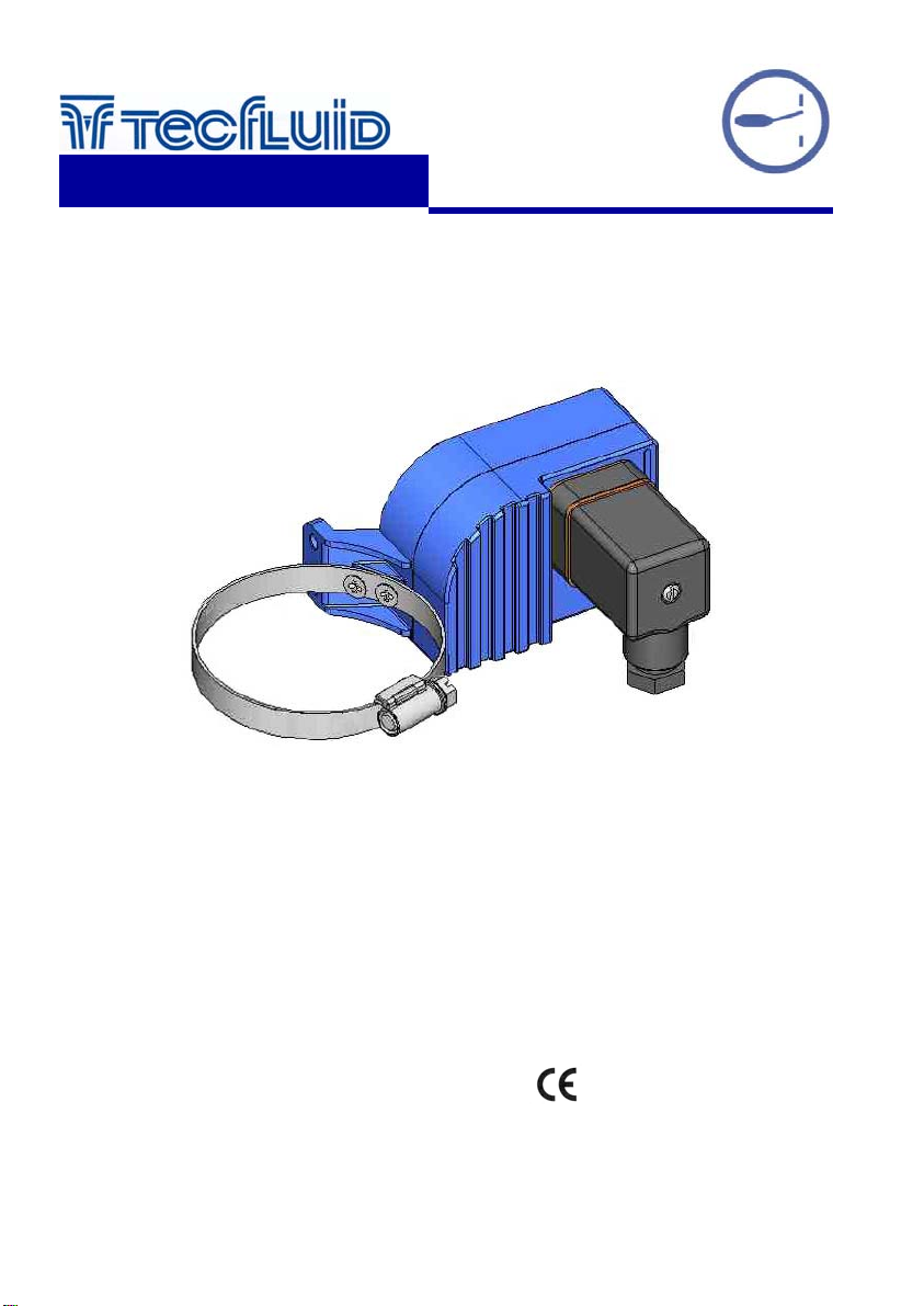
AMM Limit Switch
instrumentation
for fluid s
For Serie LT
Instructions Manual
TECHNICAL DATA
• Material: Housing. Aluminium alloy
• Ambient temperature: -25 to 80 ºC
• Ingress protection: IP65
• DIN 43650-A connector, PG9 cable gland
• Conforms with the Directive 73/23/EEC
C-MI-LTAMM Rev.: 1
English version
Page 2
OPERATION
The level variations in a tank, move the float into the level body.
The float, as it passes by the point where the LT-AMM limit switch is, by means of magnetic
coupling acts on the micro-switch lever changing its position.
The micro-switch position is maintained until the float passes in the opposite direction at the limit
switch position, changing the micro-switch to its original state.
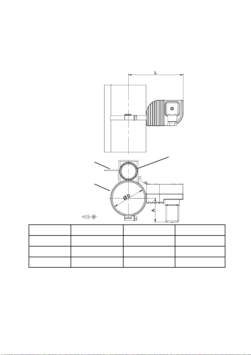
DIMENSIONS
Graduated scale
Float tube
Indicator tube
Model ØD = Ømin ... Ømax Length L Length A
LT-AMM3 23 ... 35 mm 97 mm (for Ø 32) 62 mm (for Ø 32)
LT-AMM6 50 ... 70 mm 110 mm (for Ø 63) 55 mm (for Ø 63)
LT-AMM7 60 ... 80 mm 114 mm (for Ø 73) 50 mm (for Ø 73)
ELECTRICAL CONNECTION
For the electrical installation it is recommended to use multip le conductor c ables with individual
cable sections in the order of 0.25 or 0.5 mm
cables should not be used as they will impair the IP-65 rating of the cable gland.
Before starting the installation, check that the cab le to be used are the right size for the cabl e
gland on the connector, this will guarantee the instrument will stay water tight.
Peel the outside insulation to free the inner ca bles. It is recommended to tin the cables at the
ends of the wires to avoid loose ends which can produce short circuits. Pass the cables through
the cable gland and screw in the cables in their positions. Once the wiring is finished make sure
that the cables are well gripped by the cable gland to maintain the ingress protection degree.
2
2
in order to make it easier to co nnect. Individual
Page 3
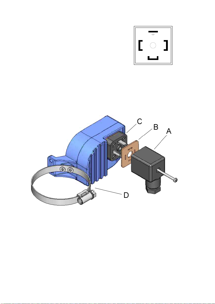
In the female connector (A):
Terminal 1: Common
Terminal 2: NO
Terminal 3: NC
Earth terminal: Earth
Terminal 2 is the normally open contact when the float is
below the level switch.
2
1
3
MOUNTING
Once the electrical connection has been made and the cable gland has been tightened, mount the
female connector (A) on the male base (C), placing the seal (B) between the two pieces.
To fix the level switch in its position on the level, completely unscrew the hose band (D) and open
it. With the hose band open situate the level switch on the float tube and close the hose ban d
over the tube.
Situate the level switch at the required height and tighten the hose band.
Figure 3 Figure 4
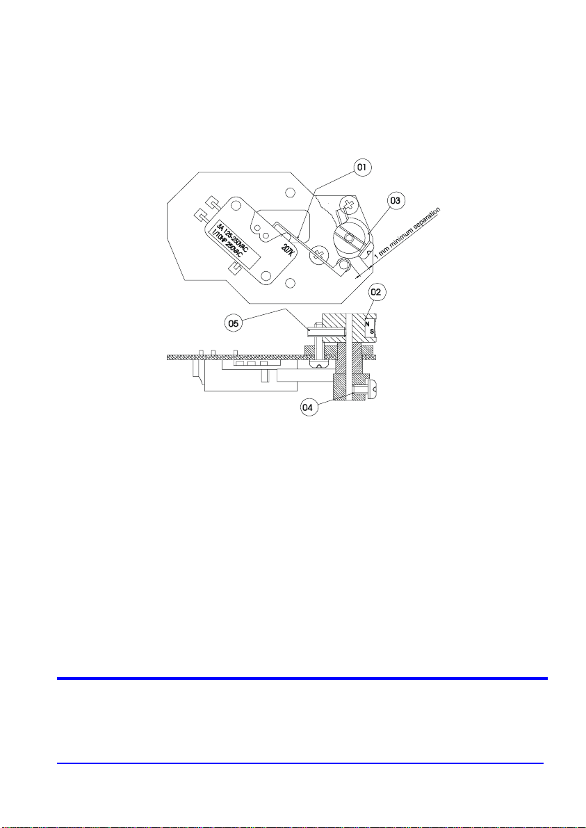
MAINTENANCE (figure of the following page)
Place the limit switch in its normal working position (top figure) and move a magnet in the center of
the hose band (D) as if it was the float. T he magnet should be in a vertical position with the North
pole upwards.
The micro-switch lever (1) has a roller that runs on the cam (3).
To check the operation and correct possible misalignments, do the following:
First open the limit switch housing by removing the four M4 x 25 DIN 7985 screws.
Check that the magnet assembly (2) is firmly fixed to the shaft by the screw (5).
Position the screw (5) as in the drawing (against the stop in a clockwise direction). Position the
cam (3) as in the drawing and tighten the scre w (4). In this position the lever roller should be at
about 1 mm from the screw head (4).
If a multimeter with resistance measurement is available, connect it to terminals 1 & 2 of the
connector base.
3
Page 4
Move the cam (3) slowly in both directions over the whole of its travel.
The multimeter must change from open circuit to short circuit in one direction and vice versa in the
other, when the roller is half way up the eccentric zone of the cam.
When a multimeter is not available, the above can be done by hearin g the “click” when the micro-
switch changes over.
Note: If due to bad handling of the micro-switch lever, the operation is not correct, the microswitch lever (1) should be bent slightly until correct operation is obtained.
WARRANTY
Tecfluid S.A. GUARANTEES ALL ITS PRODUCTS FOR A PERIOD OF 24 MONTHS, after
consignment, against all defects in materials and workmanship.
This warranty does not cover failures which can be imput ed to misuse, use in an appl ication diff erent
to that specified in the order, the result of service or modification by un-authorized persons, bad
handling or accident.
This warranty is limited to cover the repair or replacement defective parts which have not been
damaged by misuse.
This warranty is limited to the repair of the equipment and all further and eventually following
damages are not covered by this warranty.
Any consignment of equipment to our factory or distributor must be previously authorised. The
consignment should be done with the equipment well packed, clean of any liquids, grease or
hazardous materials. Tecfluid S.A. will not accept any responsibility for damage done during
transport.
Together with the equipment, a note should be enclosed indicating the failure observed, the name,
address and telephone number of the sender.
TECFLUID, S.A.
Narcís Monturiol, 33
E-08960 Sant Just Desvern
Tel. + 34 93 3724511 - Fax + 34 93 4734449
E-mail: [email protected]
Internet: www.tecfluid.com
The technical data in this document is subject to modification without notification, if the technical innovations in the product or
manufacturing processes so require.
 Loading...