

Page 1
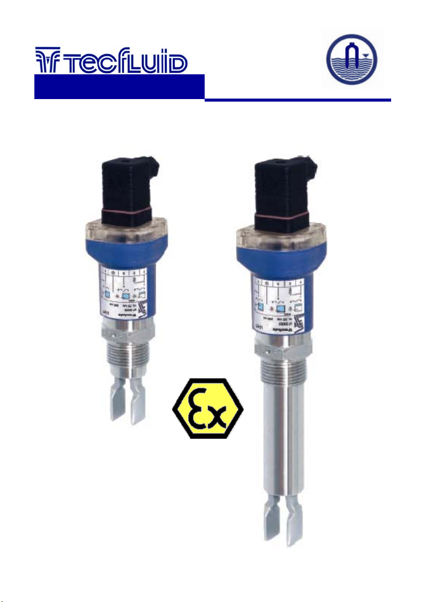
Level switch
LD61N
instrumentation
for fluids
Instructions Manual
R-MI-LD61N Rev.: 0 English Version
Page 2
1. WORKING PRINCIPLE
The LD61N level switch is based on the variation of the natural resonant frequency of a
vibrating fork, when it comes into contact with a liquid.
This variation is detected by the internal electronics and is used to determine the state of
the output .
2. RECEPTION
The LD61N level detectors are supplied ready for installation and operation.
They are supplied packed for their protection during storage and haulage.
To handle the detectors, they should always be held by the head, never by the vibrating
fork.
The vibrating fork should not be modified or bent, as this can damage the detector beyond
repair.
3. INSTALLATION
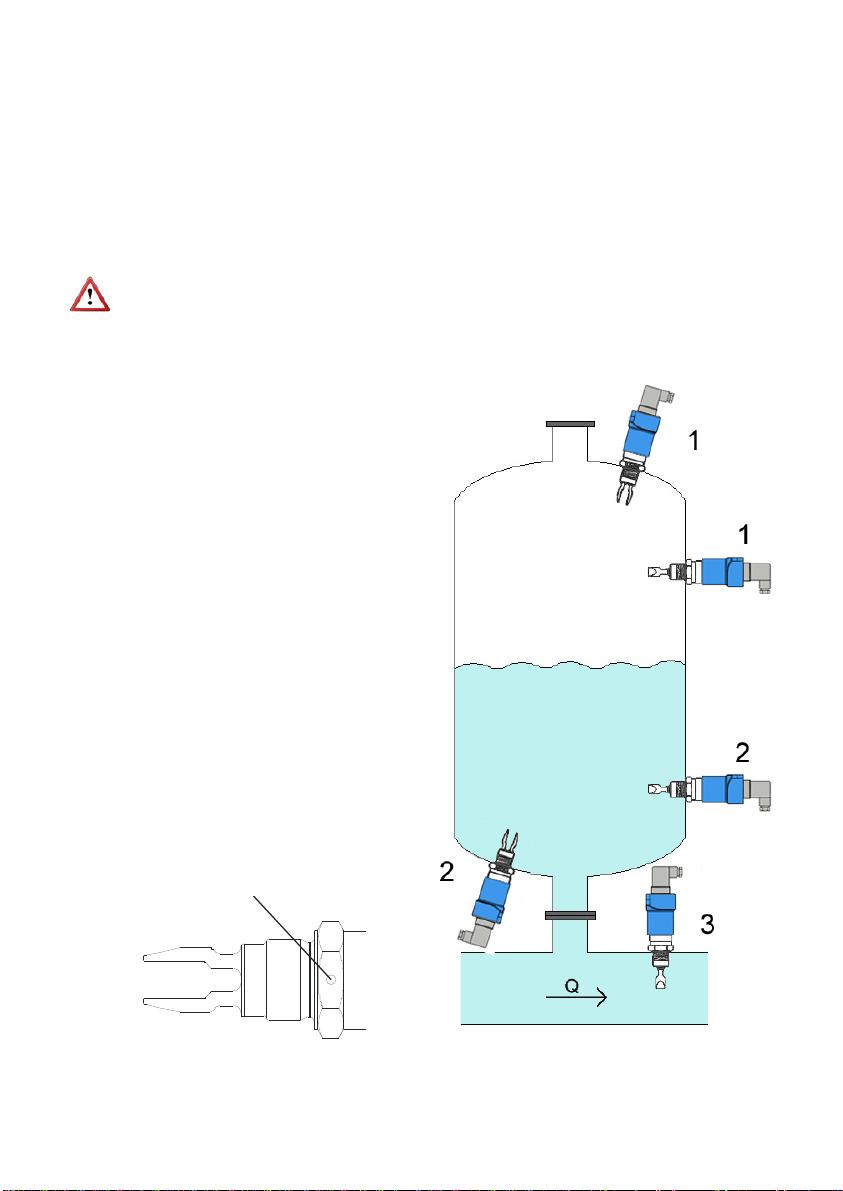
The LD61N level switch can be
mounted in any position. The more
usual insertion points are shown in the
figure 1.
In positions 1 the LD61N acts as a
maximum level detector. In positions 2
the LD61N acts as a minimum level
detector and in position 3 it acts as an
empty pipe detector (for example, to
protect a pump).
If the LD61N is installed in a horizontal
position it is recommended to install it
with the tines vertical to avoid
accumulation of substances, especially
in the case of high viscosity liquids.
To indicate the position of the tines the
LD61N has a round mark on two of the
flats of the nut. These marks should be
in a vertical position when the detector
is installed in a horizontal position.
Punto de
Positioning mark
posicionamiento
Figure 1
2
Page 3
In the same way, when the detector is installed where there is flow, the position must be
a
taken into account. The flat part of the tines must be aligned parallel with the flow direction
as shown in figure 1.
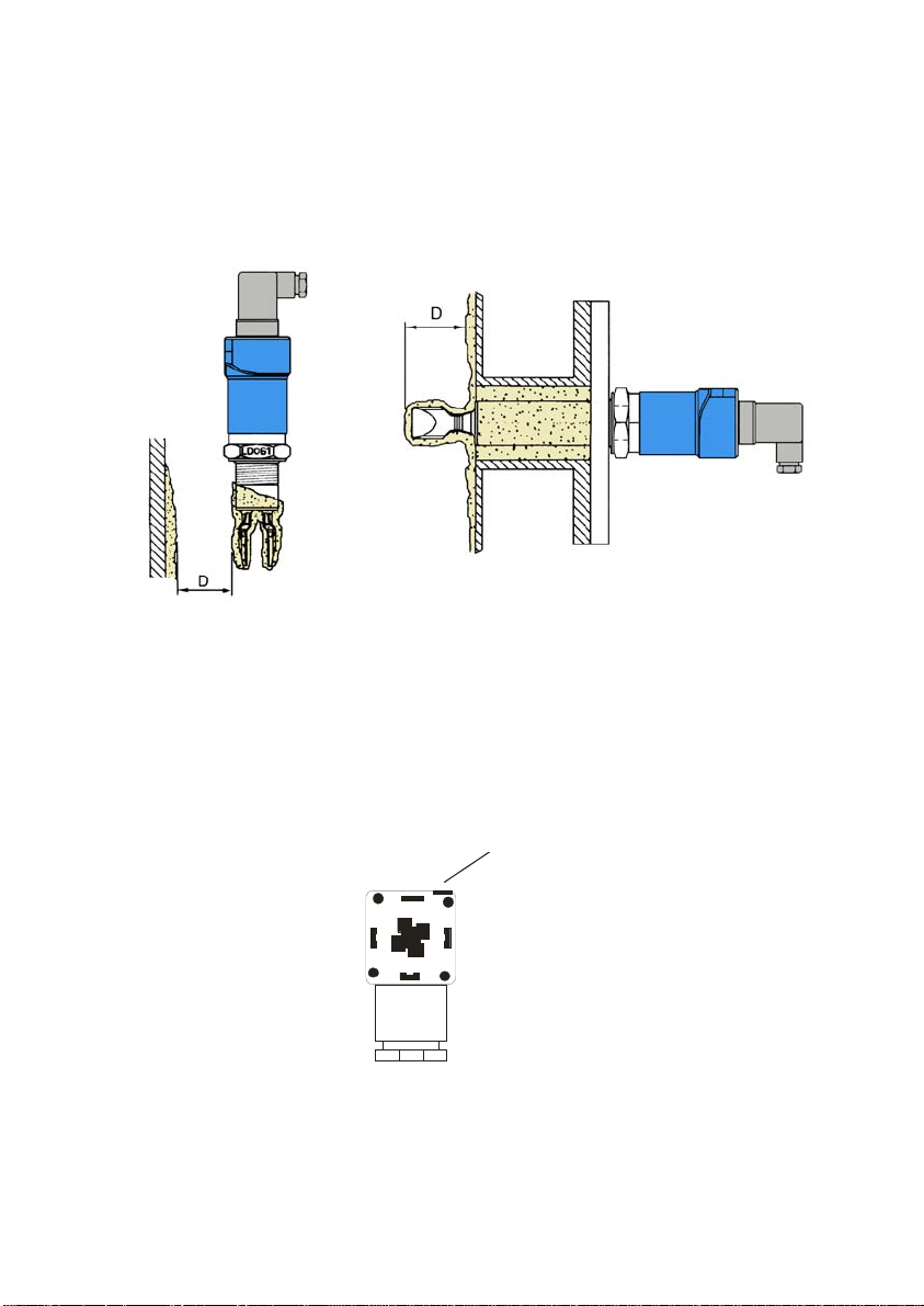
If the viscosity is high, the tines must be kept away from other objects (such as the wall of
the tank). In these cases it is preferable to install a longer detector (figure 2).
The cable gland should be situated on the lower side of the connector. If it is necessary,
the position of the connector can be changed by 90º or 180º. To do this, open the
connector and rotate. This operation must be done with the power disconnected.
Figure 2
4. ELECTRICAL CONNECTION
The LD61N can be installed as a detector of minimum or maximum level. The electrical
connection is made by means of a DIN 43650-A connector with a PG9 cable gland.
Multiple conductor cable with sections about 0,5 mm
2
should be used.
To open the connector, remove the centre screw and prise open using a small
screwdriver in the slot shown in the following drawing (looking at the female connector
from the contact side).
Ranura de apertur
Slot to open the connector
Once the connector is opened, pass the cables through the cable gland and screw in the
cables in their positions, depending on the desired working mode, as explained below.
The working mode (maximum or minimum detection) is given depending on how the
cables are connected (see next page).
3
Page 4
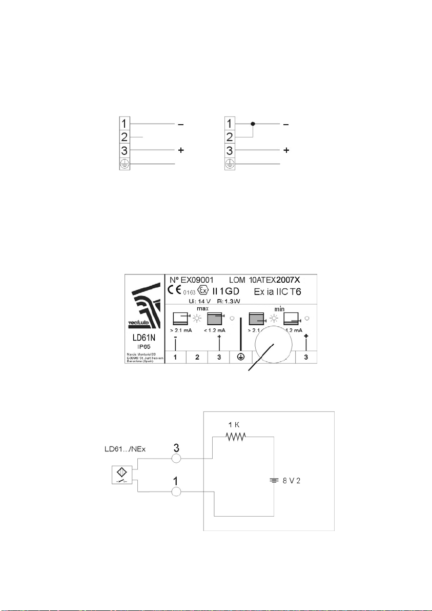
When the LD61N is connected for maximum level detection, the current of the NAMUR
circuit is “high” (> 2.1 mA) when the sensor is not in contact with the fluid (level below the
sensor), and “low” (< 1.2 mA) when the sensor is immersed.
When the LD61N is connected for minimum level detection, the current of the NAMUR
circuit is “high” (> 2.1 mA) when the sensor is in contact with the fluid (level above the
sensor), and “low” (< 1.2 mA) when the sensor is not immersed.
Maximum Minimum
Earth Earth
The LD61N incorporates a LED that indicates the current output state. With the LED ON,
the output current is high (> 2.1 mA).
5. OPERATION TEST
The operation of the installation can be checked by placing a magnet in the zone shown in
the following figure. This magnet will change the output to the opposite state. In this way
the correct installation of the instrument can be checked without having to change the level
in the tank. At the same time, the bi-colour LED will indicate the change of state of the
output.
Test zone
6. OPERATION OF A NAMUR CIRCUIT
Amplifier Circuit
A NAMUR device is a sensor that indicates the different detection states by means of the
current value supplied by an amplifier circuit connected to the NAMUR device.
In addition to being able to indicate the two states ON/OFF (presence/absence of the
physical phenomena to detect), it can indicate alarm states with respect to the device
4
Page 5

operation and the amplifier circuit can detect the state of the connection line to the NAMUR
device.
In the NAMUR LD61N device, the four possible stable states are the following:
1. Open circuit: It occurs when the connection between the amplifier circuit and the
NAMUR device is broken. The output current of the amplifier circuit will be equal or
less than 0.05 mA.
2. OFF state of the NAMUR device: The output current of the amplifier circuit will be
from 0.35 mA to 1.2 mA.
3. ON state of the NAMUR device: The output current of the amplifier circuit will be
from 2.1 mA to 6.03 mA.
4. Short circuit: It occurs when there is a short circuit in the connection between the
amplifier circuit and the NAMUR device. The output current of the amplifier circuit will
be more than 7.45 mA. The resistance between terminals will be less than 100
Ohms.
NOTE: the current values are calculated by using a nominal voltage value of 8.2V and an
amplifier output resistance of 1k, and the limits for the resistance between terminals
specified in the standard (from 100 to 360 Ohms).
6. MAINTENANCE
The working life of the vibrating fork depends basically on the abrasive characteristics of
the product used.
The LD61N detector only needs maintenance when the product, which can adhere to the
tines, will not let the detector change to a non detection state. In these cases the tines
must be cleaned.
6.1 Cleaning
To clean the tines, a brush suitable for removing the incrusted product must be used. You
should not try to knock off the adhered product from the tines.
During the cleaning process, be careful not to apply force against the tines as this can
bend them and damage the detector beyond repair.
7. TECHNICAL CHARACTERISTICS
Materials: Fork: EN 1.4404 (AISI 316L). Others on demand.
Housing: Polycarbonate.
Process connection:
Threads G1 (BSP), 1” NPT, DIN 11851, Clamp ISO 2852
Model: NAMUR (IEC60947-5-6, EN50227)
Switching time: ≈ 1s
Hysteresis
: ± 2 mm with H
O
2
Operation limits: Viscosity: up to 10.000 cSt
Density: > 0.6 kg / l
Process temperature (liquid). -30 ... 115ºC
Ambient temperature: -5 ... 40ºC
Standard pressure: PN25
Ingress Protection: IP65
5
Page 6
Power supply:
Minimum voltage:
Maximum voltage: 14 VDC
Consumption: From
Conforms with the 2006/95/CE Directive
Conforms with the 2002/96/CE Directive
Conforms with the 2004/108/CE Directive
Conforms with the 97/23/CE Directive
Conforms with the 94/9/CE Directive
This equipment is considered as being a pressure accessory and NOT a safety
accessory as defined in the 97/23/CE directive, Article 1, paragraph 2.1.3.
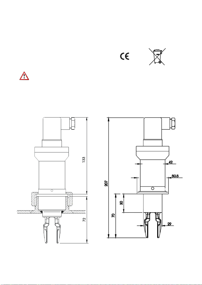
Dimensions:
TF DIN405 Rd52x1/6 Clamp (ISO 2852)
8 VDC
0.7 mA to 2.3 mA, depending on the state “ON/OFF”
6
Page 7
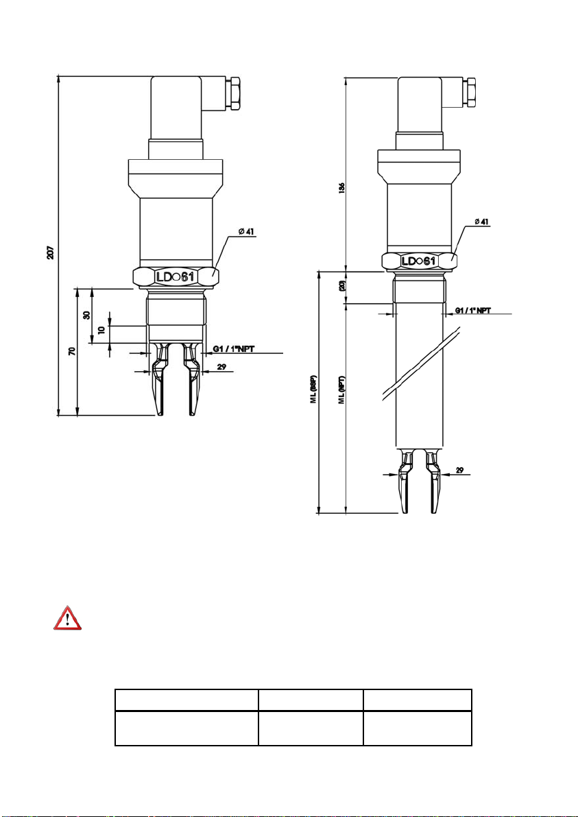
G1 or 1” NPT thread LD61N ML
7.1 Safety characteristics
Given that this instrument is group II, it is intended for use in places likely to become
endangered by explosive atmospheres, but not in mines. The category is 1G, that is, it is
intended for use in areas in which explosive atmospheres caused by mixtures of air and
gases, vapours or mists are present continuously, for long periods or frequently.
NOTE: This instrument can not be installed in places with impact risk. Special caution
should be exercised in the installation and use to prevent any impact or fall of the device.
7.2 Exi parameters
Specific parameters Ui : 14 V
Marking Ex ia IIC T4 Ex ia IIC T6
Pi : 1.3 W
Ui : 14 V
Pi : 1.3 W
7
Page 8
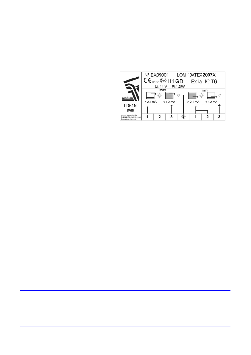
8. MARKING
The marking of the equipment shows the following characteristics:
- Manufacturer
- Model
- Serial number (year of construction and number)
- CE marking
- Intrinsic safety marking
- Notified body
- Electrical parameters
- Manufacturer address
WARRANTY
Tecfluid S.A. GUARANTEES ALL ITS PRODUCTS FOR A PERIOD OF 24 MONTHS, after
consignment, against all defects in materials and workmanship.
This warranty does not cover failures which can be imputed to misuse, use in an application different
to that specified in the order, the result of service or modification by un-authorized persons, bad
handling or accident.
This warranty is limited to cover the repair or replacement defective parts which have not been
damaged by misuse.
This warranty is limited to the repair of the equipment and all further and eventually following
damages are not covered by this warranty.
Any consignment of equipment to our factory or distributor must be previously authorised. The
consignment should be done with the equipment well packed, clean of any liquids, grease or
hazardous materials. Tecfluid S.A. will not accept any responsibility for damage done during
transport.
Together with the equipment, a note should be enclosed indicating the failure observed, the name,
address and telephone number of the sender.
SHIPPING
In the event of damages during shipping, claim directly to the carrier over a period of less than 24
hours. Tecfluid is not responsible for any damage caused during the shipment of material.
TECFLUID, S.A.
Narcís Monturiol, 33
E-08960 Sant Just Desvern
Tel. + 34 93 3724511 - Fax + 34 93 4734449
E-mail: [email protected]
Internet: www.tecfluid.com
The technical data in this pamphlet is subject to modification without notification, if the technical innovations in the product or
manufacturing processes so require.
 Loading...