

Page 1
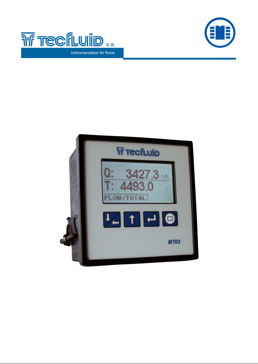
Electronic converter
for flowmeters
MT03F
Instructions manual
R-MI-MT03F Rev.: 0 English version
Page 2

PREFACE
Thank you for choosing the MT03F converter from MT03 series of
Tecfluid S.A.
This instruction manual allows the installation, programming and
operation of the MT03F converter. It is recommended to read it
before using the equipment.
WARNINGS
This document shall not be copied or disclosed in whole or in
any part by any means, without the written permission of
Tecfluid S.A.
Tecfluid S.A. reserves the right to make changes as deemed
necessary at any time and without notice, in order to improve
the quality and safety, with no obligation to update this manual.
Make sure this manual goes to the end user.
Keep this manual in a place where you can find it when you
need it.
In case of loss, ask for a new manual or download it directly
from our website www.tecfluid.com Downloads section.
Any deviation from the procedures described in this instruction
manual, may cause user safety risks, damage of the unit or
cause errors in the equipment performance.
Do not modify the equipment without permission. Tecfluid S.A.
is not responsible for any problems caused by a change not
allowed. If you need to modify the equipment for any reason,
please contact us in advance.
2
Page 3

TABLE OF CONTENTS
1 INTRODUCTION ................................................................................... 5
2 RECEPTION .......................................................................................... 5
2.1 Storage temperature ................................................................ 5
3 INSTALLATION .................................................................................... 5
3.1 Location .................................................................................... 5
3.2 Electrical connection ............................................................... 6
3.2.1 Power supply wiring .................................................. 6
3.2.2 Pulse input wiring ...................................................... 7
3.2.3 Pickup (turbine) input wiring .................................... 8
3.2.4 Pulse output wiring ..................................................... 9
3.2.5 Analog output wiring ................................................. 10
3.2.6 Relay output wiring .................................................... 11
3.2.7 Remote reset input wiring ......................................... 12
4 OPERATION ......................................................................................... 13
5 MAIN MENU .......................................................................................... 14
5.1 Passwords to access the menus ............................................ 14
6 INSTALLATION PARAMETERS .......................................................... 16
6.1 Language .................................................................................. 17
6.2 K factor ...................................................................................... 17
6.3 Density ...................................................................................... 17
6.4 Input ....................................................................................... 18
6.5 Analog filter ............................................................................... 18
6.6 Diagnosis .................................................................................. 18
7 PROGRAMMING PARAMETERS ........................................................ 19
7.1 Language .................................................................................. 20
7.2 Flow rate units .......................................................................... 20
7.3 Totalizer units ........................................................................... 21
7.4 Flow rate decimals ................................................................... 21
7.5 Flow rate ................................................................................... 21
7.5.1 Cut off .......................................................................... 22
7.5.2 Damping ...................................................................... 22
3
Page 4

7.6 Outputs ..................................................................................... 22
7.6.1 Relay 1 and relay 2 ..................................................... 23
7.6.1.1 Batching ...................................................... 23
7.6.1.2 Alarm ............................................................ 23
7.6.1.3 Deactivation ................................................ 24
7.6.2 Analog output ............................................................. 24
7.6.2.1 Programming of the 4-20 mA output ......... 24
7.6.2.2 Current calibration for 4 and 20 mA ......... 24
7.7 Default screen .......................................................................... 25
8 TOTALIZER ........................................................................................... 26
9 SERIAL NUMBER ................................................................................. 26
10 SOFTWARE VERSION ......................................................................... 26
11 BRIGHTNESS ....................................................................................... 26
12 BATCHING ............................................................................................ 26
12.1 Batching start ........................................................................... 27
12.2 Process and end of batching .................................................. 27
13 WORKING SCREEN ............................................................................. 28
14 MAINTENANCE .................................................................................... 28
14.1 Fuse ........................................................................................... 28
15 MEASUREMENT ERROR CORRECTIONS ......................................... 28
16 ASSOCIATED SOFTWARE WINSMETER MT03 ................................ 29
16.1 USB cable connection and drivers installation ..................... 29
16.2 Port connection ........................................................................ 30
16.3 Access to installation and programming ............................... 31
16.4 Visualization ............................................................................. 33
16.5 Graphic ...................................................................................... 34
16.6 Datalogger ................................................................................ 35
16.7 Firmware update ...................................................................... 36
17 TECHNICAL CHARACTERISTICS ....................................................... 37
18 DIMENSIONS ........................................................................................ 38
19 TROUBLESHOOTING .......................................................................... 39
4
Page 5
1 INTRODUCTION
MT03F converters are flow rate indicators, totalizers and controllers for batching
processes.
The electronic circuit is based on the most advanced technology in digital signal
processing, in order to obtain accurate and reliable measurements.
The equipment provides the following features (depending on the model):
Graphic display with intuitive menus.
Pulse input compatible with oscillating piston flowmeters series COVOL and
turbine flowmeters series TM, as well as with most of existing pulse transmitters
on the market.
Volume preset and relay outputs for batching processes.
Flow rate, totalizer and accumulated total indication.
Pulse output (input signal repeater).
Current output (4-20 mA) proportional to the flow rate and user programmable.
Relay outputs user programmable as flow rate alarm.
2 RECEPTION
The MT03F converters are supplied conveniently packaged for transportation together
with their instruction manual for installation and operation.
All devices have been verified in our facilities.
2.1 Storage temperature
-20ºC ...... +60ºC
3 INSTALLATION
3.1 Location
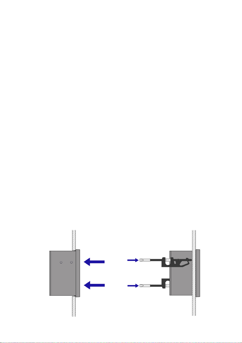
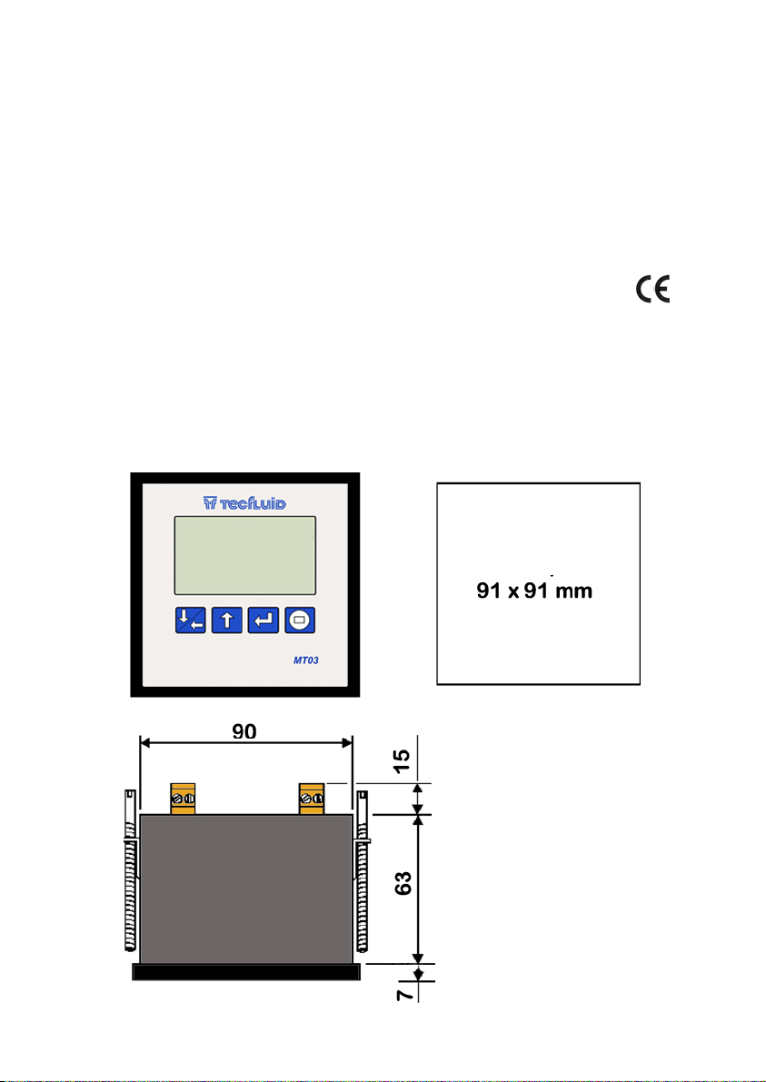
The MT03F converter is housed in a box according to IEC 61554 standard. Its size is 96x96
mm and is intended to be mounted on a panel of a cabinet with a square hole of 90 x 90 mm
+0.5 mm / -0 mm. The cabinet should have a minimum depth of 90 mm behind the panel.
To place it into the cabinet, slide it through the front panel to the bottom as shown in the
following figure. Then screw the clamping arms until exert pressure on the panel.
5
Page 6
3.2 Electrical connection
The connection of the equipment is via plug-in connectors, polarized to avoid mistakes
when plugged in. The connectors have screw terminals, as per VDE standards, to accept
cables with section of 1.5 mm
2
.
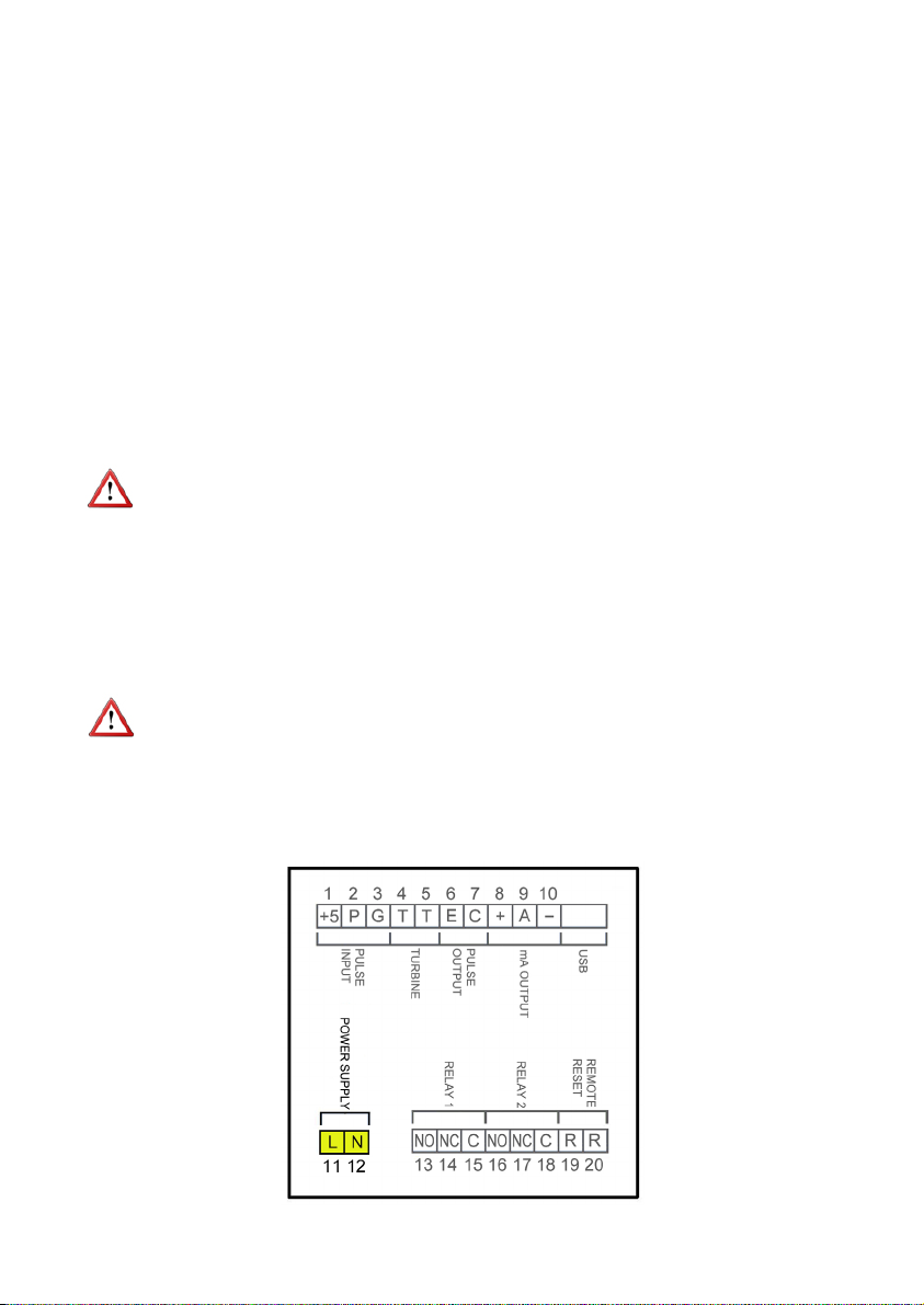
The pictures of the connections in this manual are always looking the equipment from the
back.
To help in the wiring of the equipment, the description of the terminals is marked on a
label in the rear side of the device..
For the electrical installation it is recommended to use multiple conductor cables with
individual cable sections in the order of 0.25 to 0.5 mm
2
in order to make it easier to
connect. It is better to maintain the cables with mains voltage (power supply) separated
from the cables with low level signals (4-20 mA, etc.).
To connect the cables, peel the outside insulation to free the inner cables. It is
recommended to put a terminal at the ends of the wires to avoid loose ends.
Then, screw the wires into the corresponding positions in the female aerial connector.
Finally, place each connector with its corresponding male connector on the rear side of
the converter.
IMPORTANT NOTE: In order to comply with the electrical safety requirements as per EN61010-1 (IEC 1010-1), the installation of the equipment must take into account the
following:
The equipment must be installed in the front panel of an electrical mounting
cabinet, leaving only the front of the equipment accessible to the operator.
In case of AC power supply, a mains switch must be provided to disconnect the
equipment. This switch must be marked as the disconnecting device for the
equipment and be within easy reach of the operator.
The housing must not be opened when the instrument has mains supply
connected.
IMPORTANT NOTE: To ensure a right operation of the equipment, it is recommended to
make the connection paying attention to the following points:
For the output signals, use shielded cable when possible.
Keep the cables away from strong sources of noise.
3.2.1 Power supply wiring
6
Page 7
Before starting the wiring of the instrument, check that the supply voltage available is the
same as marked on the label of the converter.
Terminal Power supply AC Power supply DC
11 Phase DC
12 Neutral DC
In case of DC power supply, the equipment is provided by a diode bridge that allows
connecting it regardless of the polarity .
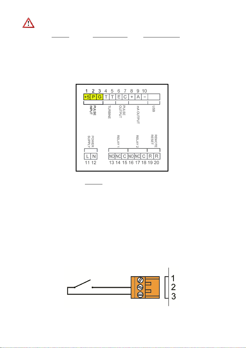
3.2.2 Pulse input wiring
Terminal
1 Voltage output +5V
2 Contact
3 Ground
This input is compatible with all oscillating piston flowmeters series COVOL, as well as
with instruments that provide an output of the following types:
- From 0 to VCC, where VCC = 5 … 24V
- NPN open collector
- Free potential contact
For those devices requiring be powered to 5VDC to generate output pulses, the MT03F
have this supply voltage in Terminal 1.
Free potential contact
7
Page 8
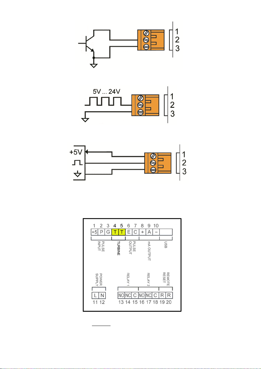
5V … 24V pulses
3.2.3 Pickup (turbine) input wiring
Open collector
5V power supply
Terminal
4 Turbine
5 Turbine
8
Page 9
This input is compatible with all turbine flowmeters series TM and those instruments that
provide a magnetic pickup type output whose voltage is between 30 mVpp and 10 Vpp.
Higher values can damage the equipment.
The input impedance is 2 k. It has a protection for limiting the voltage applied to the
circuit consisting of two diodes in parallel and two 100 resistors.
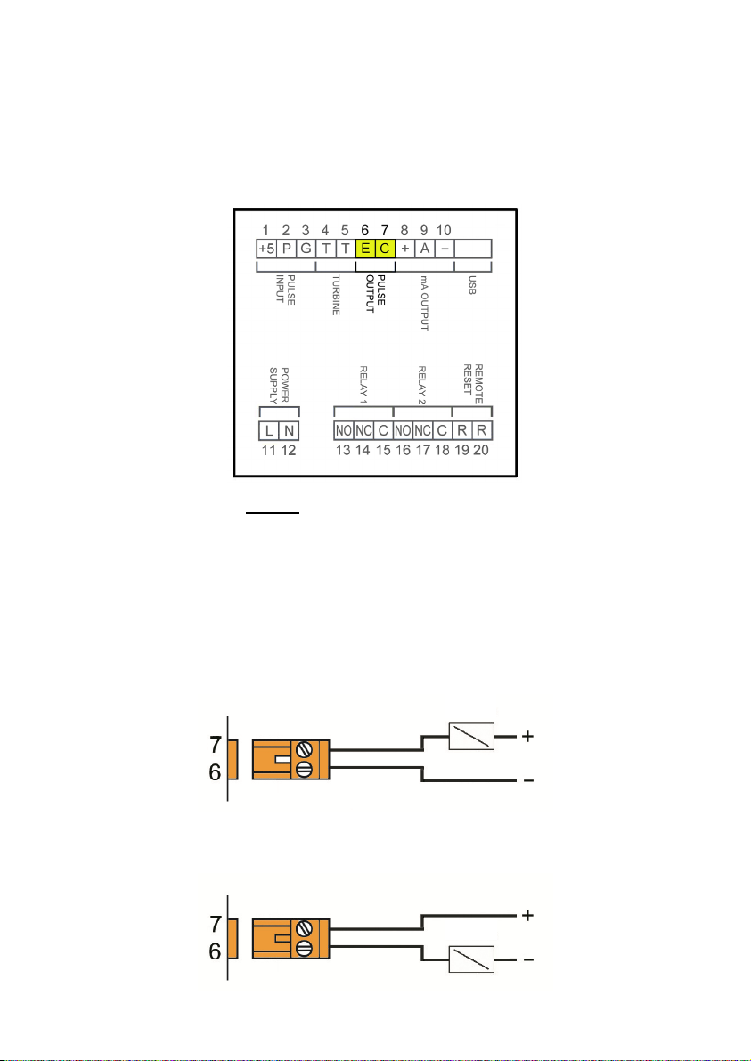
3.2.4 Pulse output wiring
Terminal
6 Emitter
7 Collector
The pulse output operates in repeater mode. It gives a pulse for every input pulse or for
each turbine signal period.
The pulse output is opto-isolated. The terminals are the collector and emitter of a NPN
bipolar transistor.
Example. Connection with the load at the collector
Example. Connection with the load at the emitter
9
LOAD
LOAD
Page 10
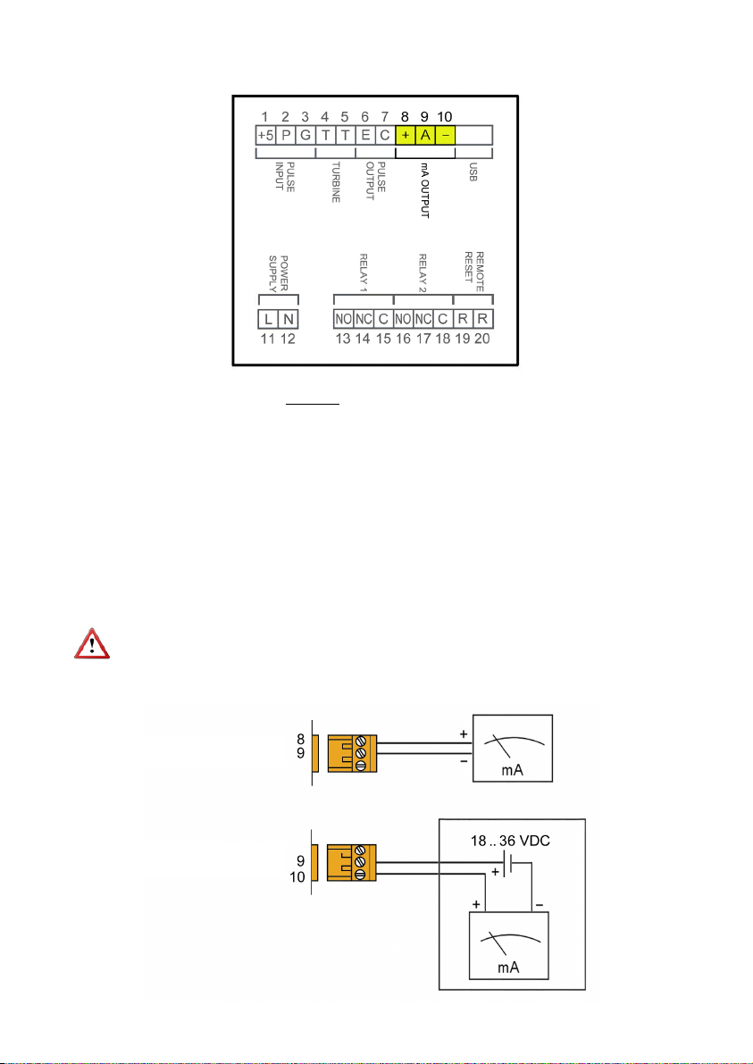
3.2.5 Analog output wiring
Terminal
8 mA (positive, active output)
9 mA
10 mA (negative, passive output)
The analog output is galvanically isolated. It can be either active (which means that the
receiving device must be passive) or passive (which means that the receiver must supply
the power for the current loop). It is recommended to use a receptor with an input
resistance of less than 700 to guarantee correct operation.
The configuration of the analog output mode (active or passive) is done by means of the
connection to the terminal strip. For active mode, terminals 8 and 9 are connected. For
passive mode, terminals 9 and 10 are connected.
NOTE: The analog output has protection against reversed polarity. Due to another
protection against over voltages, if a loop supply voltage of more than 32 V is connected
the equipment may be damaged.
Active output
Passive output
10
Page 11
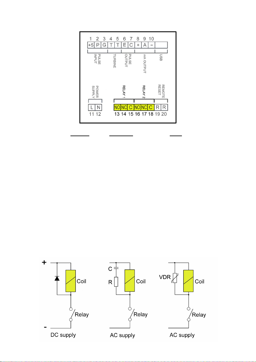
3.2.6 Relay output wiring
Terminal Description Relay
13 Normally open Relay 1
14 Normally closed Relay 1
15 Common Relay 1
16 Normally open Relay 2
17 Normally closed Relay 2
18 Common Relay 2
The relay outputs provide relays with potential free contacts (see characteristics on page
37).
The status of the relay contacts corresponds to the relay at rest.
The relay contacts are not protected in any way, and therefore they must be installed
externally as required in the application, taking into account the limitations of the
characteristics of such contacts.
In the case of having inductive loads, and to extend the working life of the relay contacts,
it is recommended to use overvoltage protection (VDR for AC and diodes for DC loads).
In all cases a fuse or some kind of protection against short circuits should always be
provided according to the needs of the intended load.
11
Page 12
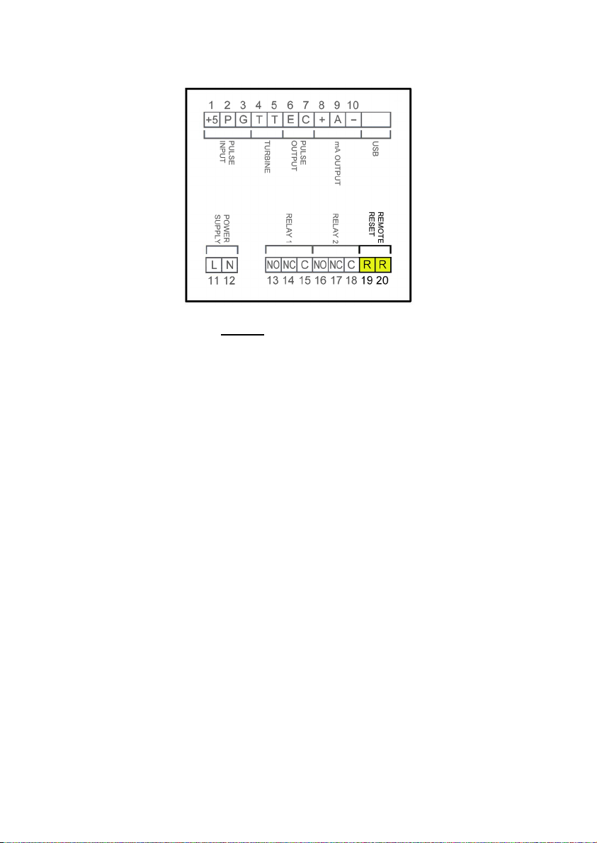
3.2.7 Remote reset input wiring
Terminal
19 Contact
20 Contact
These terminals correspond to an input that starts a batching process. A potential free
normally open push button can be connected. The push button contact must be a good
quality snap action switch to guarantee correct working at low voltages and reduce contact
bounce effects.
12
Page 13
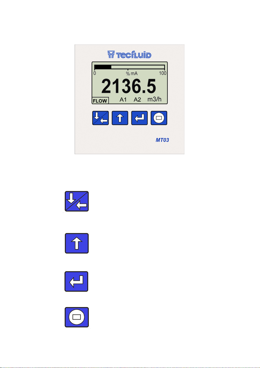
4 OPERATION
The MT03F converters have a graphic LCD and a keyboard with 4 push buttons.
The following figure shows the functionality of the converter keys.
(Down / Left) To enter the preset values
for a batching.
To switch between flow rate, totalizer
and fluid velocity screens.
To change to the digit on the left.
Into the menu, to scroll down.
(Up) To switch between the different
screens. To change the decimal point.
To increase the digit.
Into the menu, to scroll up.
(Enter) To validate the data.
To enter into installation and
programming modes of the converter.
To exit from an informative text.
(Escape) To start a batching process.
To return to the previous menu. To exit
from a screen without validating data.
13
Page 14
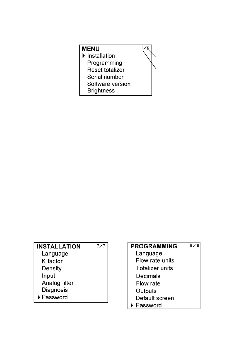
5 MAIN MENU
To access the main menu of the converter, press the key (Enter). The following screen
appears:
Number of menu items
Selected item
The "Installation" option allows the basic configuration of the instrument, as explained in
Chapter 6 of this manual.
The "Programming" option allows to program all parameters of the converter, as
explained in Chapter 7 of this manual.
From the "Reset totalizer" option, the user can return the totalizer to zero. When exiting
the menu, the totalizer will begin to accumulate again.
Note: The “Reset totalizer” operation requires the program password input (see section
5.1).
The options "Software Version" and "Serial Number" are informative and are discussed in
Chapters 9 and 10 of this manual.
5.1 Passwords to access the menus
The password for the installation menu may be different from the password for the
program menu.
By default, the equipment is factory configured with the password disabled.
If you want to change any of these passwords, you must enter the corresponding menu
and once inside, access the submenu "Password".
To change the access password of
the installation menu, select
"Installation" on the main menu and
then "Password".
To change the access password of
the programming menu, select
"Programming" in the main menu
and then "Password".
14
Page 15
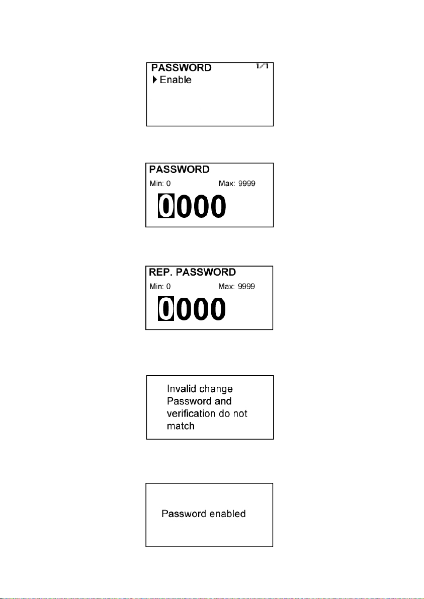
When the "Password" option is selected, a screen that indicates the password status for
this menu appears.
Selecting “enable”, the screen to enter the new password appears.
Once entered, the new password is asked again to avoid possible inadvertent error.
If the re-entered password does not match the first one, the following error message
appears and the process should be carried out again.
If both passwords match, the following information message is displayed:
15
Page 16
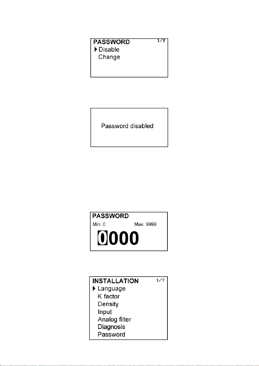
If the password needs to be changed or disabled, the procedure is the same. Once
entered the "Password" menu, the following screen appears:
If change is selected, the equipment will ask for a password again. If Disable is selected,
the following message will appear:
6 INSTALLATION PARAMETERS
Power on the electronic converter with the voltage indicated on the label.
Press the (Enter) key in order to enter the main menu.
With the keys (Down / Left) and (Up), select “Installation”, and then validate with the key
(Enter).
If the converter has the password option enabled, a password must be entered. For more
details about the password see section 5.1 on page 14.
Once in the installation menu, the first screen allows to choose between the different
options.
16
Page 17
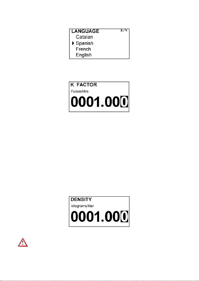
6.1 Language
You can choose the language in which all the menus will be displayed.
6.2 K factor
In this screen the K factor from the pulse transmitter (COVOL, TM44 or other) must be entered.
This value should be found on the label of the counter or turbine.
The introduction of numerical values is performed as follows:
By default, the value to enter has 4 digits and 3 decimals.
Although for most cases with this format is enough, if the location of the decimal point is
needed to be changed, for example to have 5 integers and 2 decimals, the method for
doing this is the following:
- Scroll to the number where the decimal point will be placed
- Press the key (Up) and hold (about 3 seconds) until the decimal point change to the
desired position.
- Enter the desired numerical value using the keys (Lower / Left) and (Up).
If this operation is performed on the least significant digit (first from right), the decimal
point will disappear and will have 8 integers to enter the numeric value.
6.3 Density
If an indication of mass flow rate is preferred, density value of the liquid can be entered in
kg / liter.
Measurement units are selected in the programming menu (see page 20).
NOTE: The change in density value affects only the mass flow rate indication and mass
totalization, when the corresponding units are selected.
17
Page 18
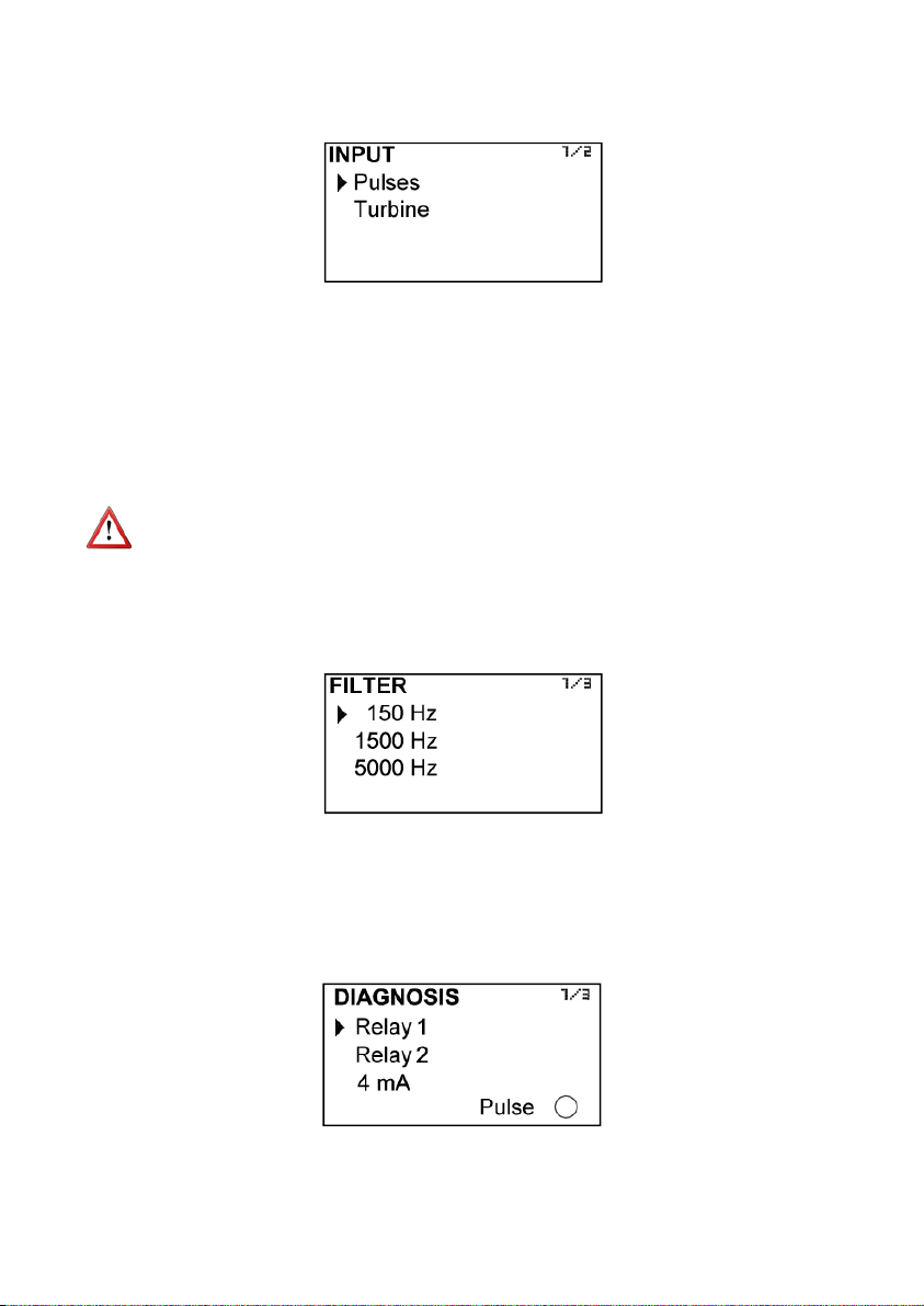
6.4 Input
In this screen the type of signal from the sensor connected to the MT03F can be chosen.
Pulse input is compatible with all flowmeters series COVOL, and with any instrument that
has an pulse output of one of the following types:
- De 0 a VCC, where VCC < 24V
- NPN open collector
- Potential free contact
Turbine input is compatible with all turbines series TM and with any instrument that has a
pickup type output with a voltage between 30 mVpp and 10 Vpp.
IMPORTANT NOTE: If the input pulse is chosen, the associated sensor must be
connected to terminals 1, 2 and 3, as indicated in section 3.2.2 on page 7. In the same
way, if turbine input is selected, the connection must performed at terminals 4 and 5 as in
section 3.2.3 on page 8.
6.5 Analog filter
The input signal can be filtered in order to cancel high frequency non desired signals.
For flowmeters series COVOL, a selection of 150 Hz filter is recommended.
For turbine flowmeters series TM, a selection of 1500 Hz filter is recommended.
6.6 Diagnosis
It allows to check some parameters of the equipment.
18
Page 19
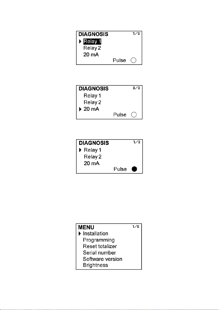
Pressing the key (Enter) while selecting Relay 1 or Relay 2 will activate or deactivate this
output. When the relay is ON, the word is shown in reverse text.
If 4mA is selected, pressing the key (Enter) toggles between 4, 8, 12, 16 and 20 mA,
allowing to check the adjustment of the analog output.
In either case, the circle next to the word "Pulse" is shown in black every time the equipment
receives a pulse.
NOTE: To make the diagnosis of pulse input the frequency should be less than 2 Hz.
7 PROGRAMMING PARAMETERS
By programming the converter the visualization and the outputs of the instrument can be
configured.
Turn on the converter and press (Enter) to enter the main menu. The following screen
appears:
19
Page 20
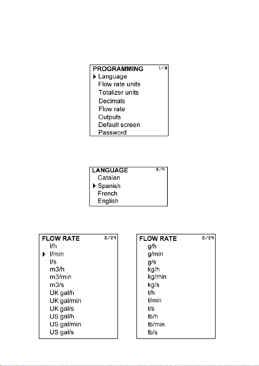
With the keys (Down / Left) and (Up), select Programming, and then validate with the key
(Enter).
If the converter has the password option enabled, a password must be entered. For more
details about the password,, see section 5.1 on page 14.
Once in the programming menu, the first screen allows to choose between the different
options.
7.1 Language
You can choose the language in which all the menus will be displayed.
7.2 Flow rate units
In this screen the units for the flow rate indication can be chosen.
20
Page 21
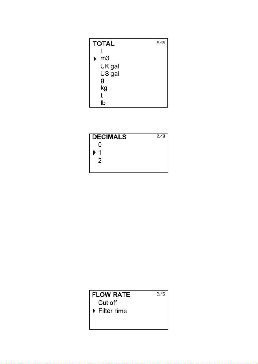
7.3 Totalizer units
The units for the totalizer and accumulated total can be chosen.
7.4 Flow rate decimals
In this screen the number of decimals for the flow rate indication can be selected.
To select the number of decimals it must be taken into account that the instrument has 5
digits for flow rate indication. If two decimals have been selected, these will be seen whilst
the flow rate is not higher than 999.99. Above this value the indication will automatically
change to one decimal, and when the flow rate is higher than 9999.9 the indication will be
done without decimals.
If one decimal is selected, the flow rate indication will have a maximum of one decimal
until 9999.9. Above this value the indication will be done without decimals.
If indication without decimals is selected, the flow rate will always be shown without
decimals.
For the selection of the flow rate units and the number of decimals it must be taken into
account that an indication with an excess of decimals may give the sensation of instability
of the reading. As a general rule it can be considered that the reading should not have
more than a total of 5 digits (integer + decimals).
7.5 Flow rate
This screen displays a submenu to modify different aspects related to flow reading, such
as cut off and filtering.
21
Page 22
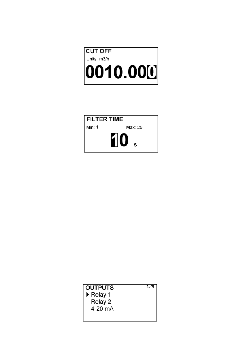
7.5.1 Cut off
A cut off flow rate can be programmed, that means, the flow rate below which the flow
rate indication will be zero. This can avoid reading errors in the lower zone of the working
range.
7.5.2 Damping
The converter has an adaptive filter (damping) to provide stable flow rate and analog
output readings in the presence of continuous flow rate fluctuations.
The configuration of this filter can be very useful in the cases where the flow rate readings
have some instability (due to air bubbles, solids in suspension, etc).
Only the flow rate indication of the display and the analog output are affected by the filter.
The relay output and the totalizer act according to the instant flow rate. Selecting a filter
with a longer or shorter integration time will provide more or less stable readings and will
also affect the response time to small variations of flow rate.
The integration time is selected in seconds, with a minimum value of 0 and a maximum
value of 25 seconds. For example, with an integration time of 15 seconds, the display will
indicate the flow rate reading of the average flow rate over the last 15 seconds from the last
update of the display. This does not mean that the display is refreshing its data every 15
seconds. The display shows a new value several times per second, indicating an average
of the flow rate values of the last 15 seconds.
When there is a sudden variation of the flow rate then the filter should react as fast as
possible to give a correct reading of the new value. For this, the filter controls the deviation
of the instant flow rate with respect to a reference for each reading. If this deviation
exceeds the 25%, the filter will stop acting, indicating the instant value, and will start again
the filtering process.
7.6 Outputs
This screen allows to program the three outputs of the instrument: Relay 1, Relay 2 and
analog output (4-20 mA).
22
Page 23
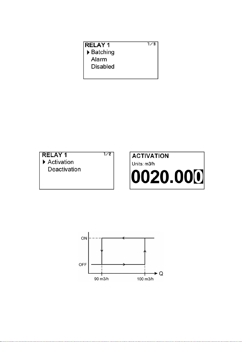
7.6.1 Relay 1 and relay 2
By selecting one of the two relay outputs, next screen appears with the options which
allow to assign the relay to a function.
7.6.1.1 Batching
If batching option is selected, the relay will change its state at the start or end of a
batching process.
For detailed information about batching, see section 12 on page 26
7.6.1.2 Alarm
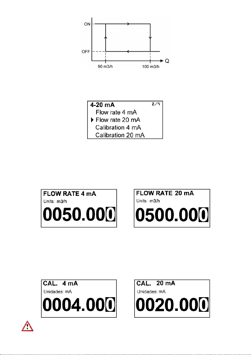
If Alarm is selected, we have access to program the flow rate at which the relays will
change its status and to the level of hysteresis. By level of hysteresis we understand the
difference between activation and deactivation of the output. To avoid that an alarm
output is continuously moving from activate to deactivate status, we must program the
points of connection and disconnection.
Example 1
If the activation point is programmed to 100 m
programmed to 90 m
the flow rate reaches a value of 100 m
below 90 m
3
/h.
3
/h, when the flow rate is zero the output will be deactivated. When
3
/h the output will be activated until the level falls
3
/h and the deactivation point is
Example 2
If we program an activation point of 90 m
the level is zero the output will be activated. When the flow rate reaches a value of 100
3
/h the output will be deactivated until the flow rate falls below 90 m3/h.
m
3
/h and a deactivation point of 100 m3/h, when
23
Page 24
7.6.1.3 Deactivation
The relay will be always at rest.
7.6.2 Analog output
The flow rate corresponding to 4 mA and 20 mA can be programmed and the calibration
for these two values can be made as well.
7.6.2.1 Programming of the 4-20 mA output
Flow rate values equivalent to each current are entered directly.
The flow rate programmed for 20 mA must be higher than the programmed for 4 mA.
Otherwise, the current loop will always give 4 mA.
7.6.2.2 Current calibration for 4 and 20 mA
The MT03F converter is delivered with the current output already calibrated. If you want to
correct a derive of the 4 or 20 mA current values because they do not coincide with the
ammeter used, it can be done by entering de ammeter value and pressing the key
(Enter). The ammeter will adjust its value and the MT03F screen will show the values of 4
or 20 mA again in the event the operation needs to be done again. More than one
adjustment can be necessary to do a complete calibration.
Before making a current calibration, be sure that the ammeter used for that is showing a
correct value.
24
Page 25
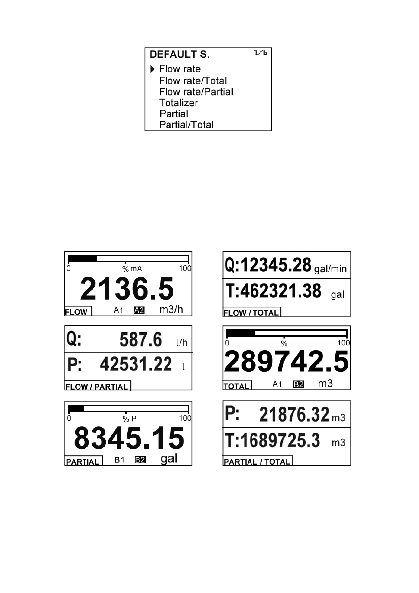
7.7 Default screen
The converter presents the selected screen when a power failure occurs.
the following default screens can be programmed:
- Flow rate
- Flow rate + Totalizer
- Flow rate + Accumulated total
- Totalizer
- Accumulated total
- Accumulated total + Totalizer
The first three screens show the relay output status, if they are activated.
If the relay is in alarm mode, an “A” will appear in normal or inverse format depending on
the relay status.
If the relay is in batching mode, a “B” will appear in normal or inverse format depending
on the relay status.
The two relay outputs are independent. It can be programmed one as alarm and the other
as batching.
25
Page 26
8 TOTALIZER
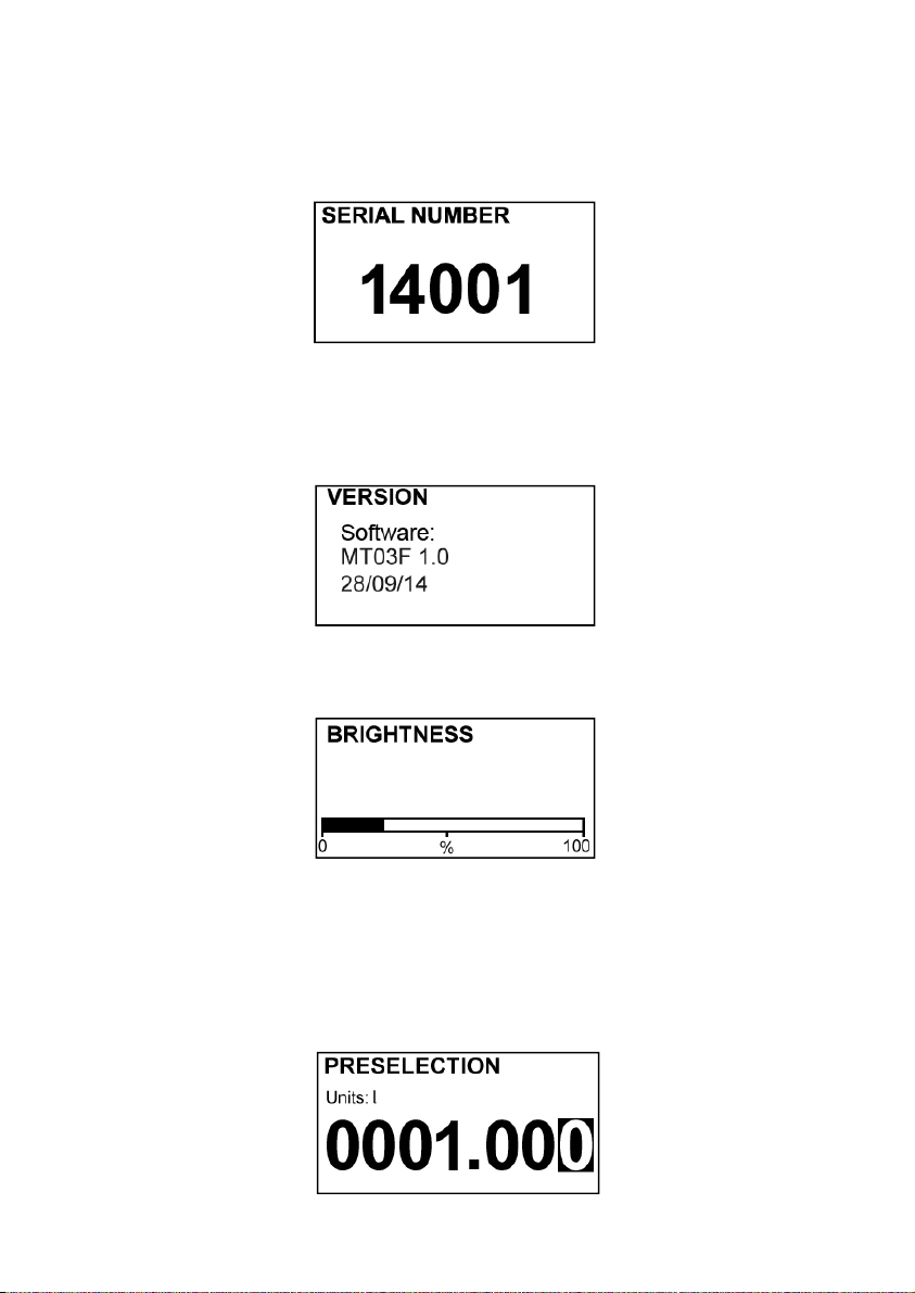
It has 8 digits and 2 decimals. Decimals are lost as more integer digits are needed.
To reset the totalizer, see the section 5 on page 14.
9 SERIAL NUMBER
In this section the converter serial number is shown.
10 SOFTWARE VERSION
From the main menu, if “Software version” is selected, the screen will show this data and
the corresponding date.
11 BRIGHTNESS
With this option the screen backlight can be adjusted.
12 BATCHING
A batching process is performed using the following parameters:
- Preset value. Is the amount to be dispensed. The MT03F can work with one or two
presets.
- Partial counter. Indicates the batching process. Its value is zero at the start of a batch
and increases when the MT03F receives signal from a flowmeter.
26
Page 27
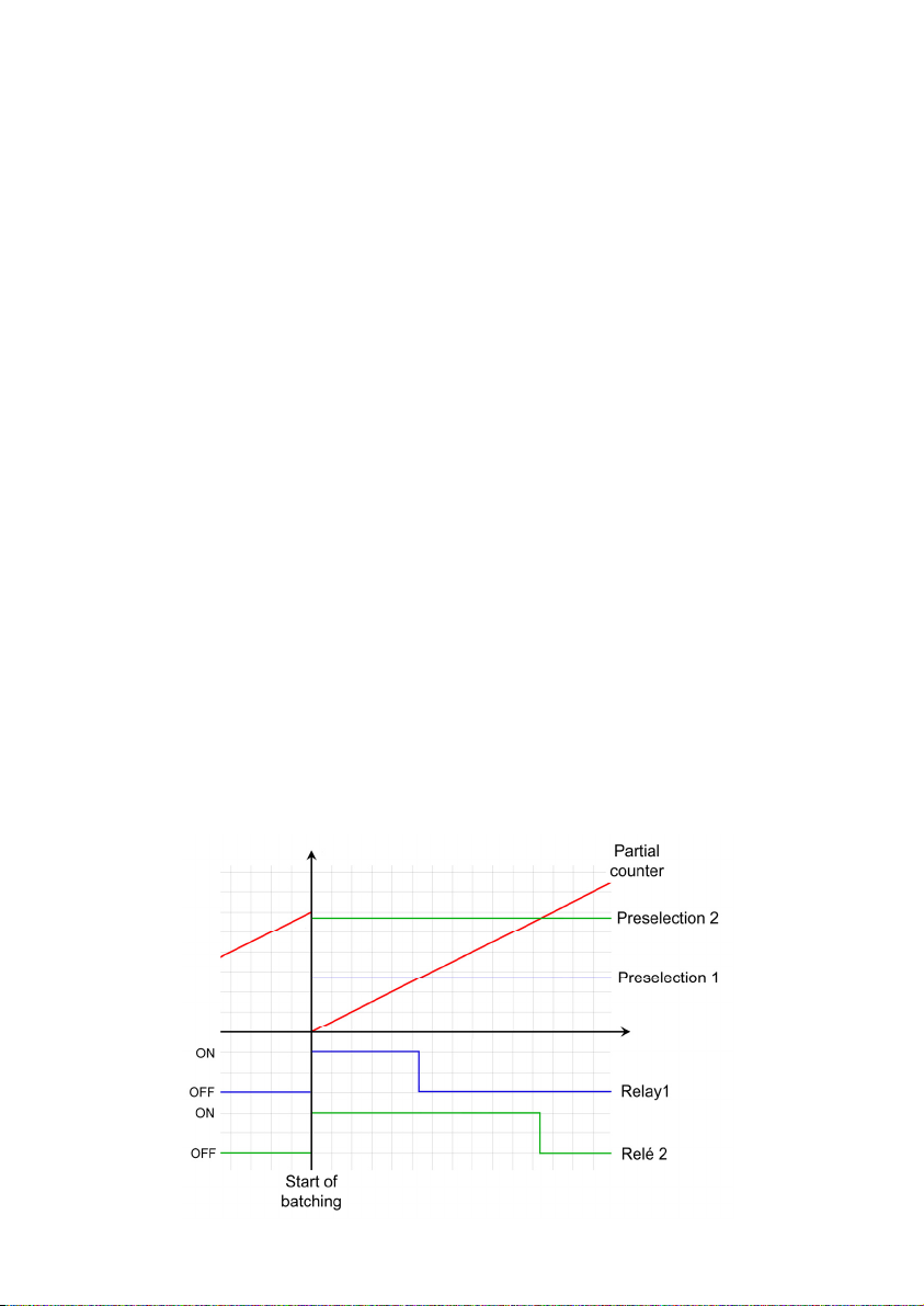
- Relays. If configured as batching they change its state when the accumulated total
reaches the preset value associated with each relay.
From the working screen, pressing the key (Down / Left) the preset input screen is shown.
On this screen, enter the amount to be dispensed. There are 3 possibilities:
- If only relay 1 is programmed as batching (see section 7.6.1 on page 23), only the
"Preset 1" appears, and the entered value is the one that when the partial counter
reaches this value will produce a change of state in relay 1.
- If only relay 2 is programmed as batching (see section 7.6.1 on page 23), only the
"Preset 2" appears, and the entered value is the one that when the partial counter
reaches this value will produce a change of state in relay 2.
- If both relays are programmed as batching (see section 7.6.1 on page 23), the
"Preset 1" screen appears first, and after the "Preset 2" . The values entered are
those that when the partial counter reaches each value will produce a change of
state in the relay 1 or relay 2.
NOTE: A zero preset value or the two presets with the same value are not allowed.
12.1 Batching start
To start a batching process, the equipment should be on a screen where the accumulated
total appears. Otherwise, the start of the manoeuver will have no effect.
The batching process can be started by shorting the remote Reset terminals (see section
3.2.7 on page 12) or by pressing the key (Escape).
From that moment, the partial counter will reset and relays programmed as batching will
change their state to ON.
12.2 Process and end of batching
The accumulated total counter increases when the MT03F receives flow rate signal.
When it reaches the value of each preset, the associated relay changes its state to OFF.
If during the batching process the key (Escape) is pressed the relays are set to OFF and the
process is finished despite not having reached the preset value. If the event that it is
necessary to complete a batch which was stopped, either by pressing the key (Escape) or
by power failure, program the preset value as the difference between the initial preset value
and the partial counter value shown when the process was stopped.
27
Page 28

13 WORKING SCREEN
V
r
r
When exiting the menu, the display shows the working screen. To scroll between the six
operating screens, press the key (Down / Left) or (Up).
14 MAINTENANCE
No special maintenance is required .
14.1 Fuse
The device has a Ø5 x 20 mm fuse as a protection at power supply input. The fuse rating
depends on the nominal supply voltage.
In the event that the fuse blows, this should be replaced with one of the same value.
15 MEASUREMENT ERROR CORRECTIONS
The obtaining of K factor of the flowmeters is performed by water at 20 oC whereby a
factor for a liquid of density 1 kg/l and viscosity of 1 mPa·s is obtained. If a liquid is used
with different characteristics from the above specified, measurement errors can be
induced.
To correct these errors the K factor can be modified in the installation menu (see page
17).
Example 1 - Shortage of volume
If we have a flowmeter which specifies K (pulses/litre) = 1.985, and when we check the
volume of a batch, we find that instead of having 100 litres as programmed, we only have
95 litres (5% less) we have to apply the following correction:
Fk = Original K factor = 1,985
V = Expected volume = 100
Vr = Obtained volume = 95
Fk n = New K factor = ? (2,089)
Fk n = Fk
V
Example 2 - Excess of volume
If we have a flowmeter body which specifies K (pulses/litre) = 1.985, and when we check
the volume of a batch, we find that instead of having 100 litres as programmed, we have
105 litres (5% more) we have to apply the following correction:
Fk = Original K factor = 1,985
V = Expected
Vr = Obtained volume = 105
Fk n = New K factor = ? (1,887)
volume = 100
V
Fk n = Fk
V
28
Page 29
16 ASSOCIATED SOFTWARE WINSMETER MT03
Most of the steps in the preceding paragraphs can be done by means of the device
associated software Winsmeter MT03, which allows working in a more comfortable and
intuitive way.
Such software can be downloaded from the “Downloads” section of the Tecfluid S.A.
www.tecfluid.com/downloads
16.1 USB cable connection and drivers installation
Extract the files from the winsmeter MT03.zip to a new system folder.
Execute the Setup.exe file and follow the steps for the installation.
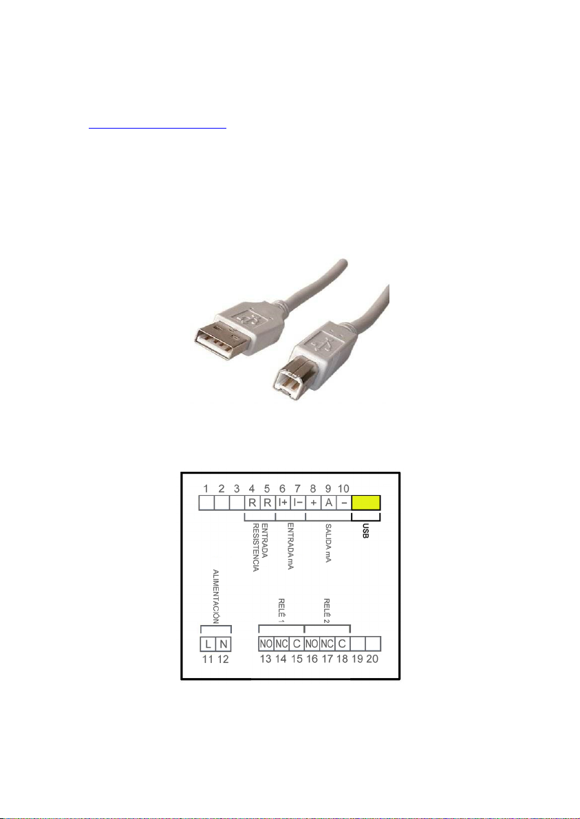
In order to connect the converter to a computer an USB cable is required. This cable is type
A at one end and type B at the other, and it is readily available on the market.
The ends of the cables can be seen in the picture.
The USB connector is located at the rear side of the converter.
Connect the USB cable at one end to the converter and at the other to the computer where
the software is installed.
Power on the electronic converter.
29
Page 30
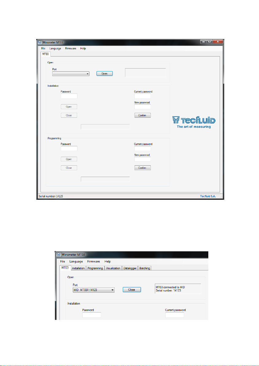
Execute the program WinsmeterMT03 following the sequence Start – Programs – Tecfluid
S.A. - WinsmeterMT03.
16.2 Port connection
In the "Port" section, choose the appropriate port for the converter. This will appear with the
name of the port followed by MT03F and its serial number. Then click "Open".
Once the port is open, the button "Open" in the "Installation" and “Programming” sections
activates.
30
Page 31
16.3 Access to installation and programming
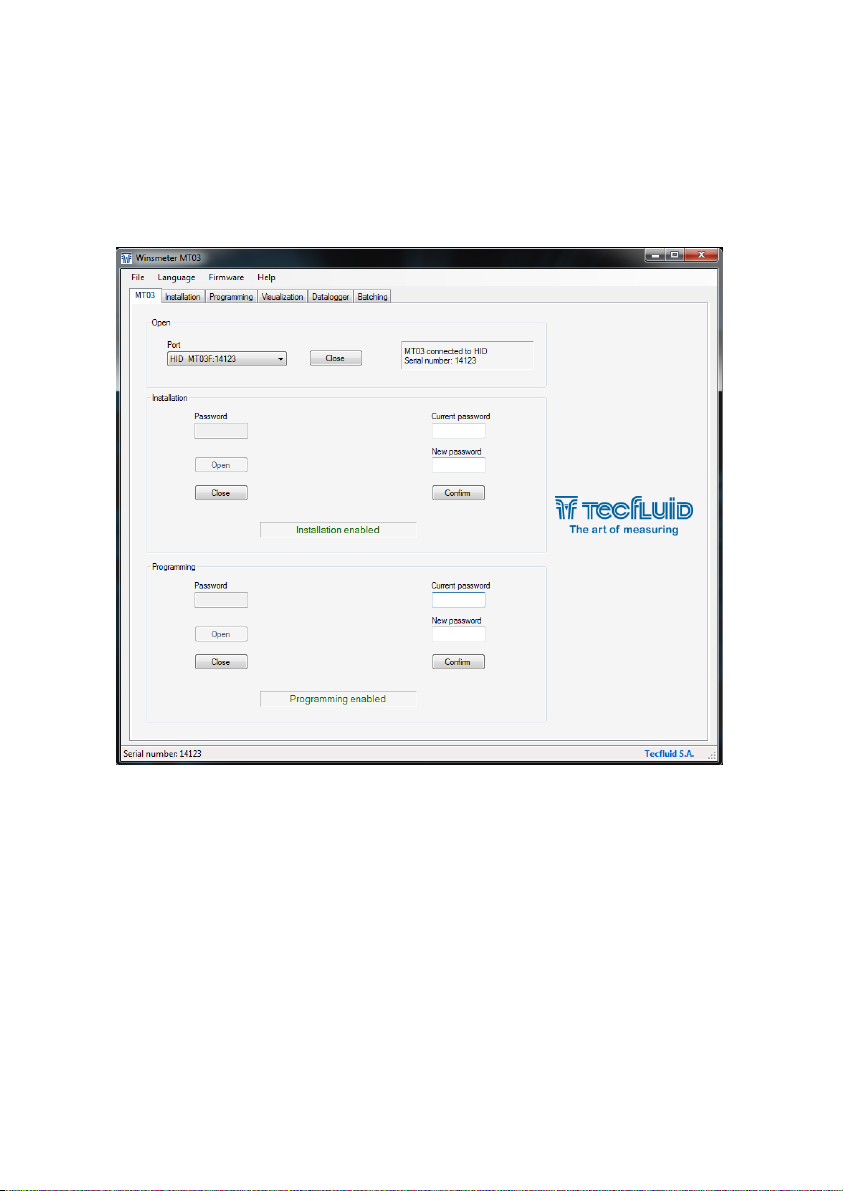
In order to change the data contained in the "Install" tab, you must enter a password.
The default password is install, and it can be changed using the boxes on the right of the
"Installation" section.
Likewise, to change the data contained in the "Programming" tab it is necessary to enter the
password which by default is program. This can be changed using the boxes on the right of
the "Programming" section.
Once the password is written, press “Enter” or "Open", and the installation or programming
tab will open. At the bottom of each section the text "Installation tab open" or "Programming
tab open" will be displayed
To enter the Installation window, just click the corresponding tab.
31
Page 32
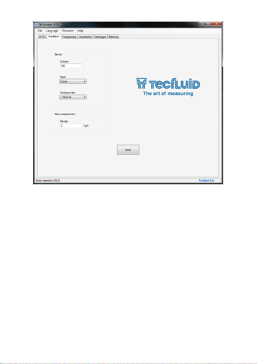
In the installation window the parameters that adapts the converter to a sensor can be
configured.
To transfer data to the MT03F converter, press the “Send” button. The message "Saving
program" will appear for two seconds in the converter screen. The installation data will be
stored in the memory of the converter.
Likewise, to enter into the programming window, just click the corresponding tab.
32
Page 33
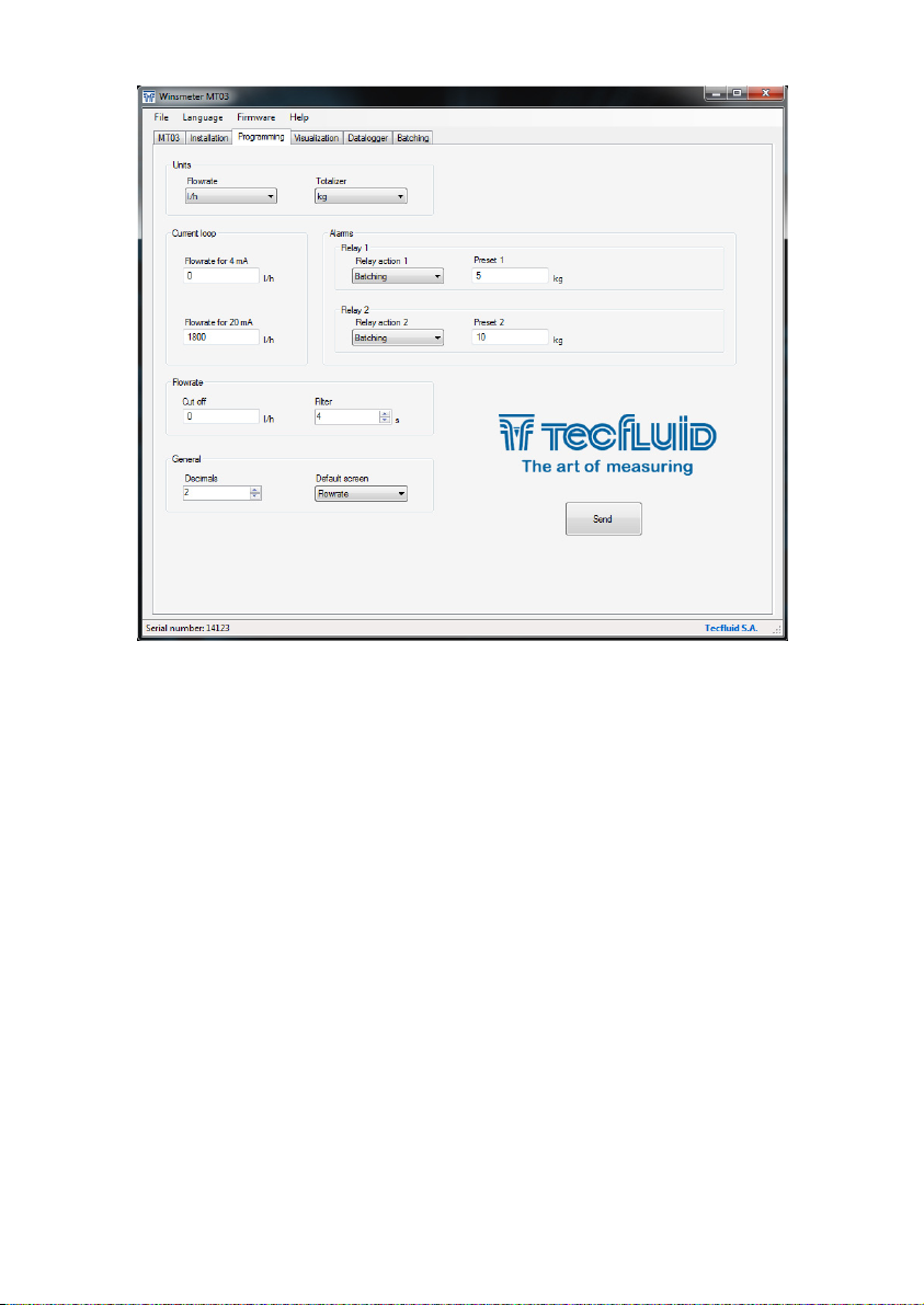
Changing the parameters of this screen you can program the different functions of the
equipment.
As in the previous paragraph, to program this data to the MT03F converter, press the “Send”
button. The message "Saving program" will appear for two seconds in the converter screen.
The programming data will be stored in the memory of the converter.
16.4 Visualization
When the communication with the computer port is established (see section 16.2), the tab
"Visualization" opens. This tab lets you view real-time flow rate, totalizer and partial counter
values, as well as the current value of the analog output and the status of the relay outputs.
It is an intuitive tool to verify that the instrument has been installed and programmed
correctly.
33
Page 34
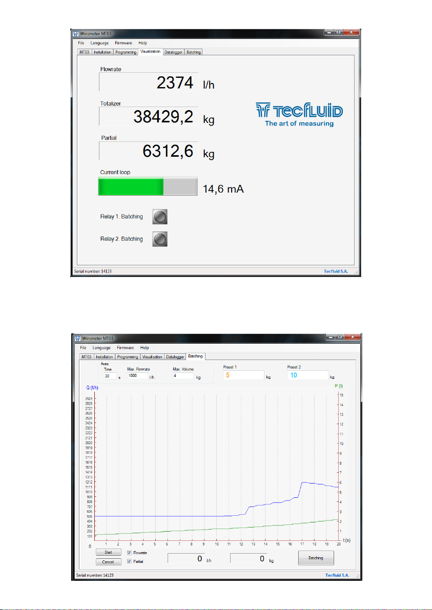
16.5 Graphic
This screen can graphically display the flow rate and partial counter progress. It is intended
to be most useful in batching processes. With "Start" and "Cancel" buttons the graphic can
be drawn and with the "Batching" button starts or cancels a batching process.
34
Page 35
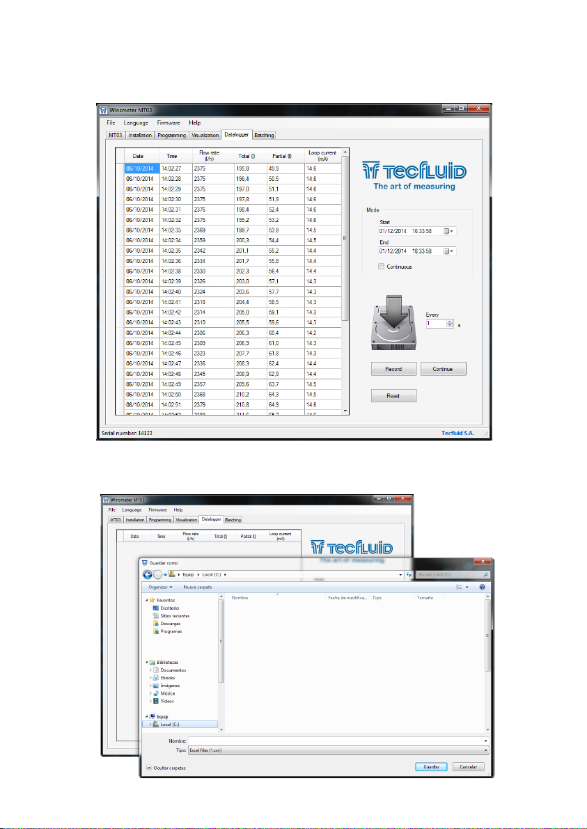
16.6 Datalogger
In this screen the different process variables of the converter can be registered in a file.
The time between samples can be set, as well as the start and end of the record.
When the "Register" button is pressed, the window that allows to give a file name and define
its location appears.
35
Page 36
The created file has CSV format, which can be viewed directly with a spreadsheet such as
Microsoft Excel.
16.7 Firmware updates
New firmware updates can be published in the website. These updates contain
improvements or bug fixes that make the equipment operates at best conditions.
The updates can be downloaded from the following link of Tecfluid S.A. website
www.tecfluid.com/download
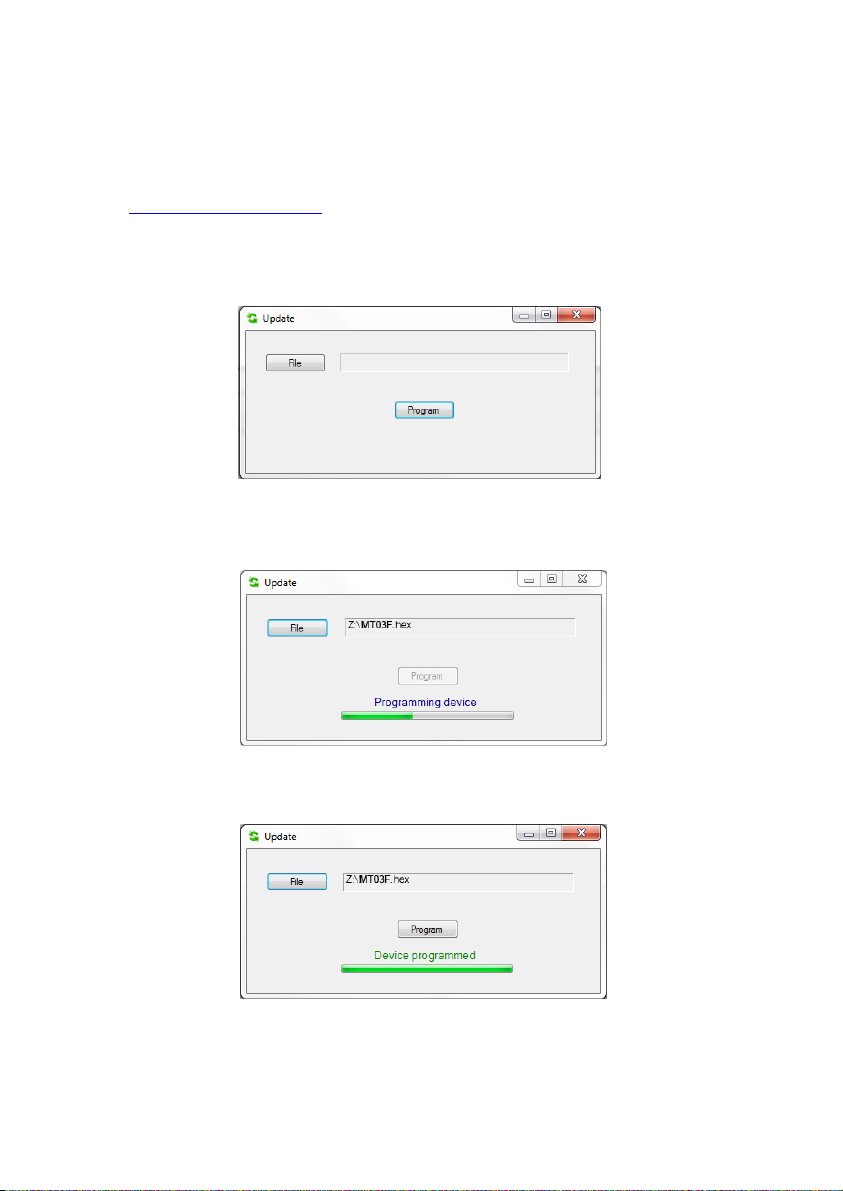
To update the equipment, go to menu “Firmware” - “Update”, and a screen with the button
“File” will appear. Pressing this button file explorer can be accessed. The downloaded file
has to be searched there.
Once the file is selected, press the “Program” button. A message “Programming device” will
appear.
The process takes about 90 seconds, after which the message “Device programmed” will
appear.
From this moment, the converter MT03F already has the new version of Firmware.
36
Page 37

17 TECHNICAL CHARACTERISTICS
Power supply
90 ... 265 VAC 50, 60 Hz
18 ... 36 VDC
Power consumption: 5 VA
Pulse input
From 0 to VCC, where VCC= 5V ... 24V
NPN open collector
Potential free contact
Pickup input
Peak to peak voltage: 30 mVpp ... 10 Vpp
Analog output
4-20 mA. Active or passive. galvanically isolated from the power supply.
Pulse output
Optoisolated. NPN bipolar transistor. Vmax: 30 VDC. Imax: 30 mA.
Pulse input repeater
Minimum frequency: 1 / 60 Hz
Maximum frequency: 5000 Hz
Relay outputs
2 relay with potential free contacts.
Contact characteristics:
Maximum voltage : 220 VDC, 250 VAC
Maximum current: : 3 A
Totalizer
Nº of digits: 8 (2 decimals)**
Digit size: 11 mm
Reset: by means of keyboard
Accumulated total
Nº of digits: 8 (2 decimals)**
Digit size:: 11 mm
Flow rate indication
Nº of digits: 5 (up to 2 decimals configurable)**
Digit size: 11 mm
** When the available digits are full and the integers overflow a decimal is automatically
lost.
Ambient temperature range:
-20 ... +60 ºC
37
Page 38
Housing
Material:
(1)
Box: Noryl SE1, GFN2, 701 black
Front frame: Lexan 920 black
(1)
Ingress protection:
Back side: IP30
Front side: IP50
Silicone sleeves for the front side are available. They provide an IP65 ingress protection.
Conforms to Low voltage Directive 2006/95/CE
Conforms to Electromagnetic compatibility Directive 2004/108/CE
Conforms to Waste Electrical and Electronic Equipment Directive 2002/96/CE
(1)
Noryl and Lexan are trademarks of Saudi Basic Industries Corporation (SABIC).
18 DIMENSIONS
Hole panel
38
Page 39

19 TROUBLESHOOTING
Problem Probable cause Solution
Check that the input type
programmed in the menu matches
the connection made (see page
18)
Check that the frequency of the
input signal is lower than that
indicated in the programmed filter
(see page 18)
The flow rate is 0, the
accumulated total
counter and the totalizer
do not increase their
value
Incorrect input
Filter too restrictive
Cable disconnected
The flow rate displayed
is 0
The display is blank Blown fuse Change the fuse
The analog output gives
always 4 mA or 20 mA
The analog output gives
always 0 mA
The flow rate is smaller than
programmed as cut off
Current output range not properly
programmed
Cable disconnected Check the cable connection
Connect the cable between the
pulse transmitter and the MT03F
Decrease the value of the cut off
(see page 22)
Program the range properly (see
page 24)
39
Page 40

WARRANTY
Tecfluid S.A. guarantees all the products for a period of 24 months from their sale, against all faulty
materials, manufacturing or performance. This warranty does not cover failures which might be
imputed to misuse, use in an application different to that specified in the order, the result of service
or modification carried out by personnel not authorized by Tecfluid S.A., wrong handling or
accident.
This warranty is limited to cover the replacement or repair of the defective parts which have not
damaged due to misuse, being excluded all responsibility due to any other damage or the effects
of wear caused by the normal use of the devices.
Any consignment of devices for repair must observe a procedure which can be consulted in the
website www.tecfluid.com, “After-Sales” section.
All materials sent to our factory must be correctly packaged, clean and completely exempt of any
liquid, grease or toxic substances.
The devices sent for repair must enclose the corresponding form, which can be filled in via website
from the same “After-Sales” section.
Warranty for repaired or replaced components applies 6 months from repair or replacement date.
Anyway, the warranty period will last at least until the initial supply warranty period is over.
TRANSPORTATION
All consignments from the Buyer to the Seller´s installations for their credit, repair or replacement
must always be done at freight cost paid unless previous agreement.
The Seller will not accept any responsibility for possible damages caused on the devices during
transportation.
TecfluidS.A.
NarcísMonturiol33
08960SantJustDesvern
Barcelona
Tel:+34933724511
QualityManagementSystemISO9001cerfiedby
PressureEquipmentDirecve97/23/CEcerfiedby
ATEXEuropeanDirecve94/9/CE
cerfiedby
Fax:+34934734449
tecfluid@tecfluid.com
HART®isaregisteredtrademarkofHARTCommunicaonFoundaon
www.tecfluid.com
Thetechnicaldatadescribedinthismanualissubjecttomodificaonwithoutnoficaonifthetechnicalinnovaonsin
themanufacturingprocessessorequire.
40
 Loading...