

Tecfluid LT14 / PVC-C, LT106, LTL106, LT14 / PVC, LTL14 / PVC-C Instruction Manual
...
R-MI-LT Rev.: 3 english version
Instructions manual
The art of measuring
Series LT
Level gauge

2
Thank you for choosing a product from Tecfluid S.A.
This instruction manual allows the installation, configuration,
programming and maintenance. It is recommended to read it before
using the equipment.
This document shall not be copied or disclosed in whole or in any
part by any means, without the written permission of Tecfluid S.A.
Tecfluid S.A. reserve the right to make changes as deemed
necessary at any time and without notice, in order to improve the
quality and safety, with no obligation to update this manual.
Make sure this manual goes to the end user.
Keep this manual in a place where you can find it when you need
it.
In case of loss, ask for a new manual or download it directly from
our website www.tecfluid.com Downloads section.
Any deviation from the procedures described in this instruction
manual, may cause user safety risks, damage of the unit or cause
errors in the equipment performance.
Do not modify the equipment without permission. Tecfluid S.A. are
not responsible for any problems caused by a change not
allowed. If you need to modify the equipment for any reason,
please contact us in advance.
PREFACE
WARNINGS

3
TABLE OF CONTENTS
SERIES LT
1 INTRODUCTION .......................................................................... 6
2 WORKING PRINCIPLE .................................................................. 6
3 MODELS ...................................................................................... 6
4 RECEPTION ................................................................................. 7
5 HANDLING ................................................................................... 7
6 INSTALLATION ............................................................................. 7
6.1 Minimum distances ............................................................. 8
7 LEVEL ASSEMBLY IN TWO SECTIONS .......................................... 10
7.1 Model LT106 (stainless steel) .............................................. 10
7.2 Model LT14 (plastic) ........................................................... 14
8 LEVEL READING ........................................................................... 18
9 FLOAT TYPES .............................................................................. 18
10 AMD LIMIT SWITCH ....................................................................... 19
10.1 Introduction ........................................................................ 19
10.2 Operation ........................................................................... 19
10.3 Switching point adjustment ................................................. 19
10.3.1 LT models ............................................................. 19
10.3.2 LTL models ........................................................... 20
10.4 Electrical connection ........................................................... 20
10.5 Mounting ........................................................................... 21
11 AMM LIMIT SWITCH ..................................................................... 21
11.1 Introduction ........................................................................ 21
11.2 Operation ........................................................................... 21
11.3 Switching point adjustment ................................................. 21
11.3.1 LT models ............................................................. 21
11.3.2 LTL models ........................................................... 22
11.4 Electrical connection ........................................................... 23
11.5 Mounting ........................................................................... 23
12 APR LIMIT SWITCH ...................................................................... 24
12.1 Introduction ........................................................................ 24
12.2 Operation ........................................................................... 24
12.3 Switching point adjustment ................................................. 24

4
12.3.1 LT models ............................................................. 24
12.3.2 LTL models ........................................................... 25
12.4 Electrical connection ..................................................................... 25
13 AAR LIMIT SWITCH ...................................................................... 27
13.1 Introduction ........................................................................ 27
13.2 Operation ........................................................................... 27
13.3 Switching point adjustment ................................................. 27
13.4 Electrical connection ........................................................... 28
14 LTE TRANSMITTER ...................................................................... 29
14.1 Introduction ........................................................................ 29
14.2 Operation ........................................................................... 29
14.3 Models ............................................................................... 29
14.4 Remote transmitter .............................................................. 30
14.4.1 Electrical connection .............................................. 30
14.4.2 Mounting ............................................................... 30
14.5 Compact transmitter ........................................................... 31
15 LTDR TRANSMITTER ................................................................... 32
16 MAINTENANCE ............................................................................ 32
16.1 Series LT ........................................................................... 32
16.2 AMD limit switch maintenance ............................................. 32
16.2.1 Electrical verification ................................................ 32
16.3 AMM limit switch maintenance ............................................ 33
16.4 APR limit switch maintenance .............................................. 33
16.5 AAR limit switch maintenance .............................................. 33
17 TECHNICAL CHARACTERISTICS ................................................... 34
17.1 Series LT ........................................................................... 34
17.2 AMD limit switch ................................................................. 34
17.3 AMM limit switch ................................................................ 35
17.4 APR limit switch ................................................................. 35
17.5 AAR limit switch ................................................................. 35
17.6 LTE transmitter .................................................................... 35

5
18 SAFETY INSTRUCTIONS ............................................................... 36
18.1 Pressure equipment directive ............................................. 36
18.2 Certificate of conformity TR CU (EAC marking) ..................... 36
19 ADDITIONAL INSTRUCTIONS FOR THE ATEX VERSION ................. 37
19.1 Flameproof enclosure ......................................................... 37
19.1.1 Surface temperature .............................................. 37
19.1.2 Connecting conductive parts to earth ....................... 37
19.1.3 Maintenance .......................................................... 38
19.1.4 Technical characteristics of the ATEX version .......... 38
19.1.5 Marking ................................................................. 38
20 NAME PLATE ................................................................................ 39
21 DIMENSIONS ................................................................................ 40
22 ATEX CERTIFICATE ....................................................................... 44
23 ATEX DECLARATION OF CONFORMITY ........................................ 46
6
1 INTRODUCTION
The level gauges series LT are very robust equipment and resistant to extreme conditions of
temperature and pressure, as well as corrosive chemicals, depending on the manufacturing
materials used.
They can fit switches that allow to detect a specific level and provide an alarm signal to a
remote device. They can also fit a resistive sensor with a 4-20 mA transmitter proportional to
the level.
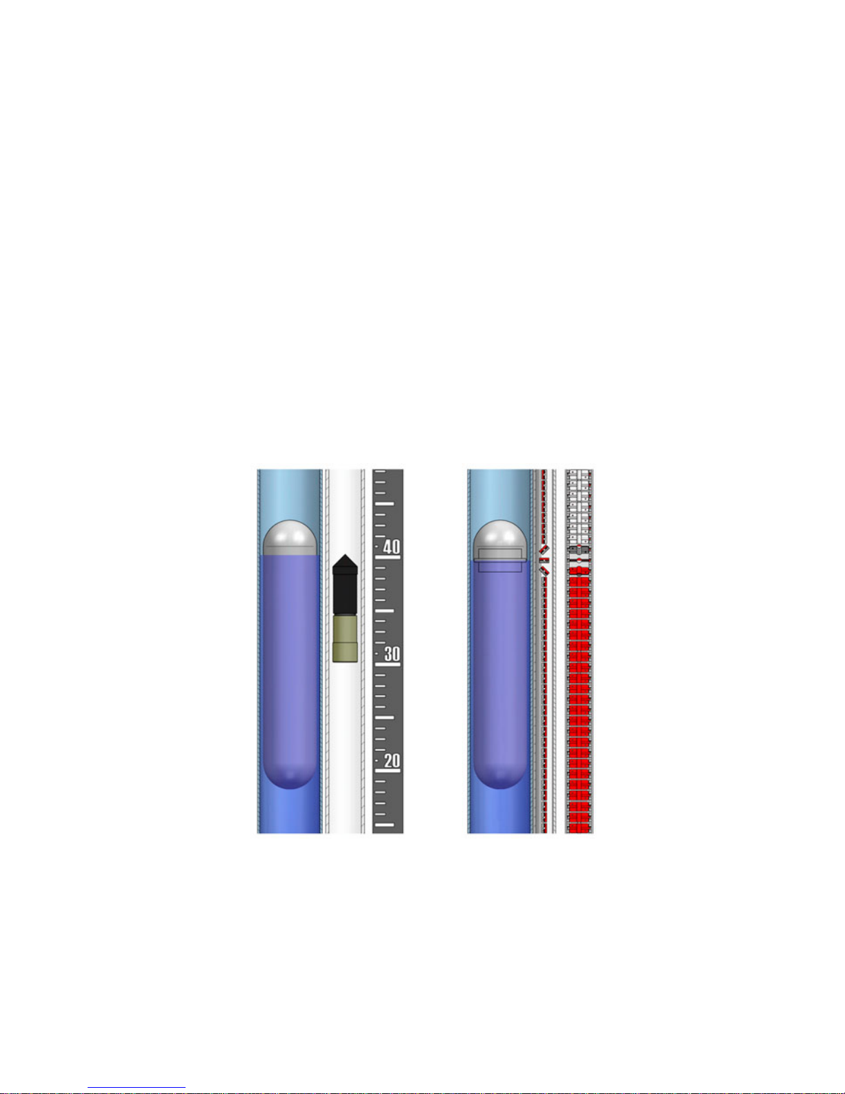
2 WORKING PRINCIPLE
A float inside a chamber communicated with the tank whose liquid level needs to be
measured, floats on the liquid surface and moves together with it, as level increases or
decreases.
The float is designed for the specific working liquid density and shows the tank level by
means of magnetic coupling.
This is possible thanks to an external float housed in a borosilicate glass pipe (LT models)
that rises or falls depending on the height of the level in the tank, or by a magnetic strips rail
(LTL models), that mounted externally and isolated of the level gauge chamber, changes its
colour with the magnetic field.
3 MODELS
LT ... LTL106 Body in AISI 316L, flanged connection
LT ... LTL116 Body in AISI 316L, threaded connection
LT ... LTL14 Body in PVC, PVC-C, PP or PVDF, flanged connection
LT ... LTL15 Body in SS 316L with internal PTFE coating, flanged connection
7
The working temperatures are given for an ambient temperature of 20ºC.
The couplings to the tank must be aligned and perpendicular.
Flange bolts should be tightened progressively in a criss-cross sequence to avoid causing
stress.
With threaded connections, they should be tightened progressively and together.
For the LT models (with a glass tube), it is recommended to remove this tube before
mounting the level to the tank.
4 RECEPTION
The series LT level gauges are supplied conveniently packaged for their protection during
transportation and storage, together with their instructions manual for installation and
operation.
All the instruments have been verified in our facilities, ready for installation and operation.
LT level gauges are supplied with the float blocked in its bottom position by means of a stop
introduced into the lower side coupling.
Before mounting on the tank, this stop must be removed.
5 HANDLING
It must be done carefully and without blows.
6 INSTALLATION
Important: Check that the maximum working pressure is below the limit shown on the
identification label of the equipment. Check that the maximum working temperature of the
liquid is within the limits given in the following chart.
Materials Liquid temperature range
EN 1.4404 (AISI 316L) -20ºC … 400ºC
EN 1.4404 (AISI 316L) -20ºC … 200ºC
PP -10ºC … 80ºC
PVDF -20ºC … 145ºC
PTFE -20ºC … 150ºC
Model
LT106
LTL106
LT … LTL14 / PP
LT … LTL14 / PVDF
LT … LTL15 / PTFE
LT … LTL14 / PVC-C PVC-C 0ºC … 70ºC
LT … LTL14 / PVC PVC 0ºC … 45ºC
8
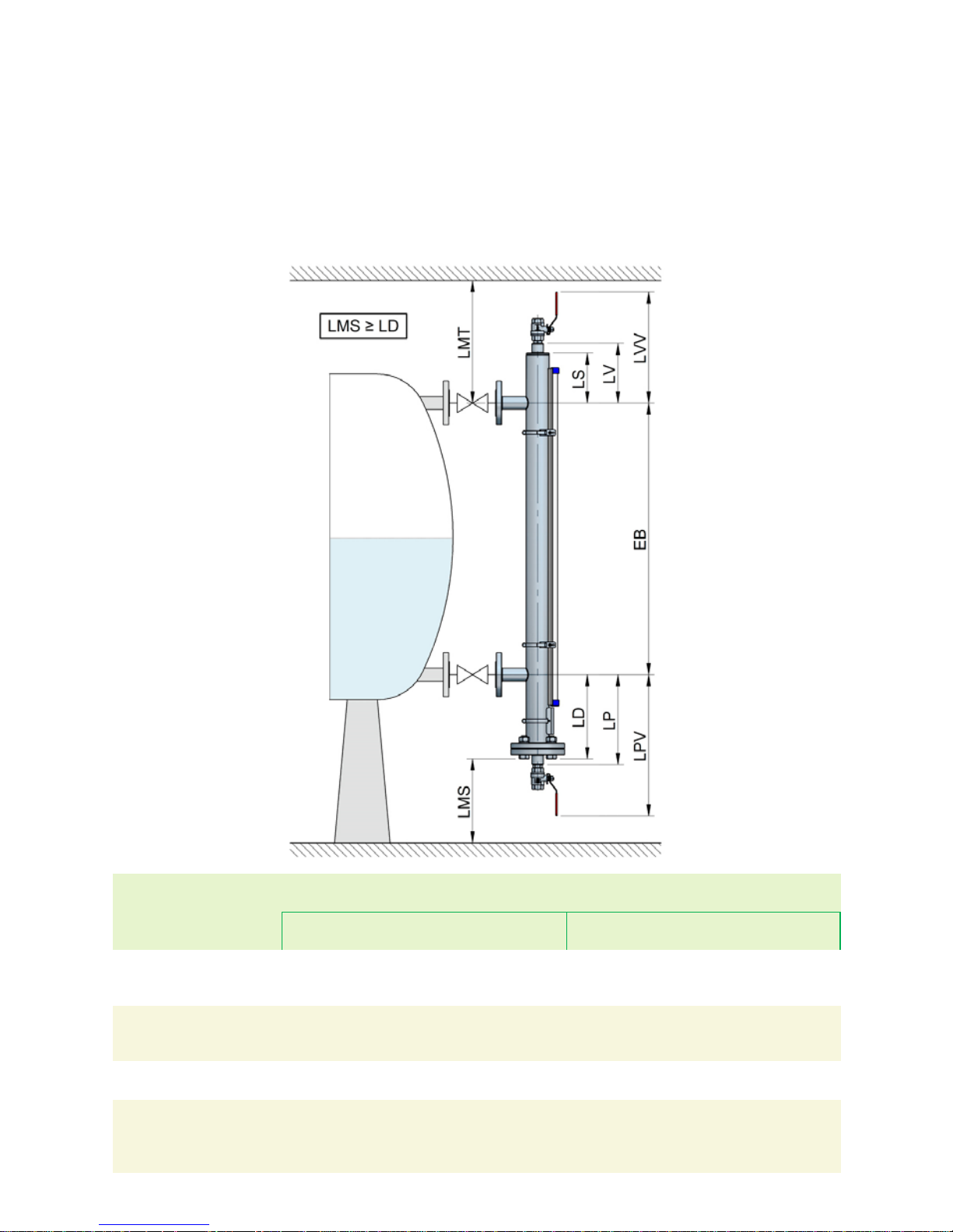
6.1 Minimum distances
It is important to take in account some distances that must be kept in order to remove the
float due to a change in density or for maintenance purposes.
Distance LMS between the lowest side of the level gauge and the floor must be kept longer
or equal to LD distance.
On the other hand, the lower dimension LD, LP or LPV of series LT level gauges is variable
depending on the working liquid density. The lower the density, the longer the dimension.
Model
Liquid
density (kg/l)
Lower dimension
Without
drain (LD)
With drain
(LP)
With drain +
valves (LPV)
Without
vent (LS)
With vent
(LV)
With vent +
valve (LVV)
LT … LTL /
AISI 316L
0,55 ... 0,59
0,60 ... 0,91
≥ 0,92
430
340
260
445
355
275
590
500
420
130 155 300
LT … LTL /
PVC
0,60 ... 0,79
0,80 ... 0,89
≥ 0,90
400
310
240
525
435
365
150 140 265
LT ... LTL /
PP
≥ 0,70 240 365 150 165 290
LT … LTL /
PVDF
0,80 ... 0,89
0,90 ...0,99
1,00 … 1,19
≥ 1,20
415
340
290
240
540
465
415
365
150 165 290
Upper dimension
9
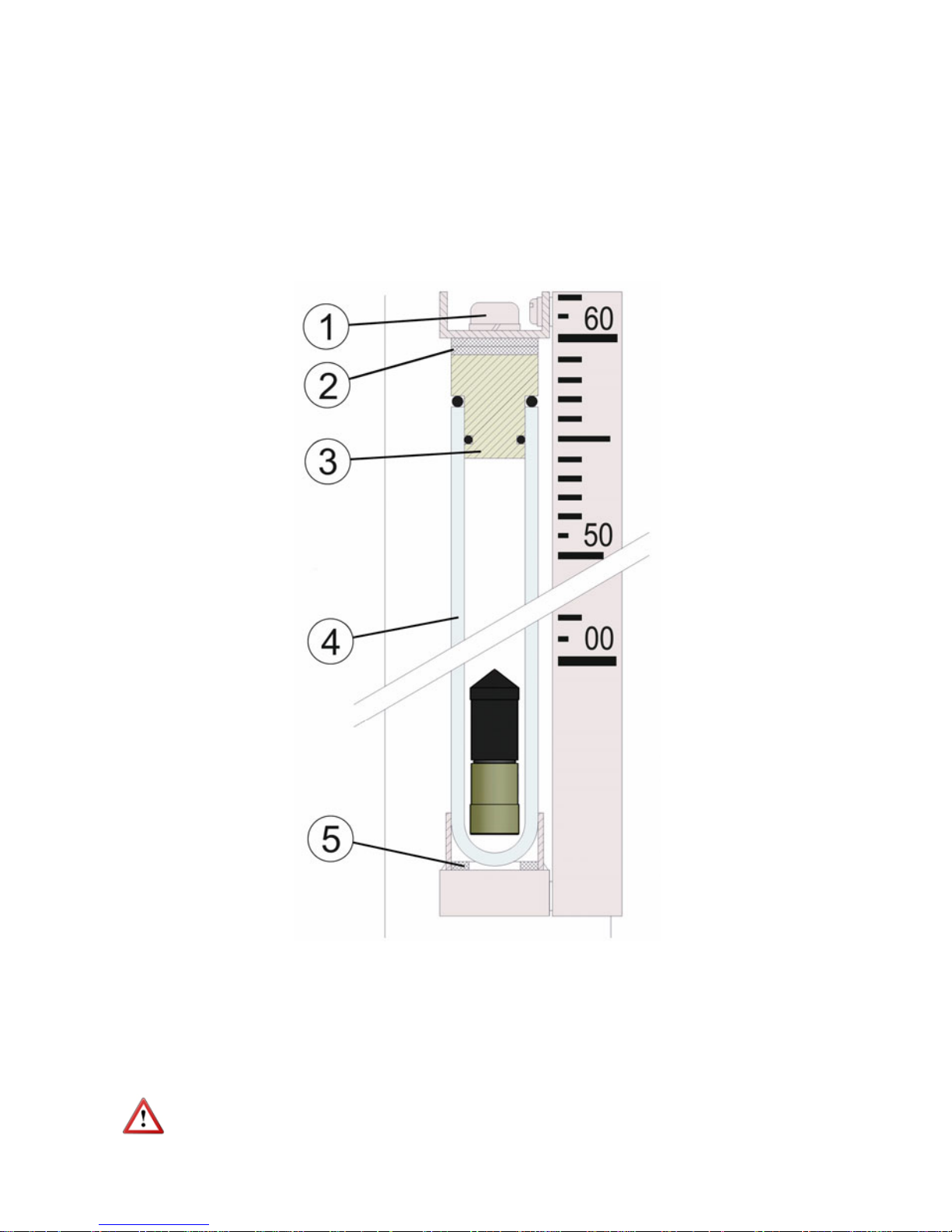
For the LT level gauges, once the level is connected to the tank, fill the glass tube, and next
reassemble the glass tube on the chamber.
This process should be done in the following way:
Remove the M8 upper allen screw (1).
Withdraw the glass tube from its support and remove the plug at the top (3).
Fill the glass tube (4) with the liquid supplied with the level gauge.
Insert the plug (3) in the tube and maintain in a vertical position.
To place the tube on the body, proceed as follows:
Check that the rubber seal (5) is in its position.
The bottom of the glass tube (4) should rest on the rubber seat (5).
Mount the spacer (2) in its position.
Assemble the glass tube in its position and screw the allen screw (1) into the plug (3).
The M8 DIN 912 allen screw (1) should not be tightened too hard, it is enough to tighten until
a slight resistance is felt.
10
7 LEVEL ASSEMBLY IN TWO SECTIONS
When the level gauge is delivered in two sections, due to its total length, the following
instructions must be followed carefully for its correct installation.
The numbering of the different elements corresponds to the different figures.
NOTE: Handle the glass tube sections with care.
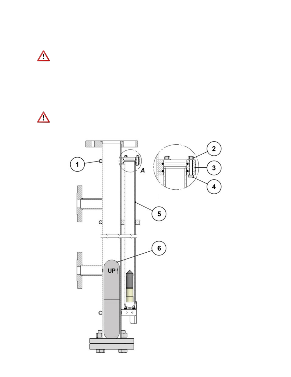
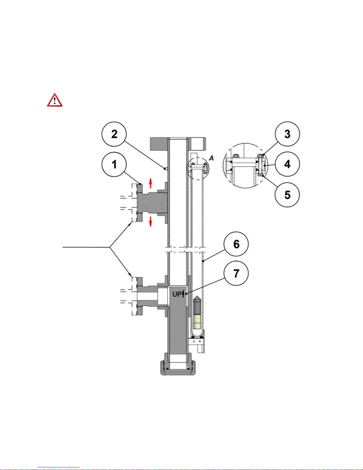
7.1 Model LT106 (stainless steel)
Fix the lower half of the level to the installation.
Remove the adhesive tape from the lower glass tube (5) and loosen the 3 screws DIN933
M5 x 30 (4) without removing the nuts (2).
In case there is not enough space to introduce the float (6) through the lower part of the
gauge body once the assembly is completed, the float must be in its correct position inside
this lower half at the time of installation.
NOTE: The clamp (1) that fixes the guide-support (3) should never be loosened.
DETAIL A
11
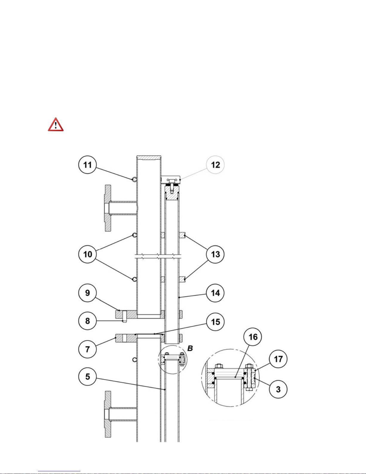
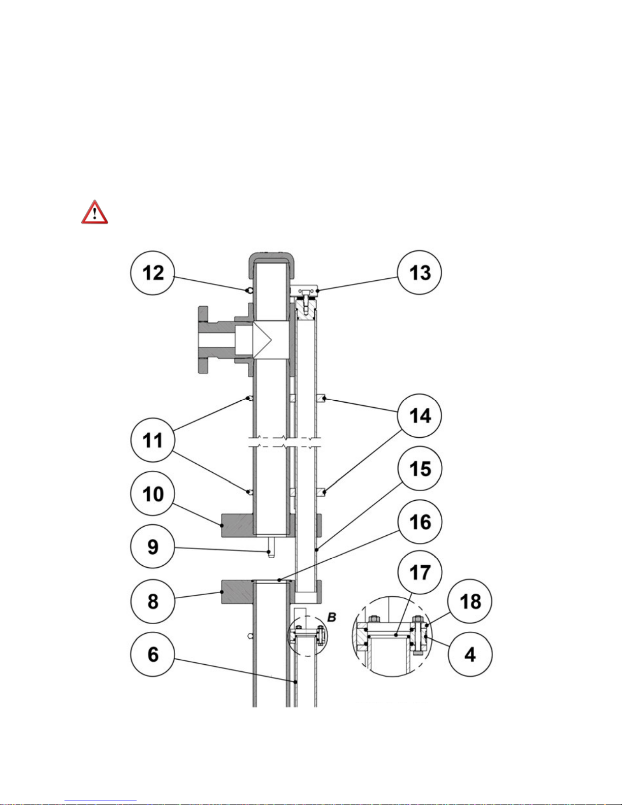
Check the placement of the NBR gasket Ø63 x 3 (15) in its seat on top of the lower flange
(7) and the NBR gasket Ø31.42 x 2.62 (16) on top of the lower glass tube (5).
Place the upper half of the level gauge above the lower half and in the coaxial position, and
carefully go down by passing the upper glass tube (14) through the corresponding hole in
the lower flange (7) until the upper flange (9) rests on the NBR gasket Ø63 x 3 (15).
Pay special attention in this phase of the assembly, since at the same time the two
guide pins (8) are inserted in the guide-holes of the lower connecting flange (7) at the same
time as the upper glass tube (14) passes through the guide-supports of the join group (17,
3).
During this step, do not remove the adhesive tape from the upper glass tube (14) or loosen
the clamp (11) that fixes the upper support (12).
NOTE: The clamps (10) that fix the guide-supports (13) should never be loosened.
DETAIL B
12
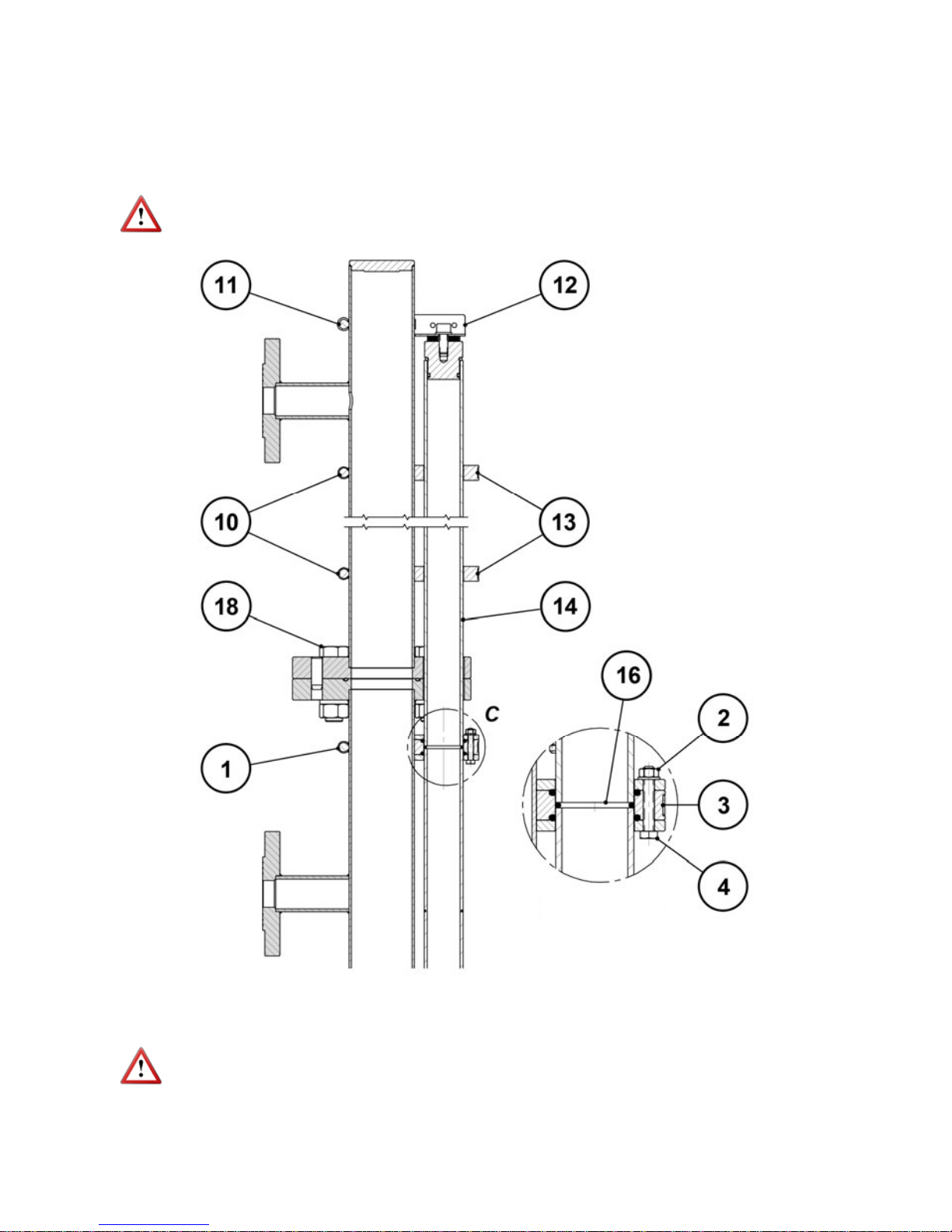
Join the two halves of the level by means of the 4 screws DIN933, variable metric according
to model (18), and their corresponding washers and nuts, and fix the level to the upper
connection of the installation.
Slightly loosen the clamp (11) that fixes the upper support (12), remove the adhesive tape
from the upper glass tube (14) and lower it until it rests on the seal (16). Gently press the
tube longitudinally against the seal and tighten the 3 screws (4) and their nuts (2).
NOTE: The clamps (1, 10) that fix the guide-supports (3,13) should never be loosened.
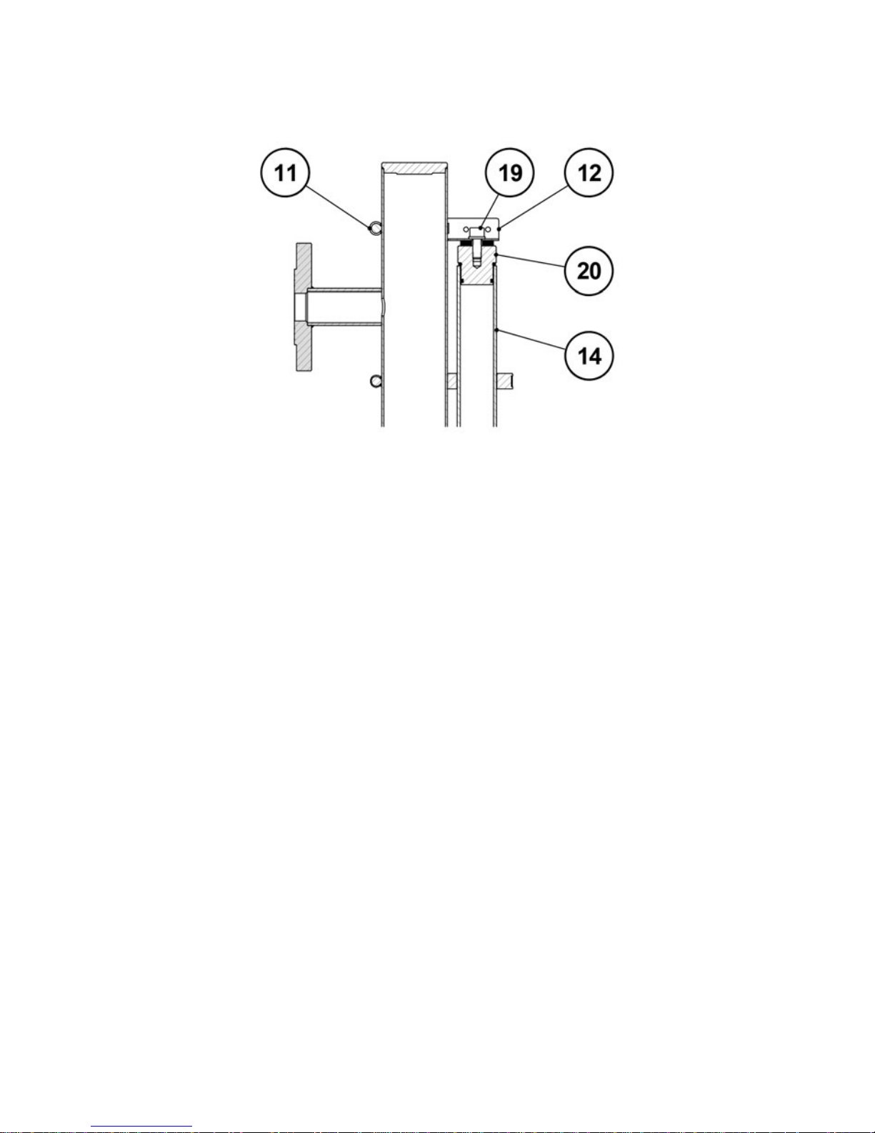
IMPORTANT NOTE: The joint group of the 2 sections of glass tube does not fix its
longitudinal displacement, but ensures the correct sealing of the joint.
DETAIL C
13
Remove the screw (19) and the plug (20) and proceed to fill the glass tube (14+5). Re-insert
the plug (20) into the tube (14) and, keeping the upper support (12) slightly pressed down,
tighten the clamp (11) and the screw (19).
14
7.2 Model LT14 (plastic)
Fix the lower half of the level gauge to the installation. The mobile flange-group (1) allows
adjusting its anchoring height.
Remove the adhesive tape from the lower glass tube (6) and loosen the 3 screws DIN933
M5 x 30 (5) without removing the nuts (3).
In case there is not enough space to introduce the float (7) through the lower part of the
gauge body once the assembly has been completed, the float must be in its correct position
inside this lower half at the time of installation.
NOTE: The clamp (2) that fixes the guide-support (4) should never be loosened.
DETAIL A
Installation
connections
15
Check the placement of the NBR gasket Ø63 x 3 (16) in its seat on top of the lower flange
(8), and the NBR gasket Ø31.42 x 2.62 (17) on top of the lower glass tube (6).
Place the upper half of the level gauge above the lower half and in the coaxial position, and
carefully go down by passing the upper glass tube (15) through the corresponding hole in
the lower flange (8) until the upper flange (10) rests on the NBR Ø63 x 3 gasket (16).
Pay special attention in this phase of the assembly, since at the same time the two
guide pins (9) are inserted in the guide-holes of the lower connection flange (8) at the same
time as the upper glass tube (15) passes through the guide-supports of the join group (18,
4).
During this step, do not remove the adhesive tape from the upper glass tube (15) or loosen
the clamp (12) that fixes the upper support (13).
NOTE: The clamps (11) that fix the guide-supports (14) should never be loosened.
DETAIL B
 Loading...