


TEAC MCDX-20, CDX-8 Service manual
MICRO Hi-Fi SYSTEM
PC board shown are viewed from parts side.
The parts with no reference number or no parts number
in the exploded views are not supplied.
As regards the resistors and capacitors, refer to the
circuit diagrams contained in this manual.
!
Parts marked with this sign are safety critical
components. they must be replaced with identical
components - refer to the appropriate parts list and
ensure exact replacement.
Parts of [ ] mark can be used only with the version designated.
[T/C]: USA/CANADA - CD-X8/MC-DX20B
[EX/M]: S. AMERICA - MC-DX20S
1 SAFETY INFORMATION
2 SPECIFICATIONS
3 ADJUSTMENT AND CHECKS
4 EXPLODED VIEW AND PARTS LIST
5 PC BOARDS AND PARTS LISTS
6 WIRING DIAGRAM
7 INCLUDED ACCESSORIES
..............................
2
3
4
6
11
19
21
CD-X8/MC-DX20
1 SAFETY INFORMATION
SAFETY INFORMATION
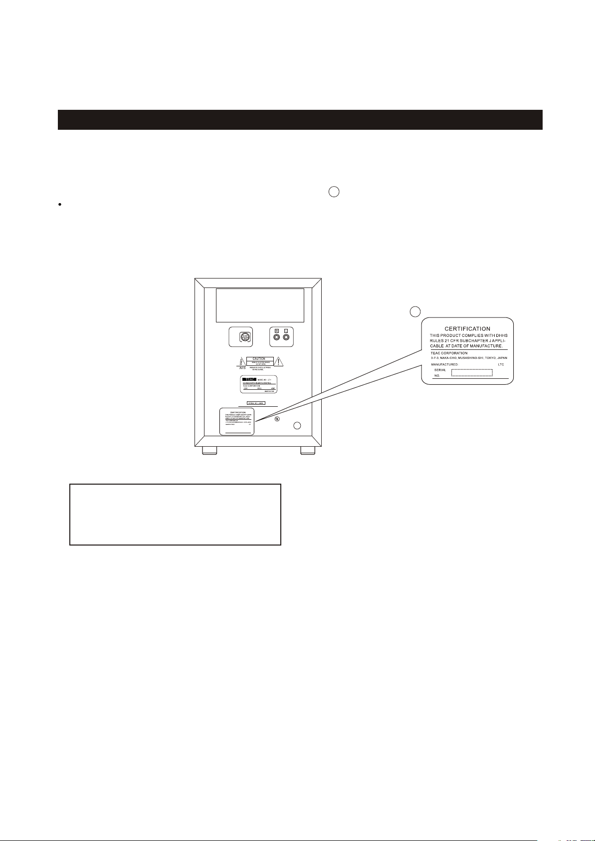
This product has been designed and manufactured according to FDA regulations " title 21, CFR, chapter 1,subchapter J,based on
The Radiation Control for Health and Safety Act of 1968" and is classified as class 1 laser product. There is not hazardous
invisible laser radiation during operation because invisible laser radiation emitted inside of this product is completely confined
in the protective housings. The label required in this regulation is shown .
CAUTION
USE OF CONTROLS OR ADJUSTMENT OR PERFORMANCE OF PROCEDURES OTHER THAN THOSE SPECIFIED HEREIN MAY
HAZARDOUS RADIATION EXPOSURE.RESULT IN
DO NOT REMOVE THE PROTECTIVE HOUSING USING SCREWDRIVER.
IF THIS PRODUCT DEVELOPS TROUBLE, MAKE A CONTACT WITH OUR SERICEMAN, AND DO NOT USE THE PRODUCT A TROUBLED
STATE.
1
FOR U.S.A.
1
Optical pickup:
Type : CMS-M95BG6
Manufacturer : Samsung Electro-Mechanic
Laser output : Less than 0.5 mW on the objective lens
Wavelength : 760 -800 nm
XXXX
R
LISTED
AUDIO PRODUCT
2

Amplifier Section
Output Power (L+R)
Output Power Subwoofer:
Input Sensitivity
Frequency Response :
Tuner Section (FM)
Frequency Range
Sensitivity (S/N30dB)
Tuner Section (AM)
Frequency Range
Sensitivity (S/N20dB)
CD Player Section
Frequency Responce
Signa-to-Noise Ratio
Wow and Flutter
CD-X8/MC-DX20
2 SPECIFICATIONS
5W + 5W
15 W
300mV
50 to 20,000 Hz
87.5 MHz to 108.0 MHz
20dBuV/m
520 to 1710 kHz
54dBuV/m
20 to 20,000 Hz (+/-1dB)
55 dB
Unmeasurable
SPEAKER SYSTEM Section
L & R speaker :
Type :
Impedance :
Subwoofer:
Impedance :
Full range flat type
4 ohms
8 ohms
GENERAL
Power Requirements:
Power Consumption:
Dimension (W x H x D ):
Weight: (net)
Standard Accessories:
120V AC, 60Hz - (USA/Canada model)
120/230V, AC,50-60 Hz (General export model)
80 W
Main Unit 160 x 226 x 86 mm
L & R Speaker 140 x 226 x 61mm
Subwoofer 160 x 234 x 330mm
Main Unit 0.96 kg
L & R Speaker 0.6 kg(each)
Subwoofer 5.3 kg
Remote Control Unit (RC-962) x 1
Subwoofer Cable x 1
Speaker Cable x 2
FM Antenna x 1
AM Antenna x 1
Battery for Remote Control x 1
Wall Mount Adaptor x 3
Wall Mount screw x 10
Tape Plastic Wall Anchor x 10
Template for Wall Mounting x 1
Owner s Manual x 1
Warranty Card x 1
Design and specifications are subject to change without notice.
Illustrations may differ slightly from production models.
Weight and dimensions are approximate.
33

CD-X8/MC-DX20
3 ADJUSTMENTS AND CHECKS
3-1 TUNER SECTION
Use a screwdriver with a plastic or ceramic grip for all adjustment.
3-1-1 FM adjustment
1. Set the function switch to the FM position.
2. Connect the signal generator output through a 75 ohm dummy
antenna to "ANT" on MAIN PCB.
3. Connect the oscilloscope to the speaker terminal.
4. Set the signal generator as listed in the alignment chart.
3-1-2 AM adjustment
1. Set the function switch to the AM position.
2. Connect the test loop antenna across the output of the signal generator.
3. Connect the oscilloscope to the speaker terminal.
4. Set the signal generator as listed in the alignment chart.
3-2 Adjustment and Test Points
T203
T204
T205
T206
L201
SVC201
L202
SVC202
CD-X8/MC-DX20 MAIN(TUNER) PCB
4

3-2-1 FM/AM alignment chart
CD-X8/MC-DX20
ITEM
FM
1.IFT adjustment
2. FM band
3. Tracking
AM
1. IF adjustment
SG SETTING
10.7 MHz
1kHz, +/-22.5kHz dev.
87.5MHz
1kHz, +/-22.5kHz dev.
90MHz
1kHz, +/-22.5kHz dev.
106MHz
1kHz, +/-22.5kHz dev.
Repeat step 3
455kHz
1kHz, 30% mod
TUNER SETTING
108MHz
87.5MHz
90MHz
106MHz
1710kHz
ADJUSTMENT POINT
T205
L202
L201
SVC201
T203
ADJUSTMENT
With 10.7 MHz at
zero crossover
Adjust for max. output
and best waveform.
Center for max. output.
2. AM band
3. Tracking
520kHz
1kHz, 30% mod
600kHz
1kHz, 30% mod
1400kHz
1kHz, 30% mod
Repeat step 3
3-3 CD SECTION
Auto alignment.
520kHz
600kHz
1400kHz
T206
AM ant coil (T204)
Adjust for max. output
and best waveform.
SVC202
5
CD-X8/MC-DX20
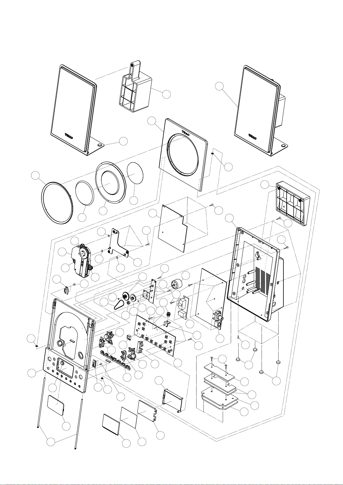
4 EXPLODED VIEWS AND PARTS LIST
3 3
EXPLODED VIEW - 1
1 1
2 2
7 7
1 1
8
42 42
16 16
19 19
15 15
17 17
6 6
5 5
4 4
12 12
11 11
9 9
12 12
1010
1010
50 50
20 20
22
16 16
23 23
22
30 30
12 12
25 25
31 31
32 32
50 50
26 26
33 33
13 13
24 24
55 55
35 35
34 34
14 14
52 52
53 53
27 27
36 36
47 47
51 51
28 28
53 53
52 52
3838
29 29
3939
53 53
37 37
52 52
4040
5959
41 41
5656
43 43
5858
48 48
54 54
54 54
43 43
5757
49 49
18 18
46 46
21 21
6
44 44
45 45

EXPLODED VIEW-1
REF. NO
1-1
1-2
PARTS NO.
19-50DX01500001
19-50DX01500020
19-50DX01500030
56-07DX0155A000
56-07DX0155B000
DESCRIPTION
SPEAKER BOX ASSY (CD-DX8)
SPEAKER BOX ASSY (MC-DX20B) [T/C]
SPEAKER BOX ASSY (MC-DX20S) [EX/M]
FULL WALL PLATE-SPEAKER - (SILVER)
FULL WALL PLATE-SPEAKER - (BLACK)
CD-X8/MC-DX20
REMARKS
1-3
1-4
1-5
1-6
1-7
1-8
1-9
1-10
1-11
1-12
1-13
1-14
1-15
1-16
1-17
1-18
1-19
1-20
1-21
1-22
1-23
1-24
1-25
56-78DX0151G000
61-68DX01500020
56-57DX01510000
57-08DX01500020
56-14DX0150A010
56-14DX0150B010
56-14DX0150A020
58-58DX01500620
20-70CMSM95B00
58-61MC23500020
58-61MC23500120
68-122301600400
56-07DX01539000
05-30DX01500000
05-30DX01510000
48-23DX0150022A
58-58DX01500420
56-57DX01532000
56-57DX01540010
56-04DX0150A010
56-04DX0150B010
56-04DX0150A020
48-23DX01500220
61-80DX01500020
58-43DX01500020
68-152402160300
56-24DX01510000
56-760000000020
CD DOOR CHROME RING
CD ALUM COVE DIA 68MM
CD DOOR LENS
CD DOOR PVC PLATE
CD DOOR - (CD-X8)
CD DOOR - (MC-DX20B) [T/C]
CD DOOR - (MC-DX20S) [EX/M]
RUBBER RING D5.4X3X1.5MM
CD MECH. (SAMSUNG) CMS-M95BG6
SHOCK ABSORBER (GREY) AC112-SI-20C
SHOCK ABSORBER- BLACK
FIBRE WASHER 3X6X0.4MM
CD BRACKET
CD(MP3) PCB ASSY (CD-X8)
CD(MP3) PCB ASSY (MC-DX20)
CLOSE SW PCB ASSY
RUBBER RING D5.4X3X1MM
REMOTE LENS
DISPLAY LENS
FRONT CABINET - (CD-X8)
FRONT CABINET - (MC-DX20B) [T/C]
FRONT CABINET - (MC-DX20S) [EX/M]
OPEN SW PCB ASSY
FERRM SHAFT 155X3MM
DRIVE BELT DIA 31X1MM
PVC WASHER D4X1.6X0.3MM
STRAP GEAR
DOOR MOTOR PULLY
1-26
1-27
1-28
1-29
1-30
1-31
1-32
1-33
1-34
1-35
1-36
1-37
1-38
1-39
1-40
1-41
56-24DX01500000
61-11DX01500320
58-44DX01500020
05-09DX01500000
56-57DX01559000
56-54DX0151A010
56-54DX0151B010
56-07DX01569000
56-53DX0151A000
56-53DX0151B000
56-57DX01569000
56-53DX0150A010
56-53DX0150B010
56-22DX0151B000
05-05DX01500000
58-61EX0M108120
56-07DX01589000
05-01DX01500000
56-05DX0150A020
56-05DX0150B010
CD DOOR GEAR
MOTOR BRACKET
MOTOR 3V
HP/AUX JACK PCB ASSY
KNOB RING-L
POWER KNOB-UNIT (SILVER)
POWER KNOB-UNIT (BLACK)
REMOTE BRACKET
CD KNOB GROUP (SILVER)
CD KNOB GROUP (BLACK)
KNOB RING-R
CD DOOR OPEN KNOB (SILVER)
CD DOOR OPEN KNOB (BLACK)
LASER COVER
KEY/DISPLAY PCB ASSY
SHOCK ABSORBER - GREY
RUBBER HOLDER
MAIN(TUNER) PCB ASSY
REAR CABINET (SILVER)
REAR CABINET (BLACK)
7

CD-X8/MC-DX20
EXPLODED VIEW-1
REF. NO
1-42
1-43
1-44
1-45
PARTS NO.
56-07DX0154A000
56-07DX0154B000
58-263102300520
13-05DX01500020
57-262392590020
DESCRIPTION
FULL WALL PLATE - UNIT (SILVER)
FULL WALL PLATE - UNIT (BLACK)
RUBBER FOOT
LCD DISPLAY
FILTER SHEET
REMARKS
1-46
1-47
1-48
1-49
1-50
1-51
1-52
1-53
1-54
1-55
1-56
1-57
1-58
1-59
56-57DX01520000
56-07DX01579000
61-11DX01500121
61-11DX01500021
66-140220160321
66-140526210321
66-140226180321
66-140226180321
66-140226210321
66-120320130321
66-120526160321
66-11DX01500420
66-11DX01500520
66-120226210321
BACK LIGHT LENS-UNIT
DISPLAY BRACKET
FERRM PLATE - HOLE (LOWER SIDE)
FERRM PLATE - SCREW HOLE (UPPER SIDE)
SCREW TA/BH 2X6MM
SCREW TA/KH 2.6X10MM
SCREW TA/BH 2.6X8MM
SCREW TA/PH 2.6X8MM
SCREW TA/BH 2.6X10MM
SCREW MS/PH 2X3MM
SCREW MS/KH 2.6X6MM
FERRM PLATE (C) 33X108X2MM (LOWER SIDE)
FERRM PLATE (D) 27X108X2MM (UPPER SIDE)
SCREW MS/BH 2.6X10MM
8
 Loading...