

D00837500A
DAW Control Surface / FireWire Audio-MIDI Interface
SETUP GUIDE

Table of Contents
1 – Introduction
About the FW-1082 .................................................................................4
COMPUTER surface mode .............................................................................. 4
MIDI CTRL (control) surface mode................................................................. 5
MON MIX (monitor mix) surface mode......................................................... 5
The IEEE 1394 standard and the FW-1082 .............................................6
Before installing the software ...............................................................7
2 – Installation (Windows 2000 and Windows XP)
System requirements..............................................................................8
Installing the software ...........................................................................9
SoftLCD............................................................................................................ 10
3 – Installation (Mac OS X 10.2.8 and above)
System requirements..............................................................................11
Installing the software ...........................................................................11
SoftLCD............................................................................................................ 11
4 – Connections
MIDI connections.....................................................................................12
Analog audio connections......................................................................12
A note on output............................................................................................ 13
Status indicators......................................................................................13
Clock source setting ................................................................................14
Other connections...................................................................................14
2 TASCAM FW-1082 Setup Guide

1 – Introduction
Figure 1.1: Mode selection keys .......................................................................4
Figure 1.2: Bank selection keys ........................................................................4
Figure 1.3: Monitor selection keys ...................................................................5
2 – Installation (Windows 2000 and Windows XP)
Figure 2.1: Windows Device Manager showing IEEE.1394 controller ...........8
Figure 2.2: Disabled IEEE.1394 controller icon ................................................8
Figure 2.3: Enabling an IEEE.1394 device in Windows ...................................9
3 – Installation (Mac OS X 10.2.8 and above)
4 – Connections
Table 4.1: Analog audio facilities ...................................................................12
Table 4.2: Specifications of analog audio I/O ................................................12
Figure 4.3: Audio output options in the Control Panel ................................13
Figure 4.4: Indicators .......................................................................................13
Figure 4.5: Clock keys and indicators .............................................................14
Table of Figures
TASCAM FW-1082 Setup Guide 3
1 – Introduction
About the FW-1082
The FW-1082 provides your computer with highquality audio facilities: eight channels of analog
input and two of output, with two channels of digital
audio I/O through coaxial connections—all at up to
96 kHz 24-bit, two physical MIDI input and two
physical output ports, together with virtual control
MIDI I/O and two virtual OUTs, and a control surface with motorized touch-sensitive faders, rotary
encoders, transport keys and dedicated digital audio
workstation function control keys.
It is connected to the host computer using a single 6pin to 6-pin IEEE 1394 cable (supplied) that carries
audio, MIDI and control information back and forth
between the FW-1082 and the computer. See “The
IEEE 1394 standard and the FW-1082” on page 6 for
details.
The control surface can pass information to the host
DAW application through the IEEE 1394 interface,
using MIDI protocol.
NOTE
Before using the FW-1082 with a computer, you must
install the necessary drivers and utility software on your
computer. See “Installation (Windows 2000 and Windows XP)” on page 8, and “Installation (Mac OS X
10.2.8 and above)” on page 11 for details of how to do
this.
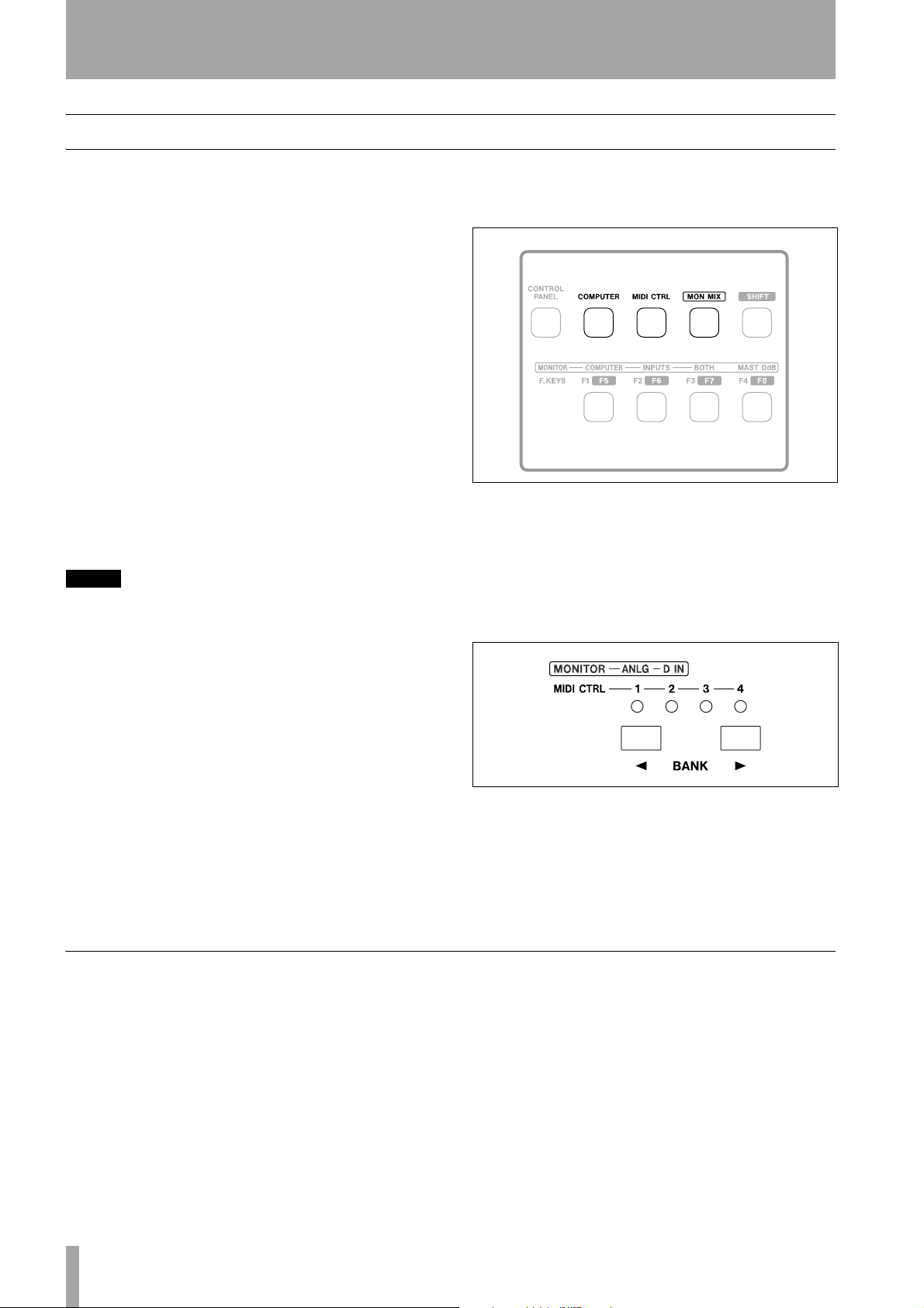
There are three main surface modes; accessed
through the mode keys as shown here (
MIDI CTRL and MON MIX).
Figure 1.1: Mode selection keys
COMPUTER,
Pressing one of these keys will light it, and put the
FW-1082 into the appropriate mode.
Although there are only eight physical channel modules fitted to the FW-1082, the
BANK keys can be
used to access different fader and module banks.
The FW-1082 can also act as a standalone dedicated
10–2 monitor mixer in one of its main modes (see
“MON MIX (monitor mix) surface mode” on page 5
for full details).
COMPUTER surface mode
In this surface mode, operating the surface controls
sends messages to the DAW software on the host
computer through the control MIDI port using the
IEEE 1394 connection.
For operations carried out in this mode to have any
effect, the FW-1082 should be connected to a host
computer with the DAW software running, and configured to accept messages from the FW-1082 control MIDI port.
Figure 1.2: Bank selection keys
Note that the banks accessed by the
BANK keys have
different meanings depending on the surface mode
selected (
COMPUTER mode); see the sections on these modes
MON MIX mode, or MIDI CTRL mode, or
for details.
The FW-1082 operates by default in its Native Mode,
typically used with dedicated control surface plugins. For those applications that do not have such a
plug-in, it can emulate the Mackie Control or HUI
protocols. The operating mode is selectable through
the software Control Panel.
See the Application Guide for full details of how to
operate the FW-1082 with your DAW software.
4 TASCAM FW-1082 Setup Guide
1 – Introduction
Two analog and/or two S/PDIF outputs are available
for output, depending on the DAW software
configuration.
MIDI CTRL (control) surface mode
In the MIDI control surface mode (MIDI CTRL), the
surface controls are mapped to MIDI control messages. The
BANK keys and indicators are used to
select up to four banks (that is, 32 modules), and the
controls can be set to transmit a different MIDI message in each bank.
This mapping of controls to messages is set up in the
FW-1082 Control Panel of the host computer, and the
process is fully described in the User’s Guide.
MIDI messages may be transmitted from the physical MIDI OUT ports, or from the virtual MIDI OUT
MON MIX (monitor mix) surface mode
In this surface mode, the FW-1082 acts as a standalone mixer, mixing up to eight analog signals
together with the two digital signals received at the
coaxial digital input.
The physical MIDI ports are usable by the DAW
application for transmitting and receiving MIDI data
to and from external MIDI equipment.
ports to the host computer (through the FireWire
cable).
When a control is mapped to a physical MIDI output
port in this mode, when the control is operated, the
appropriate
OUT indicator lights as the MIDI data is
transmitted from the FW-1082.
Note that you do not need to connect the FW-1082 to
a host computer to operate the unit in this mode with
the physical terminals—you only need to connect a
computer when you set up and map the MIDI messages.
Use the master fader to control the master stereo
level, and the
MONITOR control to adjust the level of
the signal sent to the control room monitoring system
MONITOR L and R).
(
The FW-1082 provides level, pan, mute and solo
capabilities for these input channels, mixing them
into two outputs
MONITOR (BAL) L and R.
It is also possible to monitor the signals output from
the computer DAW software, either independently, or
together with, the input signals.
Two banks are available using the
analog (
ANLG), and the stereo digital input (D IN)
BANK keys: the
banks. In the second of these, only the first two modules are active, corresponding to the stereo S/PDIF
input channels.
When mixing analog signals, the
TRIM controls can
be used to adjust the signal input levels, which can be
monitored with the overload (
tion (
SIGNAL) indicators on each module.
NOTE
When mixing digital audio, there should be one, and
only one word clock in the system. Follow the instructions in “Clock source setting” on page 14 to set the
word clock for the system.
OL) and signal detec-
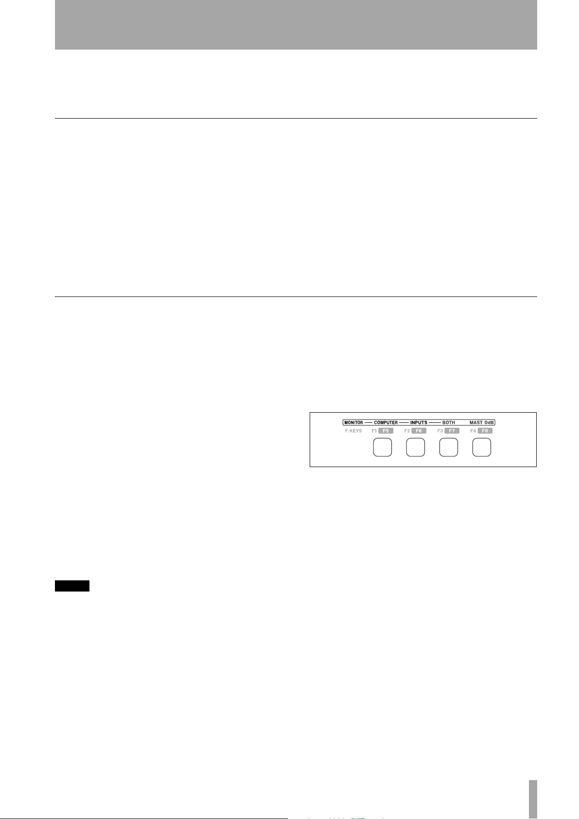
When the FW-1082 is in this mode, the three keys
shown in Figure 1.3 are used for selecting the signals
to be monitored:
Figure 1.3: Monitor selection keys
•
COMPUTER selects the signals from the DAW
passed through the FireWire connection. The level
of the signals from the computer is set using the
master output control of the DAW software and the
two analog outputs may be selected (using the software Control Panel) for output of these signals.
•
INPUTS selects the analog and coaxial signals for
monitoring.
•
BOTH allows the computer signals to be monitored
alongside the input signals
TASCAM FW-1082 Setup Guide 5

1 – Introduction
In the MON MIX mode, the fourth monitor selection
key is used for a special function. When this key
(marked as
MAST 0dB in the MONITOR row of
labels) is pressed, the master fader is moved to the
unity gain (0 dB) position.
Individual channels can be set to unity gain by pressing and holding the
channel’s
SEL key.
SHIFT key together with the
The IEEE 1394 standard and the FW-1082
The IEEE 1394 standard allows high-speed communication between devices. Because of the high bandwidth (up to 400Mbps), it is suitable for applications
such as multi-channel audio, as in the case of the
FW-1082.
NOTE
The FW-1082 is supplied with a 2 m (6-foot) cable. If you
wish to use a longer cable, the length should not be
more than 4.5 m (15 feet) and the cable should be the
best possible quality available to avoid data loss, which
results in audio dropouts.
The headphone level (
adjusted with the
PHONES jack on rear panel) is
PHONES control) and the monitor-
ing level through the monitoring outputs is set using
the
MONITOR control.
The
SOLO and MUTE channel keys in MON MIX
mode work to solo and mute the input signals associated with the channels.
There are two types of connector that may be used
with IEEE 1394 devices. One is a 6-pin connector,
and the other is a 4-pin connector (the difference
between them is that the 6-pin connector carries
power which can power external devices).
Many devices can be connected on a IEEE 1394 network. No termination is necessary on any device, and
devices identify themselves uniquely on the system,
so no ID switches, etc. need to be set.
Please note that while it is possible to “daisy-chain”
IEEE.1394 devices, the FW-1082 is a high-bandwidth device and chaining other devices with it will
very likely degrade its performance. It is therefore
strongly recommended that the FW-1082 is connected by itself on a bus. More than one 1394 connector on a computer does not mean each connector
has its own bus. More often, all connectors go to the
same bus on the computer. If you require additional
IEEE.1394 devices, it is strongly recommended that
you add a IEEE.1394 card, thus adding a separate
bus, for those devices.
CAUTION
Despite the fact that you can connect and disconnect
the FW-1082 to and from the computer with power
turned on, we strongly recommend that all connections
and disconnections are made with power to both the
FW-1082 and the computer turned off. If the DAW software is running when connections are made or broken,
it may result in your computer crashing, or “freezing”
and possible loss of data.
The cable supplied with the FW-1082 is 6-pin to 6pin—some computers are only fitted with a 4-pin
IEEE 1394 connector, and we recommend that for
full bandwidth, you use a computer with a 6-pin
IEEE 1394 connector.
NOTE
Although an IEEE 1394 connection can supply power to
some types of device, it is not possible to use such a connection to power the FW-1082.
6 TASCAM FW-1082 Setup Guide

Before installing the software
1 – Introduction
The normal precautions apply when setting up the
FW-1082:
• Make all (computer, audio and MIDI) connections
to the FW-1082 with the power turned off. See
“Connections” on page 12 for details of how to
make connections.
• Do not connect the FW-1082 to the computer until
you have installed the software.
• Handle the enclosed CD-ROM with care. If it
becomes dirty or scratched, it will be impossible
for a computer to read it, and the software cannot
be installed. If the disc becomes unreadable, a
charge will be made for its replacement, but software and documentation can be downloaded from
the TASCAM Web site.
• Do not attempt to play the enclosed CD-ROM
using an audio CD player, as this may cause damage to hearing, as well as to speakers, etc.
TASCAM FW-1082 Setup Guide 7

2 – Installation (Windows 2000 and Windows XP)
When the FW-1082 is installed on a Windows system
as described here, it provides audio ASIO 2.0, WDM
(MME) and GSIF2, including kernel level MIDI.
System requirements
Your computer should meet the specifications listed
below:
Minimum requirements: Computer running
running Windows 2000 or Windows XP and fitted
with a 6-pin IEEE 1394 (FireWire) port.
Recommended: Follow your DAW software
requirements for processor speed, memory requirements, etc.
NOTE
The FW-1082 software cannot be used with Windows
95, Windows 98 or Windows Me due to lack of full support for IEEE 1394 in these operating systems.
We strongly recommend that before the installation,
you ensure that the latest patches, service packs, etc.
are downloaded and installed, using the
Update
feature.
In addition, you should also note that your computer
must be fitted with an IEEE 1394 interface, which is
enabled. This interface should be OHCI compliant.
To check this, right-click on
desktop and select
Device Manager on the Hardware tab (see Figure
the
Properties. From there, select
My Computer on the
2.1).
Windows
You should see an item labeled IEEE 1394 Bus host
controllers
. Click the plus sign (+) next to it to
expand it.
Figure 2.1: Windows Device Manager showing
IEEE.1394 controller
The controller fitted in your system should appear as
shown in Figure 2.1, with no question marks or
crosses beside or over the icon.
8 TASCAM FW-1082 Setup Guide
Figure 2.2: Disabled IEEE.1394 controller icon

2 – Installation (Windows 2000 and Windows XP)
The example in Figure 2.2 shows a disabled controller (with a cross over it). To enable it, double-click
the controller icon, and from the
that appears, click the
General tab (Figure 2.3).
Enable Device button on the
Properties panel
Follow the instructions that appear on screen to reenable the device.
Device conflicts, etc. as shown by question marks in
the
Device Manager, are out of the scope of this
guide, and should be dealt with by reference to the
manufacturer’s documentation. In these cases, it may
be necessary to re-install drivers, etc. before the
IEEE 1394 functionality can be properly enabled.
Although this product has been checked for use with
normally configured computers which meet the specifications above, we cannot guarantee the operation
of the product, even with computers meeting the
specifications, due to differences in architecture and
implementation between computers.
Figure 2.3: Enabling an IEEE.1394 device in
Windows
Installing the software
The software installation procedure is essentially the
same for both Windows 2000 and Windows XP.
The installer program is identical for both operating
systems, and is called
yy represent major and minor revision numbers of
the software).
NOTE
You should visit the TASCAM Web site and check to see
that you have the latest version of the software for the
FW-1082. Download the latest version if necessary and
proceed with the installation.
1 Make sure the FW-1082 is NOT connected to
the computer. Connect the FW-1082 to the AC
power, but do not turn it on yet.
2 Stop all other programs on your computer,
including virus protection software.
3 Double-click on the installer program to run
it.
4 Click the
Next button. The Welcome dialog box
appears.
FW1082_WIN_x_yy.EXE (x and
5 Click the
Next button. The driver files are
installed on your hard drive.
NOTE
You may be prompted by a message informing you that
the software you are about to install does not have a
digital certificate. Simply click
installation anyway
Continue the
and proceed.
6 If you are prompted to restart your computer,
do so.
7 You can now connect the FW-1082 to the com-
puter and turn it on. The Windows Plug and
Play system detects the FW-1082 and starts
the Add New Hardware wizard, which then
discovers the needed files on its own.
8 When prompted, select the
software automatically
Install the
option, and if any
warnings appear regarding digital certificates,
etc., ignore them and select
Continue anyway.
This Plug and Play process takes around one
minute to complete.
TASCAM FW-1082 Setup Guide 9

2 – Installation (Windows 2000 and Windows XP)
The drivers are now installed and the FW-1082 is
ready to operate.
SoftLCD
In addition to the Control Panel, the installation process also installs an application called SoftLCD and
places a shortcut to it on the Desktop. This application displays the DAW messages that would be sent
to the “scribble strip”, present on some control
surfaces.
Consult the Application Notes to confirm that this
software can be used with your DAW software in the
emulation mode you choose (see the User’s Guide
for details of selecting emulation modes).
10 TASCAM FW-1082 Setup Guide

System requirements
3 – Installation (Mac OS X 10.2.8 and above)
A G3 or G4 Macintosh (including iMac, eMac,
iBook, etc.) with a FireWire port, running Mac OS X
10.2.8 or above. Consult your DAW software
requirements for RAM, processor speed, etc.
Perform the installation with the FW-1082 disconnected from the computer and turned off.
Installing the software
1 The OS X image file may be mounted directly
from the CD. If the TASCAM Web site has a
later version, download that. Within the image
file, there are two Installer packages; one to
install, and one to uninstall the FW-1082 software.
2 Double-click the
3 Enter an Administrator name and password
when prompted.
4 Follow the instructions on screen to install the
software.
5 Restart the computer if necessary.
6 When you plug in the FW-1082 after reboot-
ing the computer, the FW-1082 is recognized
by the system.
Installer package.
NOTE
The FW-1082 will NOT operate with any version of Mac
OS X prior to 10.2.8.
You should visit the TASCAM Web site and check to see
that you have the latest version of the software for the
FW-1082. Download the latest version if necessary and
proceed with the installation.
7 The Control Panel operations are described in
the User’s Guide, which allow you to set up the
Core Audio inputs and outputs for use in DAW
applications, etc.
8 Use the
Sound System Preferences Pane to
set the default inputs and outputs for the computer system.
9 You may also want to use the Apple
MIDI Setup
application to define some of the
Audio and
internal gain levels, etc. as well as defining the
MIDI setups.
NOTE
OMS and FreeMIDI, etc. are not needed under OS X, as
the FW-1082 uses the CoreMIDI features of OS X to provide the MIDI facilities of the FW-1082 system-wide.
SoftLCD
In addition to the Control Panel, the installation process also installs an application called SoftLCD in
the
/Applications directory. This application dis-
plays the DAW messages that would be sent to a
"scribble strip", present on some control surfaces.
Consult the Application Notes to confirm that this
software can be used with your DAW software in the
emulation mode you choose (see the User’s Guide
for details of selecting emulation modes).
TASCAM FW-1082 Setup Guide 11

4 – Connections
Always connect and disconnect equipment to and
from the FW-1082 with the power to all units turned
off.
When turning on power, move from source to destination (in other words, turn on the monitoring system
MIDI connections
MIDI instruments, controllers etc. should be connected with their MIDI OUTs connected to the
IN
ports of the FW-1082.
The
MIDI OUT ports of the FW-1082 should be con-
MIDI
nected to the MIDI IN ports of the external MIDI
equipment.
Analog audio connections
The eight analog input channels have the following
facilities:
Audio
channel
1
2
3
4
5
6
7
8
When connecting analog equipment, use only one of
the
MIC or LINE IN connectors—do not connect ana-
log equipment to both at the same time.
The
MIC connectors may be supplied with +48V
phantom power. This is switchable for channels 1
through 4 using the rear panel switches.
LINE MIC w/48V INSERT
Yes Yes Yes
Yes Yes Yes
Yes Yes No
Yes Yes No
Yes No No
Yes No No
Yes No No
Yes No No
Table 4.1: Analog audio facilities
last). When turning off equipment, turn off the monitoring system first, and then turn off other equipment.
This helps to prevent “thumps” that can damage your
ears, and your equipment.
NOTE
Because the IEEE 1394 cable carries all MIDI information
between the FW-1082 and the host computer, including
messages generated by the control surface and sent to
it, as well as the two virtual MIDI OUTs to the host computer, there is no need to make any MIDI connection
between the computer and the FW-1082.
The
LINE connector for channel 8 can be switched to
match the impedance of an electric guitar or bass.
WARNING
Always take care when switching the phantom power,
to ensure that devices which may be damaged if phantom power is supplied are not connected to XLR connectors where phantom power is supplied.
Microphones should not be connected to or disconnected from the FW-1082 with phantom power
switched on.
Unbalanced dynamic microphones should never be connected to phantom-powered connectors.
Analog devices such as compressors, etc. may be
connected using standard 1/4" TRS connectors with
the
INSERT jacks (channels 1 and 2). Use a special
insert “Y” cable for this, with a TRS 1/4" plug at the
foot of the Y (tip=send, ring=return), and the two
branches fitted with an unbalanced 1/4" plug.
The basic connector specifications are given here for
easy reference:
MIC LINE IN (BAL) INSERT
Connector XLR-3 type:
(1=ground, 2=hot, 3=cold)
Input level (LINE and MIC
adjustable with TRIM control)
–56 dBu to –2 dBu –42 dBu to +12 dBu (chs 1–4)
Table 4.2: Specifications of analog audio I/O
12 TASCAM FW-1082 Setup Guide
Balanced 1/4" jack:
T=hot, R=cold, S=ground
–43 dBu to +4 dBu (chs 5–8)
TRS 1/4" jack:
T=send, R=return, S=ground
–2 dBu (maximum +14 dBu)

4 – Connections
MIC LINE IN (BAL) INSERT
Output level — —
–2 dBu (maximum +14 dBu)
Input impedance 2.2 kΩ
Output impedance — — 100 Ω
Table 4.2: Specifications of analog audio I/O
a. Channel 8 can be switched to GUITAR impedance at 500 kΩ using the GUITAR | LINE/MIC switch on the rear
panel.
The MONITOR outputs are balanced (1/4" jack,
wired as for the balanced inputs), and output signals
at a nominal +4 dBu, with an impedance of 100 Ω.
These should be connected to a monitoring system.
A note on output
In the software Control Panel, there are a number of
options that you can set.
10 kΩ
a
10 kΩ
turned off (default), the master fader affects the master stereo bus level inside the DAW software, but not
the level output from the balanced outputs in monitor
mix mode).
Figure 4.3: Audio output options in the Control
Panel
The master fader can be set to control the level of the
two analog outputs in monitor mix mode (if this is
Status indicators
The four green status indicators show the current status of:
Figure 4.4: Indicators
•
PHANTOM Whether the phantom +48V power is
turned on for
•
FireWire The IEEE.1394 connection.
MIC inputs 1 through 4.
The threshold at which the
OL signal indicators light
to show an overload can be set using the control here.
It can be varied between 0.0 and –5.0 dBFS, in 0.5
dBFS increments.
Also, the S/PDIF digital outputs can be set to mirror
the analog monitor outputs (allowing you to record to
a 2-track master recorder while monitoring through
the analog outputs) or be independent of them.
•
CLOCK The system clock.
•
D IN The stereo digital input from the coaxial input.
When these indicators are lit, it means that the appropriate connection has been made and the signal is
being received properly.
A flashing
FireWire indicator shows that there is an
error in the IEEE.1394 connection.
No indicator means “no connection” for all indica-
tors except
CLOCK. If any of the other three indica-
tors are flashing fast, this shows an input error. A
slowly flashing indicator indicates a lock problem.
TASCAM FW-1082 Setup Guide 13
4 – Connections
Clock source setting
In a digital audio setup, there should be one and only
clock master.
The FW-1082 may act as the clock master for the
whole system, or it may act as a slave, taking a clock
signal from the
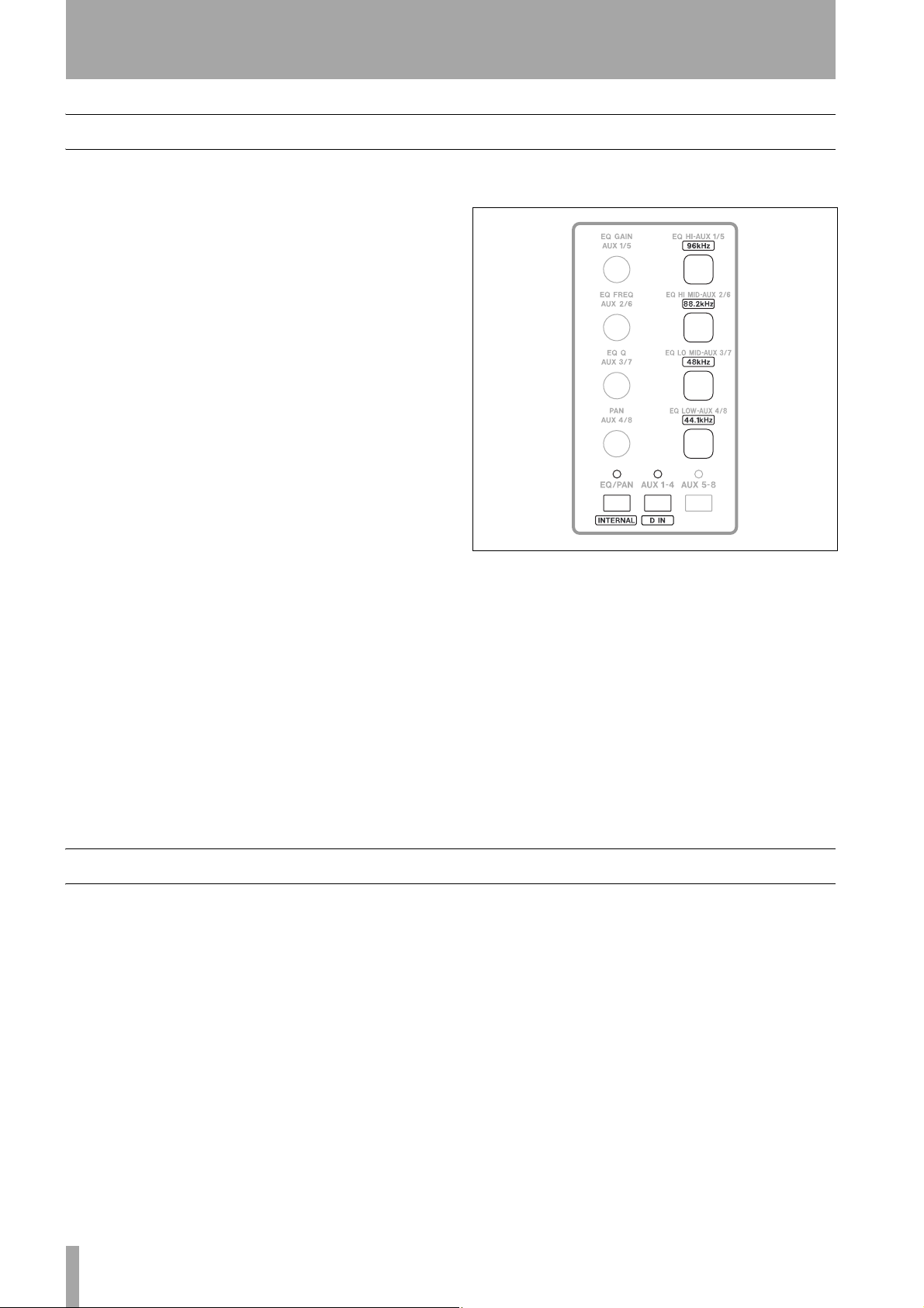
This is how you select the clock source:
1 Put the FW-1082 into
ing the
2 Press one of the clock rate keys to select the
sampling frequency:
•
96kHz (EQ HI–AUX 1/5)
• 88.2kHz (EQ HI MID–AUX 2/6)
• 48kHz (EQ LO MID–AUX 3/7)
• 44.1 kHz (EQ LOW MID–AUX 4/8)
3 Press either of the clock source keys:
INTERNAL (EQ/PAN) – Internal Clock
•
•
D IN (AUX1–4) – S/PDIF Input
When the FW-1082 is in
and source keys and indicators light to display the
COAXIAL input.
MON MIX mode by press-
MON MIX key which then lights.
MON MIX mode, these rate
current clock settings. Note that these keys have no
meaning in
As an alternative, you can use the software control
panel to select the clock source and sampling frequency:
MON MIX mode other than clock settings.
Figure 4.5: Clock keys and indicators
Other connections
Footswitch Connect an optional footswitch (e.g.
the TASCAM RC-30P) to the
FOOT SW jack).
Expected Sample Rate If the S/PDIF input is
selected as the clock source and it does not have a
usable clock signal, the
indicate a problem, and the unit switches to its own
internal clock and waits for a valid clock signal. If
the sample rate is off by 3% or more, the FW-1082
switches to the incoming clock, and the nearest sample rate LED blinks slowly.
You can use this footswitch as a punch controller
with your DAW software.
CLOCK indicator flashes to
14 TASCAM FW-1082 Setup Guide


FW-1082
TEAC CORPORATION
Phone: (0422) 52-5082 3-7-3, Nakacho, Musashino-shi, Tokyo 180-8550, Japan
TEAC AMERICA, INC.
Phone: (323) 726-0303 7733 Telegraph Road, Montebello, California 90640
TEAC CANADA LTD.
Phone: 905-890-8008 Facsimile: 905-890-9888 5939 Wallace Street, Mississauga, Ontario L4Z 1Z8, Canada
TEAC MEXICO, S.A. De C.V
Phone: 5-851-5500 Campesinos No. 184, Colonia Granjes Esmeralda, Delegaacion Iztapalapa CP 09810, Mexico DF
TEAC UK LIMITED
Phone: 01923-819699 5 Marlin House, Croxley Business Park, Watford, Hertfordshire. WD1 8TE, U.K.
TEAC EUROPE GmbH
Phone: 0611-71580 Bahnstrasse 12, 65205 Wiesbaden-Erbenheim, Germany
TEAC FRANCE S. A.
Phone: 01.42.37.01.02 17 Rue Alexis-de-Tocqueville, CE 005 92182 Antony Cedex, France
TEAC AUSTRALIA PTY.,LTD. A.B.N. 80 005 408 462
Phone: (03) 9672-2400 Facsimile: (03)9672-2249 280 William Street, Port Melbourne, Victoria 3000, Australia
TEAC ITALIANA S.p.A.
Phone: 02-66010500 Via C. Cantù 11, 20092 Cinisello Balsamo, Milano, Italy
Printed In China
 Loading...