


TEAC EXM-3 Service manual
EX-M3/MC-D3
CD Receiver System
NOTES
NOTES
CONTENTS
CONTENTS
PC board shown are viewed from parts side.
The parts with no reference number or no parts number
in the exploded views are not supplied.
As regards the resistors and capacitors, refer to the
circuit diagrams contained in this manual.
!
Parts marked with this sign are safety critical
components. they must be replaced with identical
components - refer to the appropriate parts list and
ensure exact replacement.
Parts of [ ] mark can be used only with the version designated.
[US]: U.S.A (EX-M3) [E]: EUROPE (MC-D3)
[UK]: U.K. (MC-D3)
1 SAFETY INFORMATION
2 SPECIFICATIONS
3 ADJUSTMENT AND CHECKS
4 EXPLODED VIEW AND PARTS LIST
5 PC BOARDS AND PARTS LISTS
6 WIRING DIAGRAM
7 INCLUDED ACCESSORIES
2
3
4
6
10
16
18
EX-M3/MC-D3
1 SAFETY INFORMATION
SAFETY INFORMATION
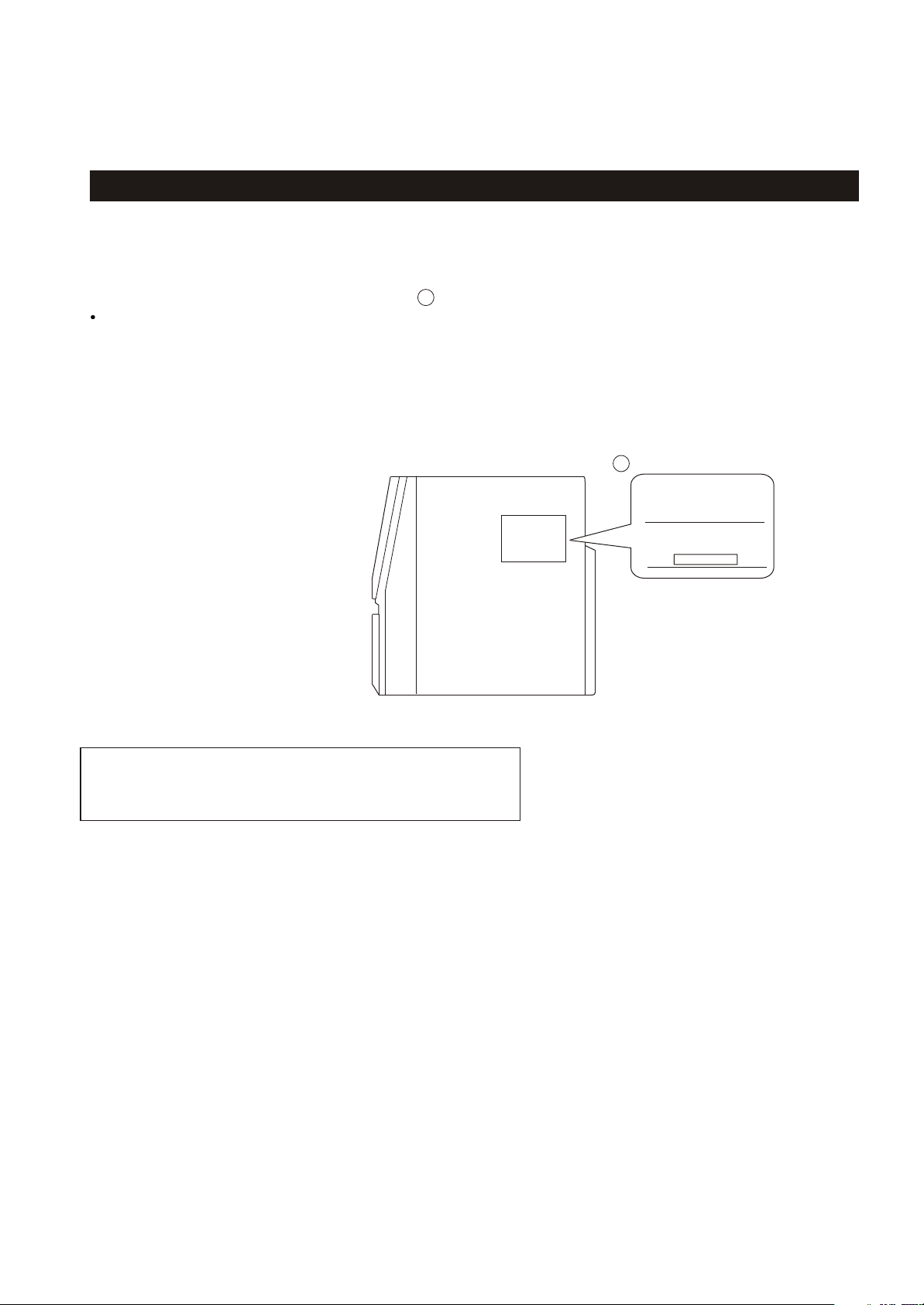
This product has been designed and manufactured according to FDA regulations " title 21, CFR, chapter 1,subchapter J,based on the
Radiation Control for Health and Safety Act of 1968" and is classified as class 1 laser product. There is not hazardous invisible laser
radiation during operation because invisible laser radiation emitted inside of this product is completely confined in the protective
housings. The label required in this regulation is shown .
CAUTION
USE OF CONTROLS OR ADJUSTMENT OR PERFORMANCE OF PROCEDURES OTHER THAN THOSE SPECIFIED HEREIN MAY RESULT IN
HAZARDOUS RADIATION EXPOSURE.
DO NOT REMOVE THE PROTECTIVE HOUSING USING SCREWDRIVER.
IF THIS PRODUCT DEVELOPS TROUBLE, MAKE A CONTACT WITH OUR SERICEMAN, AND DO NOT USE THE PRODUCT A TROUBLED STATE.
1
For U.S.A
1
CERTIFICATION
THIS PRODUCT COMPLIES WITH DHHS
RULES 21 CFR SUBCHAPTER J APPLICABLE AT DATE OF MANUFACTURE.
TEAC CORPORATION
3-7-3, NAKA-CHO, MUSASHINO-SHI, TOKYO, JAPAN
MANUFACTURED :
DATE CODE LABEL
Optical pickup:
Type : SF-P200Z
Manufacturer : SANYO Electric Co., Ltd.
Laser output : Less than 0.5 mW on the objective lens
Wavelength : 765 - 815 nm
2

CD PLAYER Section
Pickup:
Wavelength :
Audio frequency response :
CASSETTE DECK Section
Track System:
Tape Speed:
Wow and Flutter:
TUNER Section
System :
Tuning range :
EX-M3/MC-D3
2 SPECIFICATIONS
3-beam pick-up
790 nm
20 Hz ~ 22 kHz
4 track, 2 channel stereo
4.76 cm/sec
0.4% or less
PLL quartz-locked digital
synthesizer system
FM : 87.50 ~ 108.0 MHz (100kHz step) - USA
FM : 87.50 ~ 108.0 MHz (50kHz step) -EUR
AM : 530 to 1710 kHz (10 kHz step) - USA
AM : 522 to 1620 kHz (9 kHz step) - EUR
Antenna :
SPEAKER SYSTEM Section
System:
Impedance:
Dimension (W x H x D ):
146 x 233 x 200 mm
Weight:
GENERAL
Output power:
Power requirements:
Power consumption:
Dimension (W x H x D ):
Weight:
Standard Accessories:
FM pigtail antenna
AM bar antenna (built-in)
2-way shielded box
4 ohm
(5-3/4 x 9-3/16 x 7-7/8) inches
4-3/16 lb (1.9 kg) x2
15W x 2 (USA) 12.5W x 2 (EUR/UK)
120V AC, 60Hz / 230V AC, 50Hz
65W
(5-7/8 x 9-3/16 x 8-3/4) inches
150 x 233 x 223 mm
6-13/16 lb (3.1 kg)
Remote Control Unit (RC-909) x 1
Owner's Manual x 1
Warranty Card x 1
Design and specifications are subject to change without notice.
Photos and illustrations may differ slightly from production models.
3
EX-M3/MC-D3
3 ADJUSTMENTS AND CHECKS
3-1 TUNER SECTION
Use a screwdriver with a plastic or ceramic grip for all adjustment.
3-1-1 FM adjustment
1. Set the function switch to the FM position.
2. Connect the signal generator output through a 75 ohm dummy
antenna to "ANT" on MAIN PCB.
3. Connect the oscilloscope to the speaker terminal.
4. Set the signal generator as listed in the alignment chart.
3-1-2 AM adjustment
1. Set the function switch to the AM position.
2. Connect the test loop antenna across the output of the signal generator.
3. Connect the oscilloscope to the speaker terminal.
4. Set the signal generator as listed in the alignment chart.
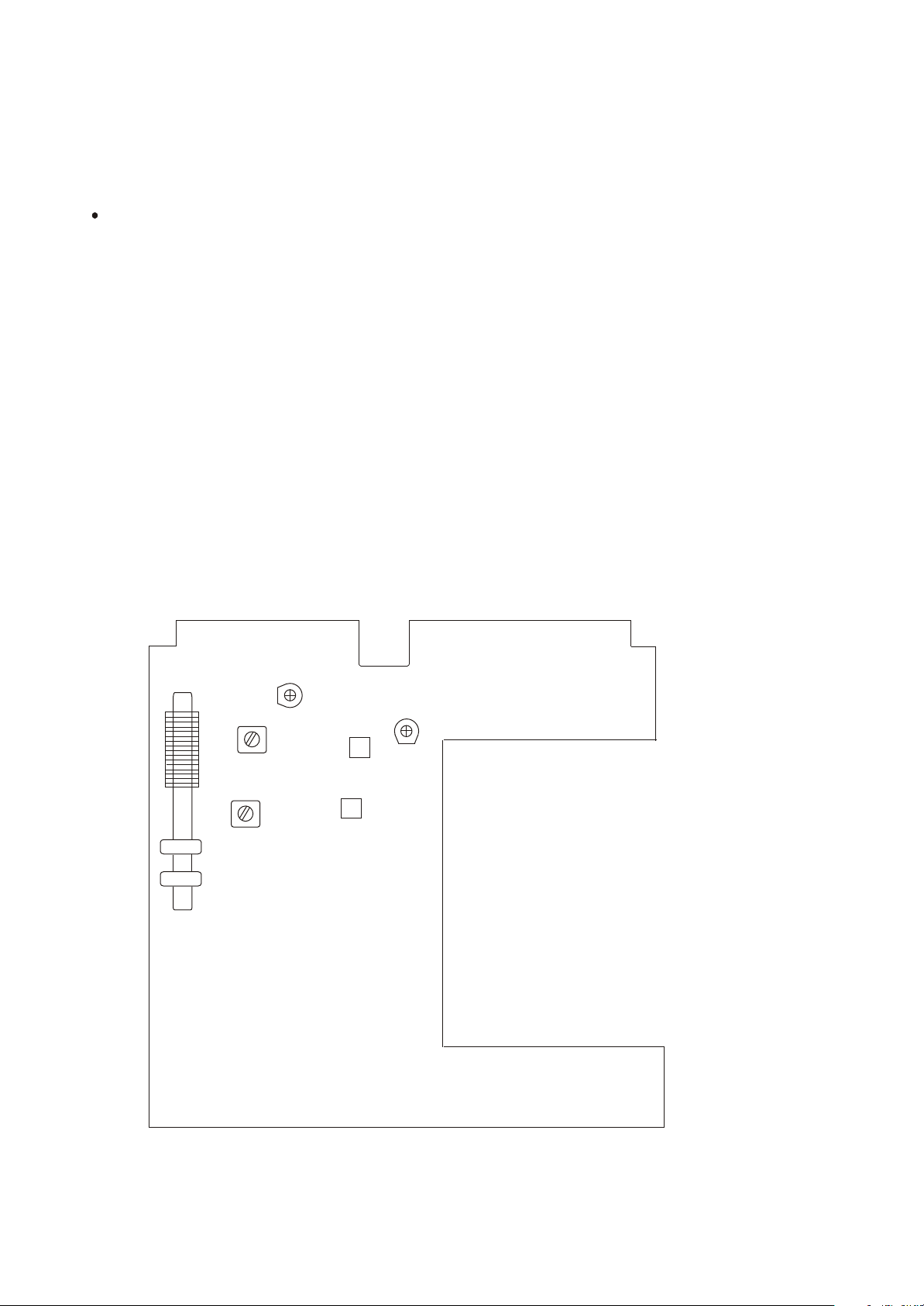
EX-M3 TUNER PCB
CT2
T2
T3
L7 AM ANT COIL
CT1
L1
L2
4
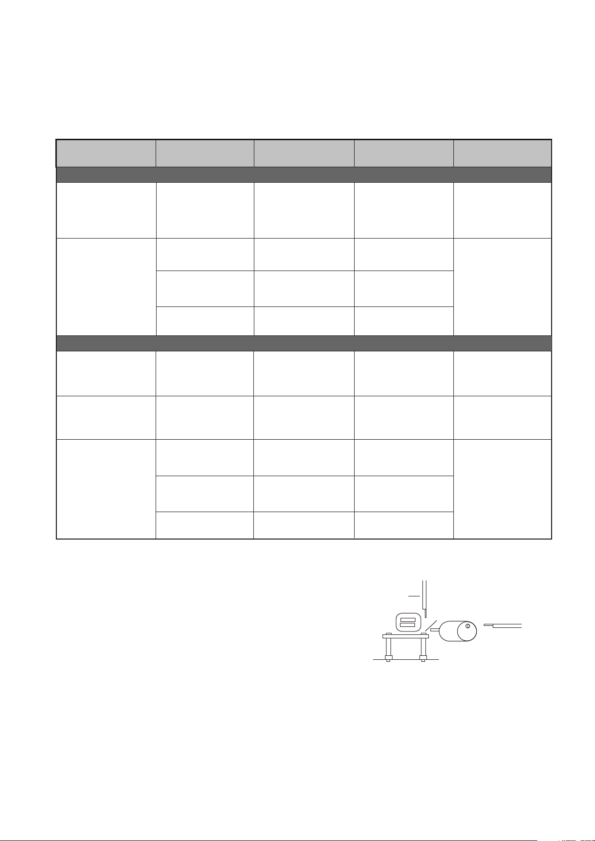
3-1-3 FM/AM alignment chart
EX-M3/MC-D3
ITEM
FM
1. FM band
2. Tracking
AM
1. IF adjustment
2. AM band
SG SETTING
87.5MHz
1kHz, +/-22.5kHz dev.
90MHz
1kHz, +/-22.5kHz dev.
106MHz
1kHz, +/-22.5kHz dev.
Repeat step 2
450kHz
1kHz, 30% mod
530kHz (USA)
522kHz (EUR/UK)
1kHz, 30% mod
TUNER SETTING
87.5MHz
90MHz
106MHz
600kHz (USA)
603kHz (EUR/UK)
530kHz (USA)
522kHz (EUR/UK)
ADJUSTMENT POINT
L2
L1
CT1
T3
T2
ADJUSTMENT
Adjust for max.output.
Adjust for max. output
and best waveform.
Adjust for max.output.
Adjust for max. output.
600kHz (USA)
3. Tracking
603kHz (EUR/UK)
1kHz, 30% mod
600kHz
1400kHz (USA)
1404kHz (EUR/UK)
1kHz, 30% mod
1400kHz
Repeat step 3
3-2 CASSETTE SECTION
1. Set the FUNCTION SELECTOR SWITCH TO TAPE.
2. Connect a Scope & VTVM across the speaker output.
3. Insert the 8KHz tape in to cassette deck and push play BUTTON.
4. ADJUST HEAD for speaker maximum output.
3-3 CD SECTION
Auto alignment.
L7
AM ANT COIL
CT2
SCREWDRIVER
Adjust for max. output
and best waveform.
ADJUSTING
SCREW
MOTOR
SCREWDRIVER
5
EX-M3/MC-D3
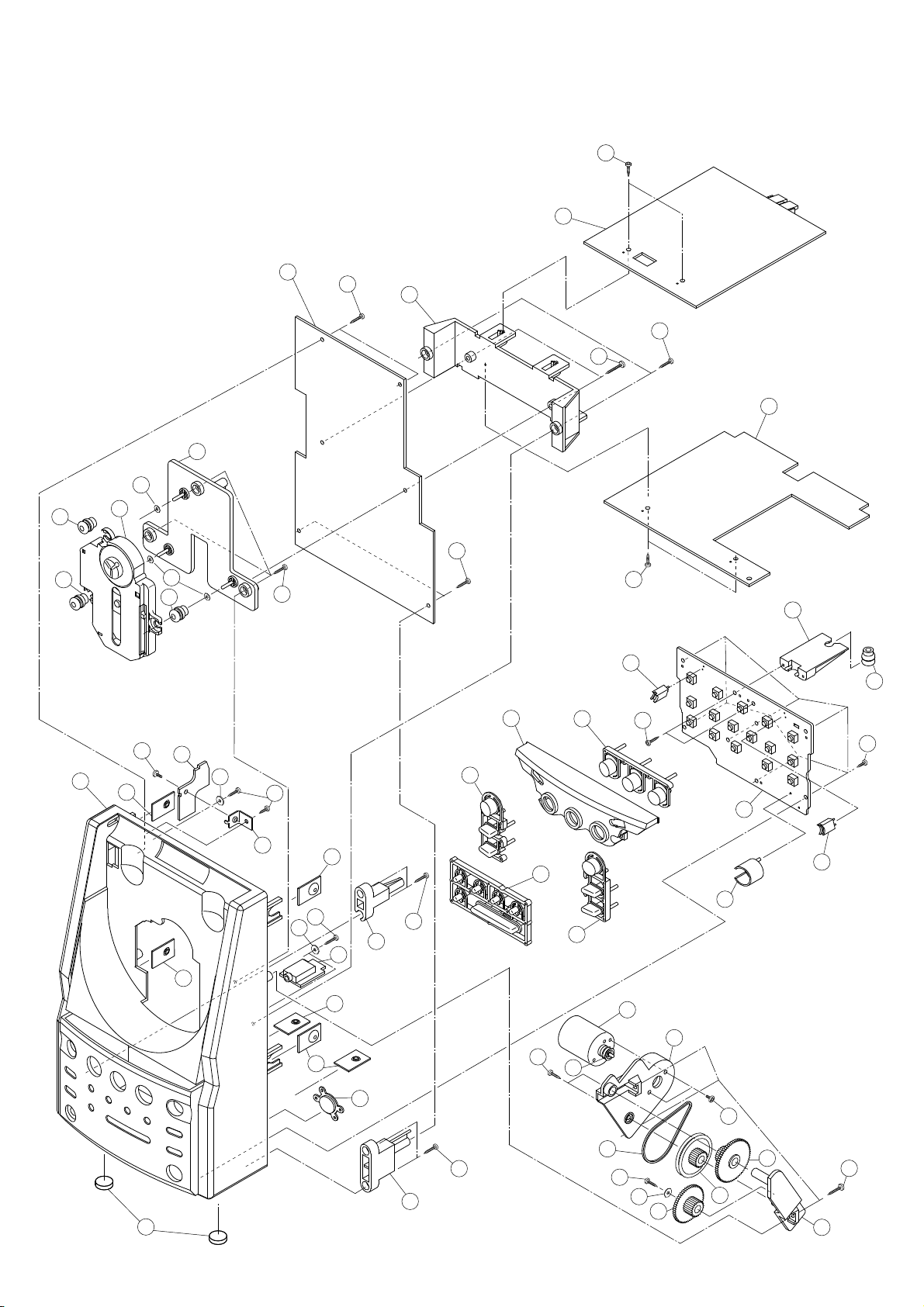
4 EXPLODED VIEWS AND PARTS LIST
13
13
14
35
13
35
15
43
EXPLODED VIEW - 1
1
43
2
43
41
3
43
40
4
41
32
31
13
29
38
5
6
7
36
41
8
7
36
43
7
7
43
33
9
7
19
11
10
41
21
12
30
41
42
16
31
17
20
22
37
18
34
43
23
42
28
24
25
26
39
27
6

EXPLODED VIEW-1
REF. NO
1-1
1-2
1-3
1-4
PARTS NO.
05-30EX0M300000
05-30EX0M300010
56-07EX0M17B000
05-07EX0M300000
05-02EX0M300000
DESCRIPTION
CD PCB ASSY - UL [US]
CD PCB ASSY - CE [E] [UK]
PCB BRACKET
POWER PCB ASSY
TUNER PCB ASSY
EX-M3/MC-D3
REMARKS
1-5
1-6
1-7
1-8
1-9
1-10
1-11
1-12
1-13
1-14
1-15
1-16
1-17
1-18
1-19
1-20
1-21
1-22
1-23
1-24
1-25
1-26
1-27
1-28
05-23EX0M100000
56-04EX0M30A010
56-04EX0M31A010
61-61D2000000020
61-11DV60000020
05-09EX0M100000
56-54EX0M33G000
56-54EX0M30A010
56-54EX0M31A010
58-61EX0M108120
20-70DA23000200
56-07EX0M12B000
05-05EX0M300000
56-07EX0M34B000
58-263122300020
56-57EX0M102000
58-44X200000020
56-760000000200
56-24EX0M13B000
58-43X200000120
56-24EX0M11B000
56-24EX0M12B000
56-24EX0M10B000
56-24EX0M14B000
68-112303100500
O/C SWITCH PCB ASSY
FRONT CABINET [US]
FRONT CABINET [E] [UK]
LOCK WASHER
PCB BRACKET
H/P PCB ASSY
VOLUME KNOB
POWER KNOB
OPEN DOOR KNOB
SHOCK ABSORBER
CD MECHANISM
CD DECK BRACKET
KEY PCB ASSY
SENSOR BRACKET
RUBBER FOOT
REMOTE LENS
CD MOTOR
DOOR MOTOR PULLY
GEAR BRACKET-A
DRIVE BELT
GEAR -B
GEAR -C
GEAR -A
GEAR BRACKET-B
METAL WASHER 3x10X0.5
1-29
1-30
1-31
1-32
1-33
1-34
1-35
1-36
1-37
1-38
1-39
1-40
1-41
1-42
1-43
56-07EX0M360010
56-54EX0M32A010
56-07EX0M389000
56-07EX0M339000
56-07EX0M329000
56-07EX0M319000
68-122301800400
66-112323101000
66-120230140321
66-120530160321
66-140230214321
66-140330216321
66-140330210321
66-140330180321
66-140330212321
LIGHT BAR
CD KNOB
LIGHT BRACKET
PCB BRACKET (C)
PCB BRACKET (B)
PCB BRACKET (A)
FIBRE WASHER 3x8x0.4
METAL WASHER 3.2x10x1
MACHINE SCREW MS/BH3x4
MACHINE SCREW MS/KH3x6
SELF-TAPPING SCREW TA/BH3x14
SELF-TAPPING SCREW TA/PH3x16
SELF-TAPPING SCREW TA/PH3x10
SELF-TAPPING SCREW TA/PH3x8
SELF-TAPPING SCREW TA/PH3x12
7
 Loading...