


 Loading...
MULTI ACCESS VIDEO DISK RECORDER
MAV-555SS (Ver. 2.32)
OPERATION MANUAL [English] 1st Edition (Revised 1)
Serial No. 10001 and Higher

WARNING
To prevent fire or shock hazard, do not expose the unit to rain or moisture.
To avoid electrical shock, do not open the cabinet. Refer servicing to qualified personnel only.
AVERTISSEMENT
Afin d’éviter tout risque d’incendie ou d’électrocution, ne pas exposer cet appareil à la pluie ou à l’humidité.
Afin d’écarter tout risque d’électrocution, garder le coffret fermé. Ne confier l’entretien de l’appareil qu’à un personnel qualifié.
WARNUNG
Um Feuergefahr und die Gefahr eines elektrischen Schlages zu vermeiden, darf das Gerät weder Regen noch Feuchtigkeit ausgesetzt werden.
Um einen elektrischen Schlag zu vermeiden, darf das Gehäuse nicht geöffnet werden. Überlassen Sie Wartungsarbeiten stets nur qualifiziertem Fachpersonal.
This symbol is intended to alert the user to the presence of important operating and maintenance (servicing) instructions in the literature accompanying the appliance.
WARNING: THIS WARNING IS APPLICABLE FOR USA ONLY.
If used in USA, use the UL LISTED power cord specified below. DO NOT USE ANY OTHER POWER CORD.
Plug Cap |
Parallel blade with ground pin |
|
(NEMA 5-15P Configuration) |
Cord |
Type SJT, three 16 or 18 AWG wires |
Length |
Less than 2.5 m (8 ft. 3 in.) |
Rating |
Minimum 10 A, 125 V |
WARNING: Using this unit at a voltage other than 120 V may require the use of a different line cord or attachment plug, or both. To reduce the risk of fire or electric shock, refer servicing to qualified service personnel.
WARNING: THIS WARNING IS APPLICABLE FOR OTHER COUNTRIES.
1.Use the approved power cord (3-core mains lead)/appliance connector/plug with earthing-contacts that conforms to the safety regulations of each country if applicable.
2.Use the power cord (3-core mains lead)/appliance connector/ plug conforming to the proper ratings (voltage, ampere).
If you have questions on the use of the above power cord/ appliance connector/plug, please consult a qualified service personnel.
AVERTISSEMENT: CET AVERTISSEMENT EST APPLICABLE AUX AUTRES PAYS.
1.Utiliser un cordon d’alimentation approuvé (conducteur d’alimentation 3 âmes)/connecteur d’appareil/prise avec contacts de mise à la terre conforme aux règles de sécurité de chaque pays si applicable.
2.Utiliser un cordon d’alimentation approuvé (conducteur d’alimentation 3 âmes)/connecteur d’appareil/prise conforme aux valeurs nominales (tension, ampérage) correctes.
S’adresser à un personnel de service qualifié pour toute question concernant l’emploi du cordon d’alimentation/connecteur d’appareil/prise ci-dessus.
WARNUNG: DIESE WARNUNG GILT FÜR ANDERE LÄNDER.
1.Verwenden Sie Netzkabel (dreiadrig), Geräteanschlüsse und Netzkabelstecker mit Masseleitung, die den Sicherheitsrichtlinien des jeweiligen Landes entspricht.
2.Verwenden Sie Netzkabel (dreiadrig), Geräteanschlüsse und Netzkabelstecker mit Masseleitung, die den vor Ort herrschenden Spannungsanforderungen (Spannung, Stromstärke) entsprechen.
Bei Fragen über die Eignung und Sicherheit von Netzkabeln (dreiadrig), Geräteanschlüssen und Netzkabelsteckern wenden Sie sich bitte an einen qualifizierten Elektrotechniker.
WARNING
THIS APPARATUS MUST BE EARTHED.
AVERTISSEMENT
CET APPAREIL DOIT ÊTRE RELIÉ À LA TERRE.
WARNUNG
DIESES GERÄT MUSS GEERDET WERDEN.

For the customers in the USA
This equipment has been tested and found to comply with the limits for a Class A digital device, pursuant to Part 15 of the FCC Rules. These limits are designed to provide reasonable protection against harmful interference when the equipment is operated in a commercial environment. This equipment generates, uses, and can radiate radio frequency energy and, if not installed and used in accordance with the instruction manual, may cause harmful interference to radio communications. Operation of this equipment in a residential area is likely to cause harmful interference in which case the user will be required to correct the interference at his own expense.
You are cautioned that any changes or modifications not expressly approved in this manual could void your authority to operate this equipment.
The shielded interface cable recommended in this manual must be used with this equipment in order to comply with the limits for a digital device pursuant to Subpart B of Part 15 of FCC Rules.
For the customers in Europe
This product with the CE marking complies with both the EMC Directive (89/336/EEC) and the Low Voltage Directive (73/23/ EEC) issued by the Commission of the European Community. Compliance with these directives implies conformity to the following European standards:
•EN60950: Product Safety
•EN55103-1: Electromagnetic Interference (Emission)
•EN55103-2: Electromagnetic Susceptibility (Immunity) This product is intended for use in the following Electromagnetic Enviroment(s):
E1 (residential), E2 (commercial and light industrial), E3 (urban outdoors) and E4 (controlled EMC environment, ex. TV studio).
Pour les clients européens
Ce produit portant la marque CE est conforme à la fois à la Directive sur la compatibilité électromagnétique (EMC) (89/ 336/CEE) et à la Directive sur les basses tensions (73/23/CEE) émises par la Commission de la Communauté européenne.
La conformité à ces directives implique la conformité aux normes européennes suivantes:
•EN60950: Sécurité des produits
•EN55103-1: Interférences électromagnétiques (émission)
•EN55103-2: Sensibilité électromagnétique (immunité)
Ce produit est prévu pour être utilisé dans les environnements électromagnétiques suivants:
E1 (résidentiel), E2 (commercial et industrie légère), E3 (urbain extérieur) et E4 (environnement EMC contrôlé, ex. studio de télévision).
Für Kunden in Europa
Dieses Produkt besitzt die CE-Kennzeichnung und erfüllt sowohl die EMV-Direktive (89/336/EEC) als auch die Direktive Niederspannung (73/23/EEC) der EG-Kommission.
Die Erfüllung dieser Direktiven bedeutet Konformität für die folgenden Europäischen Normen:
•EN60950: Produktsicherheit
•EN55103-1: Elektromagnetische Interferenz (Emission)
•EN55103-2: Elektromagnetische Empfindlichkeit
(Immunität)
Dieses Produkt ist für den Einsatz unter folgenden elektromagnetischen Bedingungen ausgelegt:
E1 (Wohnbereich), E2 (kommerzieller und in beschränktem Maße industrieller Bereich), E3 (Stadtbereich im Freien) und E4 (kontrollierter EMV-Bereich, z.B. Fernsehstudio).
Voor de Klanten in Nederland
Dit apparaat bevat een vast ingebouwde batterij die niet vervangen hoeft te worden tijdens de levensduur van het apparaat.
Raadpleeg uw leverancier indien de batterij toch vervangen moet worden. De batterij mag alleen vervangen worden door vakbekwaam servicepersoneel.
Gooi de batterij niet weg maar lever deze in als klein chemisch afval (KCA).
Lever het apparaat aan het einde van de levensduur in voor recycling, de batterij zal dan op correcte wijze verwerkt worden.
Für Kunden in Deutschland
Die in diesem Produkt verwendete Speicherbatterie muß während der Lebensdauer des Produkts nicht ausgetauscht werden.
Wenn die Batterie nach langer oder intensiver Nutzung erschöpft ist und entsorgt werden muß, wenden Sie sich bitte an den Händler, bei dem Sie das Produkt erworben haben. Um einen möglichen Kurzschluß oder elektrischen Schlag zu vermeiden, darf die Batterie nur durch qualifiziertes Kundendienstpersonal herausgenommen und ausgetauscht werden.
Entsorgen Sie die Batterie als Sondermüll. Entsorgen Sie sie nicht im normalen Müll.

Table of Contents
Chapter 1 Overview
1-1 MAV-555SS Overview...................................... |
1-1 |
|
1-2 |
Features ............................................................. |
1-1 |
1-3 |
Changes from Ver. 1.00 .................................... |
1-4 |
1-3-1 Changes from Ver. 1.00 to Ver. 2.32.......... |
1-4 |
|
1-4 |
Optional Accessories ........................................ |
1-4 |
Chapter 2
Names and Functions of
Parts
2-1 |
Front Panel ....................................................... |
2-1 |
2-1-1 Meter Panel................................................ |
2-2 |
|
2-1-2 Blank Panel................................................ |
2-6 |
|
2-2 |
System Setup Panel .......................................... |
2-6 |
2-3 |
Connector Panel ............................................... |
2-8 |
2-4 Analog Audio Expansion Box BKMA-570... |
2-11 |
|
Chapter 3 Preparations
3-1 MAV-555SS Modes........................................... |
3-1 |
||
3-2 |
Connecting External Devices ........................ |
3-10 |
|
3-2-1 Connections with the Panel Mode........... |
3-10 |
||
3-2-2 Connections with the DTR |
|
||
|
|
+ Panel Mode......................................... |
3-13 |
3-2-3 Connections with the DTR |
|
||
|
|
+ DTR Mode.......................................... |
3-15 |
3-2-4 BVE Mode Connections.......................... |
3-16 |
||
3-3 |
External Synchronization of Output Video |
|
|
|
Signals ........................................................... |
3-17 |
|
3-4 |
Setup................................................................ |
3-18 |
|
3-4-1 Basic Menu Settings ................................ |
3-18 |
||
3-4-2 |
Basic Menu Operation............................. |
3-23 |
|
3-4-3 |
Contents of the Expansion Menu ............ |
3-26 |
|
3-4-4 |
Expansion Menu Operation..................... |
3-41 |
|
3-4-5 |
System Time Settings .............................. |
3-41 |
|
3-5 |
Superimposed Character Information......... |
3-42 |
|
Chapter 4 Recording & Playback
4-1 Preparations for Recording............................. |
4-1 |
|
4-1-1 Switch Settings .......................................... |
4-1 |
|
4-1-2 Selecting the Recording Port |
|
|
|
to be Controlled ....................................... |
4-2 |
4-1-3 |
Selecting the Video Signals ....................... |
4-2 |
4-1-4 |
Selecting the Audio Signals ...................... |
4-2 |
4-1-5 |
Selecting the Video and Audio Signals |
|
|
to be Monitored........................................ |
4-2 |
4-1-6 |
Adjusting Recording Levels ...................... |
4-3 |
4-1-7 Selecting the External Device Used for |
|
|
|
Controlling Recording Operations ........... |
4-3 |
4-1-8 Recording Analog Audio ........................... |
4-3 |
|
4-2 Preparations for Playback ............................... |
4-4 |
|
4-2-1 Switch Settings .......................................... |
4-4 |
|
4-2-2 Selecting the Playback Port |
|
|
|
to be Controlled........................................ |
4-5 |
4-2-3 Selecting the Video and Audio Signals to be |
||
|
Monitored................................................. |
4-5 |
4-2-4 |
Selecting the Displayed Time Data............ |
4-5 |
4-2-5 |
Adjusting Playback Audio Levels.............. |
4-6 |
4-2-6 |
Selecting the External Device Used for |
|
|
Controlling Playback Operations ............. |
4-6 |
4-2-7 |
Remotely Controlling the Video Processor4-6 |
|
Chapter 5 Basic Functions of Each
Mode
5-1 Motion Modes ................................................... |
5-1 |
5-1-1 Changing the Motion Mode....................... |
5-1 |
5-1-2 Basic Operation with SS Mode.................. |
5-1 |
5-2 Changing the Operation Mode........................ |
5-2 |
5-3 Basic Operation with Panel Mode .................. |
5-2 |
5-3-1 Recording Operation.................................. |
5-2 |
5-3-2 Playback Operation.................................... |
5-2 |
5-3-3 EE Signal Selection ................................... |
5-3 |
5-4 Basic Operations with DTR+Panel |
|
and DTR+DTR Modes ................................... |
5-3 |
5-4-1 Initial Setup for DTR+Panel |
|
and DTR+DTR Modes............................. |
5-3 |
5-4-2 Basic Operations in DTR+Panel |
|
and DTR+DTR Modes............................. |
5-4 |
5-5 Basic Operations in BVE Mode ...................... |
5-5 |
5-5-1 Port Configuration ..................................... |
5-5 |
5-5-2 Basic Operation of the RP Port.................. |
5-5 |
5-5-3 Basic Operation of the R2 Port .................. |
5-7 |
5-5-4 Basic Operation of the P2 and P3 Ports..... |
5-7 |
5-5-5 New File Names......................................... |
5-8 |
5-5-6 Monitoring the RP Port.............................. |
5-8 |
5-5-7 Pre-roll Time .............................................. |
5-9 |
5-5-8 File Backup Function................................. |
5-9 |
5-5-9 Editing-Related Error Messages ................ |
5-9 |
Appendixes
Error Messages ..................................................... |
A-1 |
Specifications ......................................................... |
A-4 |
2 (E) Table of Contents

About This Operation Manual
This section describes the organization and use of this manual in using the Sony MAV-555SS Multi Access Video Disk Recorder. This unit is a hard disk recorder, but has the operability of a VTR, allowing easy understanding and operation by those experienced at using VTRs. Read this section to understand how the manual is put together, and determine which sections you need to read, according to your degree of experience with a VTR.
Purpose and intended audience for this manual
This operation manual describes the parts and functions of the MAV-555SS, preparations for operation, basic operations, and other essential information required for using the unit.
This unit is intended for use principally by operators in broadcasting stations and production houses. It therefore assumes that the reader has a general understanding of the operation of VTRs and other broadcast equipment. Readers well-acquainted with the operation of VTRs and hard disk recorders, after reading Chapter 2 “Names and Functions of Parts”, should be able to understand the operation of the unit, with reference to other sections as required.
However, regardless of experience level, you are recommended to read Chapter 1 “Overview” to get a grasp of the many features and functions of the unit. For first-time users of a VTR or hard disk recorder, or those with limited experience, a thorough reading of this manual is recommended.
Organization of this manual
This manual is divided into chapters as follows. The title page to each chapter also includes a summary of the chapter contents.
Chapter 1 Overview
This gives an overview of the features of the unit.
Chapter 2 Names and Functions of Parts
This lists the parts of the unit by function, with summaries of their operation.
Chapter 3 Preparations
This gives an overview of the various modes of the MAV555SS (two motion modes and four operation modes), and describes how external devices are connected according to the selected mode.
Chapter 4 Recording & Playback
This chapter describes the preparations and settings for recording and playback.
Chapter 5 Basic Functions of Each Mode
Describes basic operation of the various modes of the MAV-555SS described in Chapter 3.
Appendixes
• Error Messages
This appendix lists MAV-555SS errors and warnings that appear on the front display panel.
• Specifications
This provides the basic physical specifications, and specifications of the audio and video systems of the unit.
About This Operation Manual 3 (E)
Using this manual
Descriptions of operating procedures
The numerals attached to buttons and switches in the illustrations refer to corresponding step numbers in the operating procedure. Additionally, affected switches and indicators which should be checked are indicated.
The first time a technical term appears it is defined in a footnote. Where required, a cross-reference (in italics) shows the page in this manual or in another manual where related information may be found.
Numbers on switches etc. refer to steps in procedure
Step number in procedure
Results of a step and related information
Description of step operation
Cross-reference
3-4-2 Basic Menu Operation |
Turn the MENU control to change the setting. |
To changethe factory default settings, proceed as follows. |
Item number and name |
7 |
Display panel |
|
|
0 0 2 |
: |
C H A R |
H - P O S |
|
R1 |
P 1 |
VIDEO |
REMOTE |
|
|
|
|
INP UT |
|
|
|
|||
|
R2/P 3 |
P 2 |
|
|
|
|
|
HELP |
|
|
|
|
|
|
0 6 |
|
2 |
|
|
|
|
|
|
|
|
|
|
|
|
|
|
|
|
|
|
|
|
|
|
|
|
|
|
|
3,4,5 |
|
5 |
|
|
Setting flashes |
|
|
|
|||||||||
|
|
|
|
|
|
|
|
|
|
|
|
|
|
|
|
|
|
|
|
|
|
|
|
|
||||||||||||||||||||||
|
|
|
|
|
|
|
|
|
|
|
|
|
|
|
|
|
|
|
|
|
|
|
|
|
||||||||||||||||||||||
|
|
|
|
|
|
|
|
|
|
|
|
|
|
|
|
|
|
|
|
|
|
|
|
|
||||||||||||||||||||||
|
|
|
|
|
|
|
|
|
|
|
|
|
|
|
|
|
|
|
|
|
|
|
|
|
||||||||||||||||||||||
|
|
|
|
|
|
|
|
|
|
|
|
|
|
|
|
|
|
|
|
|
|
|
|
|
|
|
|
|
|
|
|
|
|
|
|
|
|
|
|
|
|
|
|
|||
|
|
|
|
|
|
|
|
|
|
|
|
|
|
|
|
|
|
|
|
|
|
|
|
|
|
|
|
|
|
|
|
|
|
|
|
|
setup |
|
|
|
|
|
|
|
||
|
|
|
|
|
|
|
|
|
|
|
|
|
|
|
|
|
|
|
|
|
|
|
|
|
|
|
|
|
|
|
|
|
|
|
|
|
|
|
|
|
|
|||||
|
|
1 Set theSET UPSELECT switch on thesystem |
|
When the desired setting appears, press the MENU |
|
|
|
|||||||||||||||||||||||||||||||||||||||
|
|
|
|
panel to the desired menu bank. |
|
|
|
|
|
|
|
control once more. |
|
|
Chapter |
|||||||||||||||||||||||||||||||
|
|
|
|
|
|
|
|
|
|
|
|
|
|
|
|
|
|
|
|
|
|
|
|
|
|
|
|
|
|
|
|
|
|
|
|
|
|
|
|
This confirms thesetting, and themenuitem number |
||||||
|
|
|
|
|
|
|
|
|
|
|
|
|
|
|
|
|
|
|
|
|
|
|
|
|
|
|
|
|
|
|
|
|
|
|
|
|
|
|
|
and name starts flashing again. |
3 |
|
|
|||
|
|
|
|
Note |
|
|
|
|
|
|
|
|
|
|
|
|
|
|
|
|
|
|
|
|
|
|
|
|
|
|
|
|
|
|
|
Preparations |
||||||||||
|
|
|
|
When the menu bank is modifiedafter power up, the |
|
To change settings in a menu item including a submenu, see the |
||||||||||||||||||||||||||||||||||||||||
|
|
|
|
|
section, “Menu items with submenus”. |
|||||||||||||||||||||||||||||||||||||||||
|
|
|
|
MAV-555SSmust berestartedor theFAST REBOOT |
6 |
|
|
|
|
|||||||||||||||||||||||||||||||||||||
|
|
|
|
(menu 027) on the Basic menu must be executed. |
To make other menu settings, repeat steps 3 to 5. |
|||||||||||||||||||||||||||||||||||||||||
|
|
|
|
(Changes in settings made while the power is off do |
7 When thesettings are complete, press theSET button. |
|
|
|
||||||||||||||||||||||||||||||||||||||
|
|
|
|
not becomeeffectivethenext timethepower is turned |
|
|
|
|||||||||||||||||||||||||||||||||||||||
|
|
|
|
|
|
|
|
|
|
|
|
|
|
|
CH2: Audio monitor output. Same as the Rch signal. |
|
When lit: |
|
|
|
||||||||||||||||||||||||||
|
|
|
|
on. It is necessary to start up the system a second |
|
This saves the settings, and the display returns to |
|
|
|
|||||||||||||||||||||||||||||||||||||
|
|
|
|
time.) |
|
CH3: No output. |
|
|
|
|
|
|
|
showing a time value. |
The unit is controlled from the external unit |
|||||||||||||||||||||||||||||||
|
|
|
|
|
|
|
|
|
|
|
|
|
|
|
CH4: No output. |
|
|
|
|
|
|
|
|
|
connected to the REMOTE IN (P1/P2) connector |
|||||||||||||||||||||
|
|
2 Press the MENU button. |
|
|
|
|
|
|
|
|
|
|
|
|
|
|
|
|
|
|
|
|
on the unit’s rear connector panel. |
|
|
|
||||||||||||||||||||
|
|
|
|
|
|
|
|
|
|
|
|
|
|
|
|
|
|
|
To cancel setting changes |
|
|
|
||||||||||||||||||||||||
|
|
|
|
|
|
|
|
|
|
|
|
|
|
To adjust the volume of the audio output from the |
|
When off: |
|
|
|
|||||||||||||||||||||||||||
|
|
|
|
A menu item appears in the time counter display in |
In step 7 above, before pressingthe SET button, press the |
|
|
|
||||||||||||||||||||||||||||||||||||||
|
|
|
|
|
|
|
|
|
|
|
|
|
|
PHONES jack |
|
|
|
|
|
|
MENU button. |
|
This unit is controlled from the optional control |
|||||||||||||||||||||||
|
|
|
|
the display panel.Turn the PHONES control. |
|
|
panel (BKMA-505). |
|
|
|
||||||||||||||||||||||||||||||||||||
|
|
|
|
|
|
|
|
|
Item number and name flashes |
|
|
|
|
|
|
This exits the menu mode, without saving the settings. |
|
|
|
|||||||||||||||||||||||||||
|
|
|
|
|
|
|
|
|
|
|
|
|
|
|
|
|
|
|
|
|
|
|
|
|
|
|
|
|
|
|
|
|
|
|
|
|
|
|
To change the menu display group by group |
|
|
|
||||
|
|
|
|
|
|
|
|
|
|
|
|
|
|
4-1-6 |
Adjusting |
|
|
|
|
|
|
|||||||||||||||||||||||||
|
|
|
|
|
|
|
|
|
|
|
|
|
|
Recording Levels |
4-1-8 Recording Analog Audio |
|||||||||||||||||||||||||||||||
|
|
|
|
|
|
|
0 |
0 |
2 |
: |
|
|
C |
H |
A |
R |
H |
- |
P |
O |
S |
|
|
|
|
|
|
|
|
|
|
To change the menu display group by group, press the |
|
|
|
|||||||||||
|
|
|
|
|
|
|
|
|
|
|
|
|
|
|
|
|
|
|
|
|
|
|
|
|
|
|
|
|
|
|
|
|
|
|
|
|
|
|
CHROMA button (it is not necessary to hold down the |
|
|
|
||||
|
|
|
|
|
|
|
|
|
|
|
|
|
|
|
Note |
|
|
|
|
|
|
|
|
|
|
|
|
|
|
|
|
|
|
|
|
|
|
|
||||||||
|
|
|
|
|
|
|
|
|
|
|
|
|
|
|
|
|
|
|
|
|
|
|
|
|
|
|
|
|
|
|
|
|
|
|
|
|
|
|
button). |
Using the emphasis function |
|
|
|
|||
|
|
|
|
|
|
|
|
|
|
|
|
|
|
Before |
|
performing |
|
|
the |
|
following |
|
operation,Inpleasethis state,selectturning the MENU control moves from one |
|
|
|
||||||||||||||||||||
|
|
|
|
|
|
|
|
|
|
|
|
|
|
the |
|
|
|
|
applicable |
|
|
ports. |
|
|
|
|
0 |
6 |
|
|
|
|
|
|
To record audio signals input to the ANALOG AUDIO |
|||||||||||
|
|
|
|
|
|
|
|
|
|
|
|
|
|
|
|
|
|
|
|
|
|
|
|
|
|
|
menu group to the next. To return to the MAIN MENU |
|
|
|
||||||||||||||||
|
|
|
|
|
|
|
|
|
|
|
|
|
|
|
|
|
|
|
|
|
|
|
|
|
|
|
|
|
|
|
|
|
|
|
|
|
|
|
|
|
INPUT connectors of the BKMA-570 (optional), you can |
|||||
|
|
|
|
|
|
|
|
|
|
|
|
|
|
|
|
|
|
|
|
|
|
|
|
|
|
|
|
|
|
|
|
|
|
|
|
|
|
|
display, press the CHROMA button once more, or click |
|
|
|
||||
|
|
|
|
|
|
|
|
|
|
|
|
|
|
|
|
|
|
|
|
|
|
|
|
|
|
|
|
|
|
|
|
|
|
|
|
|
|
|
the MENU control. |
use the emphasis function. |
|
|
|
|||
|
|
|
|
|
|
|
|
|
|
|
|
|
|
To |
|
adjust the |
|
recording |
|
level |
|
|
To activate the emphasis function, set EMPHASIS ON in |
|||||||||||||||||||||||
|
|
|
|
|
|
|
|
|
|
|
|
|
|
|
|
|
|
|
|
|
|
|
|
|
|
|
|
|
|
|
|
|
|
|
|
|
|
|
Modes of operatingthetheExpansionMENU controlmenu (883 and 884). |
|
|
|
||||
|
|
|
|
|
|
|
|
|
|
|
|
|
|
|
|
|
|
|
|
|
|
|
|
|
|
|
|
|
|
|
|
|
|
|
|
|
|
|
|
|
|
|||||
|
|
|
|
|
|
|
|
|
|
|
|
|
|
|
|
|
|
|
|
|
|
|
|
|
|
|
|
|
|
|
|
|
|
|
|
|
|
|
|
|
For details of the Expansion menu, s e Section 3-4-3, “Contents of |
|||||
|
|
|
|
|
|
|
|
|
|
|
|
|
|
|
|
|
|
|
|
|
|
|
|
|
|
|
|
|
|
|
|
|
|
|
|
|
|
|
|
|
||||||
|
|
|
|
|
|
|
|
|
|
|
|
|
|
When recording with a reference levelIt is possible to select either of two modes in which the |
|
|
|
|||||||||||||||||||||||||||||
|
|
|
|
|
|
|
|
|
|
|
|
|
|
|
|
|
|
|
|
|
|
|
|
|
|
|
|
|
|
|
|
|
Setting |
|
|
the Expansion Menu” (page 3-26). |
|
|
|
|||||||
|
|
|
|
|
|
|
|
|
|
|
|
|
|
Press the AUDIO REC/PB LEVEL |
adjustmentMENUcontrol,controlsooperates whenselectingitems or changing |
|
|
|
||||||||||||||||||||||||||||
|
|
|
|
|
|
|
|
|
|
|
|
|
|
that the PRESET indicator lights. The audiosettings:gnaleitheris the value changes only when you turn the |
|
|
|
|||||||||||||||||||||||||||||
|
|
|
|
|
|
|
|
|
|
|
|
|
|
|
|
|
|
|
|
|
|
|
|
|
|
|
|
|
|
|
|
|
|
|
|
|
|
|
|
|
On playback, for a signal to which emphasis has been |
|||||
|
|
3 TurntheMENU controlrecordedtoselectat the thepr setitemreferenceyouwantlevelto (showncontrol,as refeorencethe value continues changing even when you |
|
|
|
|||||||||||||||||||||||||||||||||||||||||
|
|
|
|
change. |
0 dB for an input of +4 dBm). |
stop turning. |
applied, regardless of the setting of the EMPHASIS |
|||||||||||||||||||||||||||||||||||||||
|
|
|
|
Turning the MENU control clockwise increases the |
|
|
switch, de-emphasis processing is automatically applied. |
|||||||||||||||||||||||||||||||||||||||
|
|
|
|
item number, and turning it counterclockwise |
Normally, the state is such that when you use the MENU |
|
|
|
||||||||||||||||||||||||||||||||||||||
|
|
|
|
|
|
Further, when recording digital audio signals (SDI or |
||||||||||||||||||||||||||||||||||||||||
|
|
|
|
|
|
|
|
|
|
|
|
|
|
To record with manual adjustment |
control to select items or change settings, the value |
|
|
|
||||||||||||||||||||||||||||
|
|
|
|
decreases the item number. |
|
|
|
|
|
|
|
|
|
|
|
|
|
|
|
|
|
|
|
AES/EBU), emphasis is set automatically according to the |
||||||||||||||||||||||
|
|
|
|
|
|
|
|
|
|
|
|
|
|
For each channel, press the AUDIO REC/PBchangesLEVELonly whenyouturntheMENU control (thevalue |
|
|
|
|||||||||||||||||||||||||||||
|
|
|
|
|
|
|
|
|
|
|
|
|
|
|
|
|
|
|
|
|
|
|
|
|
|
|
|
|
|
|
|
|
|
|
|
|
|
|
|
|
input signal emphasis information. With this unit, this |
|||||
|
|
|
|
|
|
|
|
|
|
|
|
|
|
adjustment control, so that the PRESET indicatorstops changinggoes off,when you stop turning). |
|
|
|
|||||||||||||||||||||||||||||
|
|
|
|
|
|
|
|
|
|
|
|
|
|
|
|
|
|
|
|
|
|
|
|
|
|
|
|
|
|
|
|
|
|
|
|
|
|
|
|
|
information cannot be changed. |
|
|
|
||
|
|
4 Press the MENUthencontroladjustonceso. that the average sound levelHowever,producesifanyoupress theSETUP/BLACK button, turning |
|
|
|
|||||||||||||||||||||||||||||||||||||||||
|
|
|
|
This allows thesettingto bechanged, and |
|
|
setting |
|
|
|
|
|
|
|
|
|||||||||||||||||||||||||||||||
|
|
|
|
value flashes. |
indication on the level metther close to the 0ondBther ferencePRESET. indicator above and to the left of the |
|
|
|
||||||||||||||||||||||||||||||||||||||
|
|
|
|
|
|
|
|
|
|
|
|
|
|
|
|
|
|
|
|
|
|
|
|
|
|
|
|
|
MENU control, the menu item or setting continues |
|
|
|
||||||||||||||
|
|
|
|
|
|
|
|
|
|
|
|
|
|
|
|
|
|
|
|
|
|
|
|
|
|
|
|
|
|
|
|
|
|
|
|
|
|
|
changing even when you stop turning. |
|
|
|
||||
|
|
|
|
|
|
|
|
|
|
|
|
|
|
Changing the display range of the audio |
|
|
|
|
|
|
||||||||||||||||||||||||||
|
|
|
|
|
|
|
|
|
|
|
|
|
|
level meters |
|
|
|
|
|
|
To stop the change when the PRESET indicator is lit, do |
|
|
|
||||||||||||||||||||||
|
|
|
|
|
|
|
|
|
|
|
|
|
|
|
|
|
|
|
|
any of the following: |
|
|
|
|
|
|
||||||||||||||||||||
|
|
|
|
|
|
|
|
|
|
|
|
|
|
By pressing the FULL/FINE button, you can switch the |
|
|
|
|
|
|
||||||||||||||||||||||||||
|
|
|
|
|
|
|
|
|
|
|
|
|
|
audio level meter display range. |
|
|
|
|
|
|
|
|
||||||||||||||||||||||||
|
|
|
|
|
|
|
|
|
|
|
|
|
|
FULL display mode: |
|
|
|
|
|
|
|
|
|
3-4 Setup 3-23 (E) |
|
|
|
|||||||||||||||||||
|
|
|
|
|
|
|
|
|
|
|
|
|
|
|
the meter display range is -60 dB to 0 dB or -40 dB to |
|
|
|
|
|||||||||||||||||||||||||||
|
|
|
|
|
|
|
|
|
|
|
|
|
|
|
+20 dB. |
|
|
|
|
|
|
|
|
|
|
|
|
|
|
|||||||||||||||||
|
|
|
|
|
|
|
|
|
|
|
|
|
|
FINE display mode: |
|
|
|
|
|
|
|
|
|
|
|
|
|
|
||||||||||||||||||
|
|
|
|
|
|
|
|
|
|
|
|
|
|
|
the meter display is enlarged, and a reference marker |
|
|
|
|
|
|
|||||||||||||||||||||||||
|
|
|
|
|
|
|
|
|
|
|
|
|
|
|
lights in the center of the meter, with the display in 0.25 |
|
|
|
|
|
|
|||||||||||||||||||||||||
|
|
|
|
|
|
|
|
|
|
|
|
|
|
|
dB steps. |
|
|
|
|
|
|
|
|
|
|
|
|
|
|
|||||||||||||||||
To select the display range in the FULL mode, use Expansion menu item 802. See Section 3-4-3, “Contents of the Expansion Menu” (page 3-26).
4-1-7 Selecting the External Device
Used for Controlling
Recording Operations
Use the following procedure to determine whether you should use the optional control panel (BKMA-505) or an external unit when recording with the MAV-555SS.
1With the PORT SELECT buttons, select the recording port to which the setting applies.
2Press the REMOTE button, turning it on or off.
Playback & Recording 4 Chapter
4-1 Preparations for Recording 4-3 (E)
Example of procedure description
4 (E) About This Operation Manual

Related manuals
The following related manuals are also available.
•Installation Manual (supplied)
This describes the installation procedure for this unit.
•Maintenance Manual (Option)
This lists basic maintenance procedures, associated accessories, electrical adjustment procedures, and how to replace the unit’s HDDs.
About This Operation Manual 5 (E)

Chapter 1 Overview
1-1 MAV-555SS Overview
The MAV-555SS is a multi-access video disk recorder that supports Super Motion Camera recording of video conforming to the MPEG-2 4:2:2 Profile@Main Level compression format, yielding an excellent image quality. The MAV-555SS is also capable of simultaneous recording of Super Motion images and playback in Sony Super Motion mode (henceforth, SS mode) or Standard Motion mode (henceforth, SD mode). These two motion modes can be selected from the setup menu. High compatibility with VTR-based editing systems is preserved by a VTR-like interface, with the added benefits of high-speed search functions and nonlinear editing made possible by hard disk recording.
In SS mode, the internal hard disk drive (henceforth, HDD) provides a maximum recording time of 6 hours and 20 minutes (30 Mbps/16-bit audio). Recording bit rates of 30, 40, or 50 Mbps can be selected. Input/output can be
configured as 1 input/1 output. The signal type is SDI (4:2:2) for video input/output. AES/EBU is available for audio input/output.
In SD mode, the HDD provides a maximum recording time of 19 hours and 20 minutes (30 Mbps/16-bit audio). Recording bit rates of 30, 40, or 50 Mbps can be selected. Input/output can be configured as 2 input/2 output, 1 input/ 3 output, or 3 input/1 input. The signal type is SDI (4:2:2) for video input/output. SDI (4:2:2) and AES/EBU are available for audio input/output.
Regardless of the motion mode, installing optional boards (BKMA-513, BKMA-570) allows the use of analog input and output.
An optional dedicated control panel (BKMA-505) is available for real-time control of recording and playback, nonlinear editing, and more.
For details about the SD and SS modes, see Section 3-1, “MAV555SS Modes” (page 3-1).
1-2 Features
■ SS mode only
Super Motion video and audio synchronized playback
In SS mode in the 1 input/1 output configuration, you can record video with an image quality 3 times sharper than normal and perform synchronized playback of video and audio.
Easy changing between the SS and SD modes
When the MAV-555SS is not in SS mode, it is possible to change to SD mode from the setup menu and perform normal operations in 2 input/2 output, 1 input/3 output, and 3 input/1 output configurations.
Material sharing between modes
In SD mode, you can play back (at 1/3 speed) and edit material recorded in SS mode.
Compatible with two different Super Slow cameras
The MAV-555SS simultaneously supports three SDI inputs from the BVP-9500WS System (Sony Super Motion Camera System) and provides one SDI Super Motion output. It can do the same for the Philips LDK23 Camera System. Switch between these two formats from the setup menu.
Overview 1 Chapter
1-1 MAV-555SS Overview / 1-2 Features 1-1 (E)

Overview 1 Chapter
Flexible I/O Configuration Possible
Various I/O and control panel options are set according to the external equipment that is connected and the operating environment. The standard input and output configurations of the unit and when various optional boards are installed are shown below.
I/O signals |
Configuration for standard |
|
|
equipment and when using |
|
|
optional boards |
|
|
|
|
SDI video |
Standard |
|
|
|
|
AES/EBU digital |
Standard |
|
audio |
|
|
|
|
|
Composite analog |
• BKMA-513 (AD/DA converter board) |
|
video |
|
is needed |
|
• |
1 output only |
|
|
|
Analog audio (four |
• BKMA-570 (analog audio expansion |
|
channels) |
|
unit) is needed |
|
• BKMA-513 (AD/DA converter board) |
|
|
|
is needed |
|
|
|
Time codes |
• |
Standard |
|
|
|
For details on the basic options, refer to Section 1-4, “Optional Accessories” (page 1-4).
■ Common to SS and SD modes
Compliance with MPEG-2 4:2:2 Profile @ Main Level
This unit records video with intraframe compression conforming to the MPEG-2 4:2:2 Profile @ Main Level standard. The recording bit rate can be set to 50, 40 or 30 Mbps to suit the intended video application. Maximum recording time depends on bit rate setting and selected Motion mode, as shown in the following table.
Input/output |
30 Mbps |
40 Mbps |
50 Mbps |
|
signal |
|
|
|
|
|
|
|
|
|
Audio |
16-bit |
20-bit |
20-bit |
20-bit |
|
|
|
|
|
SS mode |
6 h 20 min |
5 h 20 min |
4 h 50 min |
3 h 40 min |
|
|
|
|
|
SD mode |
19 h 20 min |
16 h |
14 h 40 min |
11 h 20 min |
|
|
|
|
|
For details about the SD and SS modes, see Section 3-1, “MAV555SS Modes” (page 3-1).
High grade AES/EBU digital audio as standard equipment
This unit provides four independent 20-bit/16-bit AES/ EBU digital audio signals on each DSI input/output port. Further, you can record video signals and asynchronous AES/EBU digital audio signals.
Rapid response to scene searches
The design of this unit puts the emphasis on operability as a disk recorder. In particular, the unit provides VTR-like
operability and response for scene searches, while a unique shuttle system reduces frame drop-out. Variable speed playback is supported by the dedicated control panel (using the optional BKMA-505 control panel) and existing external controllers provide jog, variable, and shuttle control with operability and response comparable to that of a VTR. Digital jog sound is supported, allowing audio segments to be found quickly and easily.
Scene searches and other editing operations on framebased material files can be carried out rapidly and accurately.
To enhance its function as a disk recorder, high speed cueup for editing points is also possible.
Real-time playback process control
Process control of audio and video inputs and outputs can be carried out in real time, using the level adjustment knob on the front panel of the unit.
Menu-driven setup
The operating conditions, initial settings for interfaces to other devices, and other settings can be controlled by menu operations on the front panel of the unit.
Nonlinear editing functions through the control panel
The optional control panel (BKMA-505) can be used to perform nonlinear editing through a user interface similar to that used for conventional VTR editing. Furthermore, independent audio channel editing is possible for up to 4 channels.
Note
Version 2.30 or later is required for the control panel (BKMA-505).
Broad range of information displays
The large display panel displays information on the operation of each of the ports (maximum four) in this unit. The displays include timecode values, error messages, setup menu information, HDDs space used and remaining capacity, and audio levels for each port.
Plug-in printed circuit boards/HDDs
Plug-in components allow easy replacement of printed boards and HDDs, keeping maintenance simple.
Self-diagnosis functions
If a fault occurs in the system or in a HDD, the cause is diagnosed, and an error code appears on the display panel.
1-2 (E) 1-2 Features
Security
This unit provides the following functions expected of equipment in broadcasting stations.
Data protection
In case of HDD failure, RAID technology is used to ensure that data recovery is possible. For example, even if a drive fails during recording, an equivalent drive interpolates the data, allowing operation to continue.
Help function and information displays
If there are any problems in system operation, error messages appear on the front panel.
Vibration resistance
The robust construction is resistant against vibration and dust, allowing the unit to be used in vehicle-borne situations. In particular, to protect the HDDs, they are mounted in special caddies independent of the main chassis of the unit.
Rack mounting
The unit can be mounted in an EIA standard 19-inch rack (optional rack mount kit RMM-555 required).
For details of rack mounting, refer to the Installation Manual.
■ SD mode only
Multi-access, Multi-operation (Simultaneous recording/playback operations possible while recording)
One of the advantages of a hard disk recorder (such as the MAV-555SS) over a conventional VTR is the ability to simultaneously access, edit, and output material (stored as files) that is being recorded. The MAV-555SS has four input and output ports standard. Each port can record or playback one video channel and four audio channels. 2 input/2 output, 3 input/1 output, and 1 input/3 output input/output port configurations can be selected on the Setup menu. An external editor or control panel can be used to perform multiple editing/output operations simultaneously.
Flexible I/O Configuration Possible
Various I/O and control panel options are set according to the external equipment that is connected and the operating environment. The standard input and output configurations of the unit and when various optional boards are installed are shown below.
I/O signals |
Configuration for standard |
|
equipment and when using |
|
optional boards |
|
|
SDI video/audio |
Standard equipment: 2 input/2 output, 3 |
|
input/1 output, 1 input/3 output |
|
|
AES/EBU digital |
Standard equipment: 2 input/2 output, 1 |
audio |
input/3 output, 3 input/1 output |
|
|
Composite analog |
• BKMA-513 (AD/DA converter board) |
video |
is needed |
|
• Select from: 2 input/2 output, 2 input/1 |
|
output, 1 input/3 output |
|
|
Analog audio (four |
• BKMA-570 (analog audio expansion |
channels) |
unit) is needed |
|
• BKMA-513 (AD/DA converter board) |
|
is needed |
|
• Select from: 2 input/2 output, 2 input/1 |
|
output, 1 input/3 output |
|
|
Time codes |
• Standard equipment |
|
|
For details on the basic options, refer to Section 1-4, “Optional Accessories” (page 1-4).
Linear editing functions
The MAV-555SS is equipped with the “BVE mode”, an operation mode that provides the unit with linear editing capabilities. If the operation mode is switched to BVE mode, the MAV-555SS recording and playback ports are integrated, and the recorder can then be used as a recording/playback VTR. This mode allows the MAV555SS to be connected to editing machines such as the BVE-600 or the BVE-2000 as a “recorder/player”. Note that in other modes the MAV-555SS playback port can still be connected to editing machines such as the BVE-600 or the BVE-2000 as a “player”.
The following functions are supported when using the BVE mode.
•Independent audio channel editing of up to 4 channels.
•Operation of the optional MAVE-F555 editing panel and the MAVE-D555 dial panel.
•Control by LTC from a BVE editor.
•Auto Assembly editing from a BVE editor.
Ability to record asynchronous signals
By setting the standard signals of each recording port as input signals, input signals that are asynchronous with the reference signals can be recorded.
Overview 1 Chapter
1-2 Features 1-3 (E)

Overview 1 Chapter
1-3 Changes from Ver. 1.00
1-3-1 Changes from Ver. 1.00 to Ver. 2.32
Improved BVE Mode
The following improvements were made.
•Addition of the Time Tracking function (automatic/ manual).
•Ability to modify the recorder OUT point after recording is started, and the addition of the REC OFF function.
•Ability to insert text and graphics.
•Ability to edit material from a BUS signal.
•Ability to save cut point information.
•Ability to change the recording level with the Editing Fader Panel BKNE-1011, and to select the MAV-555SS (in SD mode) internal RP port or VTR for the recorder to mix or swap audio channels.
•Ability to insert video with voice over editing.
•Ability to make cuts using only the RP port.
•Addition of a function that backs up files being edited if the power to the MAV-555SS is accidentally cut.
•Ability to prohibit operations from the MAVE-F555 background port in the setup menu.
•Ability to output editing point timing pulses from the GPI to an external device.
1-4 Optional Accessories
The following optional accessories are available for the MAV-555SS.
Common to SS and SD modes
Control Panel BKMA-505
This is a dedicated control panel, which can be installed in the front blank panel of the MAV-555SS (interface cables are supplied). It controls recording, playback, and editing operations on this unit.
Control Panel Case Kit BKMA-506
This kit consists of a special case for the BKMA-505 control panel and a 10-m extension cable as a set. This kit makes it possible to use the MAV-555SS at a distance of up to 10m from the control panel.
AD/DA Converter Board BKMA-513
When this board is installed in the MAV-555SS, the input and output of analog composite video signals and analog audio signals becomes possible with the MAV-555SS.
•To be able to use analog audio, the BKMA-570 analog audio expansion unit is also necessary.
•The R3 port does not support analog input when the configuration is 3 input/1 output. Even if the BKMA513 is installed, the analog inputs and outputs are
2 input/1 output.
•Cannot input analog SS signals in SS mode.
Analog Audio Expansion Unit BKMA-570
This expansion unit connects to the AUDIO I/O ports of the MAV-555SS with the supplied interface cable, and allows the MAV-555SS to use analog audio inputs and outputs.
•The BKMA-513 AD/DA Converter Board is required for analog audio input.
Rack Mount Kit RMM-555
When attached, the MAV-555SS can be fitted into an EIA standard 19-inch rack.
SD mode only
Video Effect Board BKMA-560/
Effect Expansion Board BKMA-561
When these boards are installed in the MAV-555SS, it allows you to edit materials that employ effect transitions.
For more details about materials that employ effect transitions, see the BKMA-505 Control Panel Operation Manual.
For information about the patterns that can be used and other details, refer to the Video Effect Board BKMA-560 Operation Manual or Video Effect Board BKMA-561 Operation Manual.
Editing Panel MAVE-F555
When using the BVE editor, this editing panel can be used to perform file assignment operations, nonlinear editing operations, and operations through free ports that are not being used for editing.
Dial Panel MAVE-D555
When the MAVE-F555 is connected to the MAV-555SS, it can be used in conjunction with the MAVE-D555 and BKNE-1011 to perform BVE editing operations, such as JOG dial operations, [PLAY], [SHTL], [REW], and [FF] operations, with all the ease of conventional BVE editing. Furthermore, nonlinear editing operations that were not possible with BVE editing can also be performed.
1-4 (E) 1-3 Changes from Ver. 1.00

Editing Fader Panel BKNE-1011
This panel can be used to adjust audio levels and make effect settings when performing nonlinear editing with the MAV555SS and the MAVE-F555, MAVE-D555, or BKNE-1011.
Overview 1 Chapter
1-4 Optional Accessories 1-5 (E)

Overview 1 Chapter
1-6 (E) 1-4 Optional Accessories
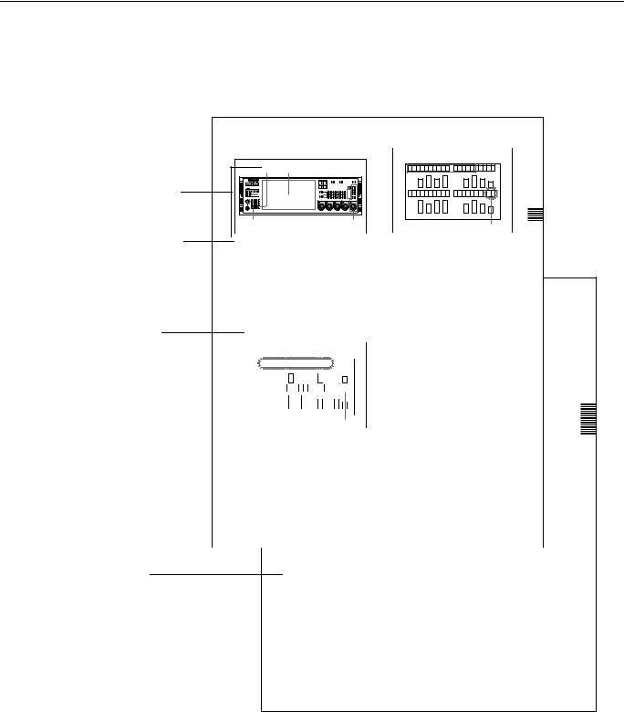
Chapter 2
Names and Functions of Parts
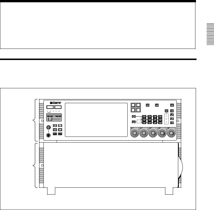
2-1 Front Panel
The front panel of the MAV-555SS is in two sections:
•Meter panel (upper)
•Blank panel (lower)
Meter panel
METER |
|
CONTROL |
||
|
PANEL |
|
PANEL |
|
525 |
625 |
SETUP BANK |
||
|
|
1 |
2 |
3 |
SYSTEM |
|
|
HDD |
|
|
|
|
HELP |
|
|
|
TOTAL / |
FULL / |
|
PHONES |
REMAIN |
FINE |
||
|
|
|
||
|
|
TC/UB |
TIMER SEL |
|
0 |
10 |
|
|
|
|
|
MENU |
SET |
|
|
|
COMPOSITE |
SDI |
|
|
|
R1 |
P1 |
VIDEO |
|
REMOTE |
||
INPUT |
|
|||||
|
|
|
|
|
||
PORT SELECT |
|
|
|
PROCESS |
|
|
R2/ |
R3/ |
|
|
|
CONTROL |
VIDEO |
P3 |
P2 |
|
|
|
|
|
|
AUDIO INPUT / MONITOR SELECT |
|
CHROMA |
|||
INPUT |
CH1 |
CH2 |
CH3 |
CH4 |
REMOTE |
|
|
|
|
|
|
|
|
|
SDI |
|
SET UP/BLACK |
|
|
MENU |
|
|
AES/EBU |
|
|
MONITOR |
|
|
|
L |
LOCAL |
CHROMA/PHASE |
|
|
|
ANALOG
R
CH1 |
CH2 |
CH3 |
CH4 |
VIDEO/MENU |
PRESET |
PRESET |
PRESET |
PRESET |
PRESET |
Blank panel
CONTROL PANEL |
SETUP |
PANEL SELECT |
CHARACTER |
SELECT |
|||
REAR FRONT |
1 2 3 |
NONE 80TH |
OFF ON |
Front panel
The blank panel in the lower part of the front panel accommodates the optional
BKMA-505 Control Panel.
For details of this control panel, see Section 1-4, “Optional Accessories” (page 1-4).
Parts of Functions and Names 2 Chapter
2-1 Front Panel 2-1 (E)
Parts of Functions and Names 2 Chapter
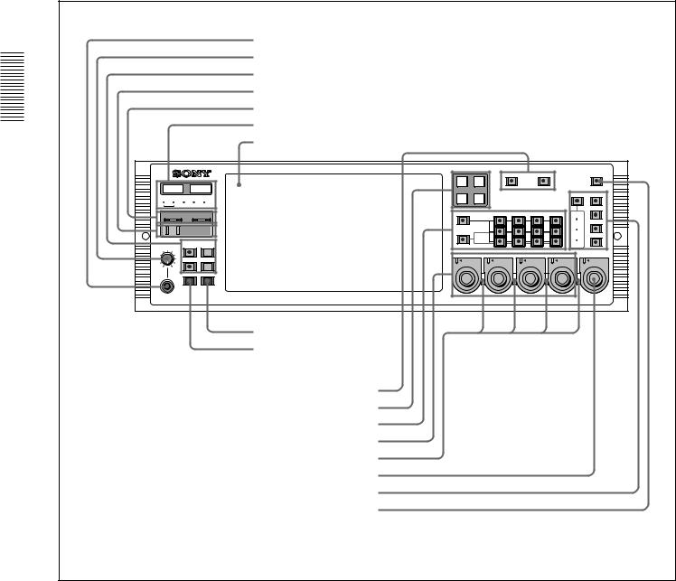
2-1-1 Meter Panel
a PHONES jack b PHONES control
c Display selection section d HELP button
e ERROR/WARNING indicators f LED indicators
g Display panel
METER |
|
CONTROL |
||
|
PANEL |
|
PANEL |
|
525 |
625 |
SETUP BANK |
||
|
|
1 |
2 |
3 |
SYSTEM |
|
|
HDD |
|
|
|
|
HELP |
|
|
|
TOTAL / |
FULL / |
|
PHONES |
REMAIN |
FINE |
||
|
|
|
||
|
|
TC/UB |
TIMER SEL |
|
0 |
10 |
|
|
|
|
|
MENU |
SET |
|
|
|
COMPOSITE |
SDI |
|
|
|
R1 |
P1 |
VIDEO |
|
REMOTE |
||
INPUT |
|
|||||
|
|
|
|
|
||
PORT SELECT |
|
|
|
PROCESS |
|
|
R2/ |
R3/ |
|
|
|
CONTROL |
VIDEO |
P3 |
P2 |
|
|
|
|
|
|
AUDIO INPUT / MONITOR SELECT |
|
CHROMA |
|||
INPUT |
CH1 |
CH2 |
CH3 |
CH4 |
REMOTE |
|
|
|
|
|
|
|
|
|
SDI |
|
SET UP/BLACK |
|
|
MENU |
|
|
AES/EBU |
|
|
MONITOR |
|
|
|
L |
LOCAL |
CHROMA/PHASE |
|
|
|
||
|
ANALOG |
|
|
|
R |
|
|
CH1 |
CH2 |
CH3 |
CH4 |
VIDEO/MENU |
PRESET |
PRESET |
PRESET |
PRESET |
PRESET |
h SET button i MENU button
j VIDEO INPUT SELECT button k PORT SELECT button l AUDIO INPUT SELECT/MONITOR SELECT section
m AUDIO REC/PB LEVEL ADJUST KNOB n PB/REC indicators o VIDEO/MENU control
p VIDEO PROCESS setting section q REMOTE button
Meter panel
2-2 (E) 2-1 Front Panel

aPHONES jack
By connecting stereo headphones with an impedance of 8 ohms to this jack, you can monitor the sound during recording, playback, and editing. This monitors the sound on the channels selected for monitor output on the currently selected port (using the PORT SELECT buttons (k) and AUDIO INPUT SELECT/MONITOR SELECT buttons (l)). Adjust the monitor volume with the PHONES control (b).
bPHONES control
This adjusts the volume of the output from the PHONES jack.
cDisplay selection section
TOTAL/REMAIN (remaining) button
Displays the total time of the files of material held on the HDD (Sys Total), the remaining available HDD capacity (Sys Remain), and the time remaining of the material currently being played/recorded for each port on the display panel (g). The button lights up when these are displayed.
FULL/FINE button
Selects the range of the audio level meter on the display panel (g) for the port currently selected by the PORT SELECT button (k).
FULL: The level meter range is -60 dB to 0 dB or -40 dB to +20 dB. A setup menu item determines which of these ranges is used (peak value 0 dB or +20 dB).
FINE: The level meter display range is magnified, to display 0.25 dB steps. If the audio level goes above the maximum display range, the top segment flashes; if the audio level goes below the minimum display range, the bottom segment flashes.
TIMER SEL (time data display select) button
This selects the type of time data displayed on the display panel (g) for the currently selected port. When normal time data (one of LTC, VITC, TM1, and TM2) is displayed, pressing the TIMER SEL button cycles the display through the sequence LTC t VITC t TM1 t TM2 t LTC ...
When user bit values are displayed, pressing the TIMER SEL button toggles between LTC and VITC user bit information.
TC/UB (timecode/user bits) button
When this button is pressed, turning it on, the user bit information in the timecode signal on the currently selected port appears on the display panel.
When the TIMER SEL selection being displayed is LTC or VITC, then the user bit information from the corresponding timecode signal is displayed.
Pressing the TC/UB button again when the user bit information is displayed turns the button off, and returns the display to normal timecode (i.e. not the user bits).
dHELP button
If a fault occurs in the system (either Error or Warning level), press this button to display details of the problem on the display panel. If more than one error or warning condition exists simultaneously, press the HELP button repeatedly to step through the corresponding displays.
After displaying the error/warning information, the operation mode of the unit and the cumulative operating times appear on the display panel in sequence. Pressing the HELP button when no fault has occurred displays only this information.
eERROR/WARNING indicators
SYSTEM indicator
If a fault occurs in the system (either Error or Warning level), this indicator flashes red. During normal operation it lights green. When it is flashing red, you can press the HELP button (d) to display details of the problem on the display panel.
HDD indicator
This indicator flashes green during access to the HDD. If a fault (either Error or Warning level) occurs in a HDD, this indicator flashes red. When it is flashing red, you can press the HELP button (d) to display details of the problem on the display panel.
When the ERROR/WARNING indicator blinks red, refer to the “Error Messages” appendix (page A-1).
fLED indicators
Operating panel indicators
These indicate which control panel can be operated: the METER PANEL indicator refers to the unit’s meter panel, and the CONTROL PANEL indicator refers to the optional control panel (BKMA-505). Each indicator lights independently when the corresponding panel is enabled, and goes off when the panel is disabled. Further, operable panel settings can be enabled through the unit’s system setup panel.
525/625 indicators
One of these lights, to show the number of scan lines in the television standard selected by basic menu item 010 (NTSC: 525 scan lines, 59.94 Hz field frequency; PAL: 625 scan lines, 50 Hz field frequency).
MENU BANK indicators
The indicator lights that corresponds to the currently valid SETUP MENU BANK. The SETUP MENU BANK is selected from the unit’s system set up panel.
Parts of Functions and Names 2 Chapter
2-1 Front Panel 2-3 (E)
All the LED indicators light when reading from or saving to the memory card.
For details, refer to Section 2-2, “System Setup Panel” (page 2-6).
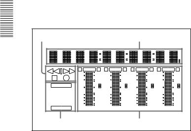
g Display indicators panel
The display panel provides four sets of identical information, for each of the ports which can be used. The following figure shows one of these displays.
|
Status indication |
|
|
|
|
Time data indication |
|
|
|||||
2 Chapter |
|
|
|
|
|
|
|
|
|
|
|
|
|
Names |
|
E |
OVER |
E |
E |
OVER |
E |
E |
OVER |
E |
E |
OVER |
E |
|
0 |
|
20 |
0 |
|
20 |
0 |
|
20 |
0 |
|
20 |
|
|
|
dB |
|
2 |
dB |
|
2 |
dB |
|
2 |
dB |
|
2 |
|
|
-10 |
|
10 |
-10 |
|
10 |
-10 |
|
10 |
-10 |
|
10 |
|
REC INHI |
|
|
1 |
|
|
1 |
|
|
1 |
|
|
1 |
and |
-20 |
|
-1 |
-20 |
|
-1 |
-20 |
|
-1 |
-20 |
|
-1 |
|
LTC VITC UB |
|
|
|
|
|||||||||
|
|
|
0 |
|
0 |
|
0 |
|
0 |
||||
ofFunctions |
TM1 TM2 |
-30 |
|
-10 |
-30 |
|
-10 |
-30 |
|
-10 |
-30 |
|
-10 |
-40 |
|
-20 |
-40 |
|
-20 |
-40 |
|
-20 |
-40 |
|
-20 |
||
|
REMOTE LOCAL |
|
|
-2 |
|
|
-2 |
|
|
-2 |
|
|
-2 |
|
-60 |
|
-40 |
-60 |
|
-40 |
-60 |
|
-40 |
-60 |
|
-40 |
|
|
READY |
|
CH15 |
dB |
|
CH26 |
dB |
|
CH37 |
dB |
|
CH48 |
dB |
Parts |
Indicators |
|
|
|
|
Audio level meters |
|
|
|||||
|
|
|
|
|
|
|
|
|
|
|
|
|
|
Time data indication
This shows time data value for the corresponding port. When you press the MENU button it also shows setup menu items, and information about Error/ Warning states.
Status indication
This shows the operating status of the port, as follows.
Play................................................................. |
B |
Stopped........................................................... |
x |
Recording ...................................................... |
z |
Variable speed playback (FWD) |
|
at less than 1× speed....................................... |
B |
Variable speed playback (REV) |
|
at less than 1× speed....................................... |
b |
Fast forward or variable speed playback |
|
exceeding 1× speed ........................................ |
BB |
Rewind or variable speed reverse playback |
|
exceeding 1× speed ........................................ |
bb |
Indicators
These show the type of timecode displayed, the remote/local setting, whether recording is inhibited, and so forth.
• REC INHIBIT
This appears when recording is inhibited on a recording port. The recording inhibit setting is carried out by a setup menu item.
• Time data type
This appears as LTC, VITC, TM1, or TM2, according to the type of time data currently being displayed. When user bits from LTC or VITC are displayed, the UB indicator also appears.
• Remote/local setting
This shows whether the port is set to LOCAL or REMOTE.
• Port status
When the port is operating normally, the READY indicator appears.
Audio level meters
These show the audio levels for each of the channels for the currently displayed port (either recording levels or playback levels as appropriate). When playing back material recorded with emphasis on, the “E” indicator appears for the corresponding channel. Either the FULL mode display (with two possible range selections) or the FINE mode display is available. To change the FULL/FINE selection, use the FULL/FINE button in the display selection section (c). Setup menu items determine the scale and headroom settings.
hSET button
Press this button after changing a setup menu item.
iMENU button
Pressing this button lights the indicator, and displays a setup menu item. Press once again to clear the menu display without changing the setting.
jVIDEO INPUT SELECT buttons
Press one of these buttons, turning it on, to select the video input signal to the currently selected port. SDI: Selects the serial digital video signal input to the
SDI INPUT connector.
COMPOSITE: Selects the analog composite video signal input to the VIDEO INPUT (COMPOSITE) connector.
kPORT SELECT buttons
These select the port used for time data display, audio/video input source selection, and other settings. The port selected by these buttons also determines the port output from MONITOR OUTPUT.
lAUDIO INPUT SELECT/MONITOR SELECT section
AUDIO INPUT SELECT/MONITOR SELECT buttons
Select the input audio signals or monitor output signals for the selected port. When the INPUT SELECT button is lit select the input audio signals, and when the MONITOR SELECT button is lit select the monitor output signals.
INPUT SELECT button
Select the type and channel of the audio signal input to the currently selected port. Press this button, turning it on, then press the required AUDIO INPUT/
2-4 (E) 2-1 Front Panel

MONITOR SELECT button to assign the type and channel.
SDI (CH1 to CH4): Select audio signals input to the SDI INPUT connectors.
AES/EBU (CH1 to CH4): Select audio signals input to the AUDIO INPUT connectors.
ANALOG (CH1 to CH4): Select the audio signals that were input at the BKMA-570’s ANALOG AUDIO INPUT connectors.
If no signal is present on the selected channel the corresponding button will flash.
MONITOR SELECT buttons
Select the audio signals monitored on the MONITOR OUTPUT L and R connectors. Press these buttons, turning them on, then press selected of the AUDIO INPUT/MONITOR SELECT buttons to assign channels to the MONITOR OUTPUT L and R outputs. If you assign more than one of the channels (channels 1 to 4) to the same monitor output channels, the channels are mixed to form the monitor output.
mAUDIO REC (recording)/PB (playback) LEVEL controls
These adjust the recording or playback levels for each of the four channels on the currently selected port. If the currently selected port is a recording port, these control the recording level, and if a playback port, the playback level. To make an adjustment, first push in the knob, so that the PRESET indicator goes off. While the PRESET indicator is lit, the level is fixed at the preset value, and cannot be adjusted.
nPB/REC indicators
These light red when the currently selected port is a recording port, and green when the currently selected port is a playback port.
oVIDEO/MENU control
While the indicator of the MENU button (i) is lit, this is used to select an item in the setup menu. For menu operation, please refer to Section 3-4, “Setup”. While the indicator of the MENU button is off, this carries out the VIDEO PROCESS adjustment according to the VIDEO PROCESS setting mode currently selected in the VIDEO PROCESS setting section (p). The adjustment is only possible if both of the following conditions are met:
•The VIDEO PROCESS control mode is set to LOCAL
•The PRESET indicator to the top left of the knob is off
While the PRESET indicator is lit, the preset value for the currently selected VIDEO PROCESS setting mode is used, and adjustment is not possible. By pushing in the knob, the PRESET indicator goes off, and adjustment is then possible.
pVIDEO PROCESS setting section
The four buttons on the right (VIDEO GAIN, CHROMA LEVEL, SETUP LEVEL/BLACK LEVEL, and CHROMA PHASE) are used to select the corresponding VIDEO PROCESS setting modes. Press one of the buttons, lighting the indicator, which shows that the corresponding VIDEO PROCESS setting mode is selected. The actual adjustment in each VIDEO PROCESS setting mode is made with the VIDEO PROCESS control (o). This adjustment applies only to the currently selected playback port.
VIDEO GAIN button
Press this button, lighting the indicator, to allow the VIDEO PROCESS control (o) to control the video output level. The current setting of the video output level appears around the control knob.
CHROMA LEVEL button
Press this button, lighting the indicator, to allow the VIDEO PROCESS control (o) to control the chrominance output level. The current setting of the chrominance output level appears around the control knob.
SETUP LEVEL/BLACK LEVEL button
Press this button, lighting the indicator, to allow the VIDEO PROCESS control (o) to control the setup level (black level). The current setting of the setup level (black level) appears around the control knob.
CHROMA PHASE button
Press this button, lighting the indicator, to allow the VIDEO PROCESS control (o) to control the hue (burst and chrominance relative phase). The current setting of the hue appears around the control knob. The button on the left (the PROCESS CONTROL button) and the three indicators (the PROCESS CONTROL MODE indicators) are used to set and indicate the VIDEO PROCESS control mode.
PROCESS CONTROL button
This sets the VIDEO PROCESS control mode for the selected port. Each time you press the button, the control mode cycles through REMOTE, MENU, LOCAL, REMOTE, and so on. The current mode is shown by the PROCESS CONTROL MODE indicators.
PROCESS CONTROL MODE indicators
These show the current VIDEO PROCESS control mode for the selected port.
REMOTE: The internal digital video processor is controlled with the HD Digital Video Controller HKDV-503/900 (sold separately).
MENU: Indicates that the internal video processor is under control of the Setup menu.
Parts of Functions and Names 2 Chapter
2-1 Front Panel 2-5 (E)
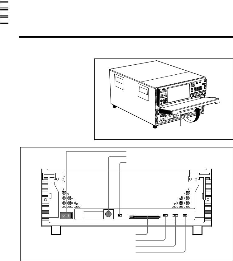
Parts of Functions and Names 2 Chapter
LOCAL: The internal video processor is controlled by the VIDEO PROCESS control (o) on this unit.
qREMOTE button
This switches the currently selected port between the REMOTE and LOCAL modes. The button lights in REMOTE mode, and goes off in LOCAL mode.
REMOTE: This unit is controlled by the device connected to the REMOTE IN connector.
LOCAL: This unit is controlled only from the optional BKMA-505 Control Panel.
2-1-2 Blank Panel
The blank panel in the lower part of the front panel accommodates the optional BKMA-505 Control Panel.
For details of this control panel, see Section 1-4, “Optional Accessories” (page 1-4).
2-2 System Setup Panel
To operate the system setup panel, raise the blank panel until it is horizontal.
System setup panel |
Accessing the system setup panel |
a POWER switch
b CONTROL PANEL connector c CONTROL PANEL switch
CONTROL PANEL |
|
|
SETUP |
PANEL SELECT |
CHARACTER |
|
|
|
SELECT |
||||
REAR FRONT |
MEMORY CARD |
ACCESS |
1 2 3 |
NONE |
BOTH |
OFF ON |
|
|
|
|
METER |
CONTROL |
|
|
|
|
|
PANEL |
PANEL |
|
d MEMORY CARD slot
e SET UP SELECT switch
f PANEL SELECT switch
g CHARACTER switch
System setup panel
2-6 (E) 2-2 System Setup Panel
aPOWER switch
Set this to the ON position to power on this unit.
bCONTROL PANEL connector
Connect an optional BKMA-505 Control Panel.
cCONTROL PANEL switch
This selects whether an optional control panel is connected to the connector on the front panel or to the connector on the rear panel. If there are control panels connected to both connectors, this switch determines which is enabled.
FRONT: Enables the control panel connected to the connector on the front panel.
REAR: Disables the control panel connected to the connector on the front panel.
dMEMORY CARD slot
Insert the memory card (sold separately) in this slot. Settings made on the Setup menu can be saved and read on a memory card as required.
To remove the card, press the eject button next to the slot.
Note
Do not eject the memory card while the ACCESS lamp is lit as this may damage the information on the memory card.
eSET UP SELECT switch
This selects the number of the menu bank for this unit’s settings. The menu bank selected by changing the switch setting becomes effective after the unit is restarted. However, changes are not effective if made while the power is off do not become effective the next time the power is turned on. In order to make the changes effective, either cycle the power off and on again, or reboot by means of the FAST REBOOT item (item number 027) in the basic menu. The currently valid menu bank is indicated by the MENU BANK indicators. You can change the settings of the current menu bank by pressing the MENU button to display the setup menu. To change the settings of any other bank, select the bank with the SET UP SELECT
switch while the setup menu is displayed.
For details of setup menus, see Section 3-4-1, “Basic Menu Settings” (page 3-18).
fPANEL SELECT switch
This switch enables or disables each of the meter panels fitted as standard to this unit and the operation control panel. The switch settings are as follows. NONE: Both of the control panels are disabled. METER PANEL: The meter panel only is enabled. CONTROL PANEL: The control panel only is
enabled.
BOTH: Both of the control panels are enabled.
gCHARACTER switch
This switch selects whether or not timecodes and other character information is superimposed on the video signal output from the MONITOR OUTPUT connector.
ON: Superimposed information is output. OFF: Superimposed information is not output. The factory default setting is ON.
*When the basic menu item ANALOG MONITOR SUPERIMPOSE (menu 008) is set to “inhibit”, superimposition cannot be enabled from the ANALOG COMPOSITE (SUPER) connector.
Parts of Functions and Names 2 Chapter
2-2 System Setup Panel 2-7 (E)

2-3 |
Connector Panel |
|
|
|
|
|
|
|
|||||
|
a VIDEO IN (COMPOSITE) connectors |
|
|
|
i REMOTE connectors |
||||||||
|
b VIDEO OUT (COMPOSITE) connectors |
|
|
|
j AUDIO I/F connector |
||||||||
|
c AUDIO IN (AES/EBU) connectors |
|
|
|
|
k MONITOR OUT connectors |
|||||||
2Chapter |
d AUDIO OUT (AES/EBU) connectors |
|
|
|
|
l DSK IN connectors |
|||||||
|
|
|
|
|
|
|
|
|
|
m SDTI CP connectors |
|||
|
|
|
|
|
|
|
|
|
|
|
|||
Names |
|
|
|
|
|
|
|
|
|
|
|
n SDI IN connectors |
|
|
|
|
|
|
|
|
|
|
|
o SDI OUT connectors |
|||
and |
|
|
|
|
|
|
|
|
|
|
|||
|
|
|
|
|
|
|
|
|
|
|
|
|
|
Functions |
|
|
|
|
|
|
|
|
VIDEO |
IN |
OUT |
MONITOR OUT |
|
|
|
|
|
|
|
|
|
|
DSK IN |
|
SDTI CP |
|
|
of |
|
|
|
|
|
|
|
|
|
|
|
1 |
2 |
|
|
|
|
|
|
|
|
|
|
|
|
|
|
Parts |
|
|
|
|
|
|
|
|
KEY |
|
|
|
|
|
|
|
|
|
|
|
|
|
|
|
SDI IN |
SDI OUT |
|
|
|
|
|
|
|
|
|
|
|
A ––––– R1 ––––– B |
A ––––– P1 ––––– B |
||
|
VIDEO IN (COMPOSITE) |
AUDIO IN (AES/EBU) |
|
AUDIO OUT (AES/EBU) |
|
REMOTE |
MONITOR OUT |
|
|
|
|
||
|
IN –––––––– R1 –––––––– OUT |
CH1/2 ––––––– R1 ––––––– CH3/4 |
|
CH1/2 ––––––– P1 ––––––– CH3/4 |
IN1(R1) |
IN2(P1) |
IN/OUT1(VTR) |
|
|
|
|
|
|
|
|
|
|
|
|
|
|
L |
|
|
|
|
|
|
|
|
|
|
|
|
|
|
|
A ––––– R2 ––––– B |
A ––––– P2 ––––– B |
||
|
IN –––––––– R2 –––––––– OUT |
CH1/2 ––––––– R2 ––––––– CH3/4 |
|
CH1/2 ––––––– P2 ––––––– CH3/4 |
IN3(R2/P3) |
IN4(R3/P2) |
IN/OUT2(VTR) |
|
|
|
|
|
|
|
|
|
|
|
|
|
|
R |
|
|
|
|
|
|
VIDEO OUT (COMPOSITE) |
CH1/2 ––––––– R3 ––––––– CH3/4 |
|
CH1/2 ––––––– P3 ––––––– CH3/4 |
VIDEO CONTROL |
SPARE |
|
|
|
|
|
||
|
|
|
|
|
|
|
|
|
|
||||
|
A ––––––– P1 ––––––– B |
|
|
|
|
|
|
|
|
|
|
|
|
|
|
|
|
|
|
|
|
ANALOG |
SDI |
|
|
|
|
|
|
|
|
|
|
|
|
COMPOSITE (SUPER) |
|
|
|
|
|
|
|
|
|
|
|
|
|
(SUPER) |
|
|
|
|
|
|
|
REFERENCE |
|
TIME CODE IN |
|
|
REMOTE PARALLEL I/O(50P) |
|
|
A ––––– R3 ––––– B |
A ––––– P3 ––––– B |
||
|
A ––––––– P2 ––––––– B |
IN |
R1 |
R2 |
SYSTEM |
|
|
|
|||||
|
|
|
|
|
|
|
|
|
|||||
|
A ––––––– P3 ––––––– B |
|
|
TIME CODE OUT |
|
|
AUDIO I/F |
|
|
|
|
|
|
|
|
|
P1 |
P2 |
P3 |
|
|
|
|
|
|
|
|
|
|
OUT |
|
|
|
|
|
|
|
|
|
|
|
|
|
|
|
|
ETHER |
|
|
|
|
|
|
|
|
e REFERENCE connectors |
|
|
|
|
|
|
|
|
p Ground terminal |
||||
f TIME CODE IN connectors |
|
|
|
|
|
q - AC IN connector |
|
||||||
g TIME CODE OUT connectors |
|
|
|
|
|
|
|
|
|
|
|
||
h ETHERNET connector |
|
|
|
|
|
|
|
|
|
|
|
||
|
|
|
|
|
|
|
Connector panel |
|
|
|
|
|
|
2-8 (E) |
2-3 Connector Panel |
|
|
|
|
|
|
|
|
|
|
|
|

aVIDEO IN (COMPOSITE) connectors (BNC type)
Input composite video signals (when the BKMA-513 option is installed). The connectors provide a loopthrough connection. A maximum of two inputs are possible.
bVIDEO OUT (COMPOSITE) connectors (BNC type)
Output composite video signals (when the BKMA513 option is installed). A maximum of two outputs are possible.
cAUDIO IN (AES/EBU Digital Audio Input) connectors (BNC type)
These jacks input digital audio signals in the AES/ EBU format. Up to three inputs can be supported.
dAUDIO OUT (AES/EBU) connectors (BNC type)
These jacks output digital audio signals in the AES/ EBU format. Up to three outputs can be supported.
eREFERENCE connectors (BNC type)
Input a reference video signal. This may be a video signal with chrominance burst (VBS) or a monochrome video signal (VS).
The connectors provide a loop-through connection.
fTIME CODE IN (Time Code Input) connectors (BNC type)
This is the input jack that is used when recording time codes from an external device. This jack connects to the time code output jack on the external device.
The setting that indicates which of the inputs, either SYSTEM or R1 (R2), in each recording port is to be used for time code recording is make in the “LTC SELECT” expansion menu item (menu 670, 671). (However, when the configuration is 3 input/1 output, SYSTEM is always used at the R3 port.)
Note
The TIME CODE IN (SYSTEM) jack supports only a 1× time code signal. The error message “TM Warning LTC” appears if any other signal is input.
gTIME CODE OUT connectors (BNC type)
These connectors output playback time codes.
hETHERNET1) (10BaseT) connector
In order to control the MAV-555SS from an external device that is connected via Ethernet, connect this connector to the external device with an Ethernet cable.
When using a LAN cable: For safety, do not connect to the connector for peripheral device wiring that might have excessive voltage.
1)Ethernet is a registered trademark of the XEROX Corporation.
iREMOTE (Remote Control Input/Output) Connectors
REMOTE IN connector (R1, P1, R2/P3, R3/P2, SPARE)
When controlling the MAV-555SS through an external device, use the 9-pin remote control cable to connect this connector to the external device.
REMOTE IN/OUT connector (1, 2)
When controlling an external device from the MAV555SS, use the 9-pin remote control cable to connect the external device to this connector.
VIDEO CONTROL connector (D-SUB 25 pins)
When controlling the internal digital video processor from a remote location, connect the HD digital video controller HKDV-503/900 (sold separately) to this
connector.
For details, refer to the installation manual.
REMOTE PARALLEL I/O connector (D-SUB 50 pins)
The remote control signals from an external device are connected to this connector.
For details, refer to the installation manual.
jAUDIO I/F connector
Connect to the optional BKMA-570 Analog Audio
Expansion Unit.
For information on the BKMA-570 connectors, refer to Section 2-4, “Analog Audio Expansion Box BKMA-570” (page 2-11).
kMONITOR OUT connectors (BNC type, XLR- 3-31)
Output video and audio monitor signals for the port currently selected on the front panel. The XLR connectors (L/R) output the audio monitor signal, and the SDI and ANALOG connectors output a video signal including superimposed information.
Audio monitor output connectors
There are two audio outputs, L and R. The channels output are selected with the meter panel’s MONITOR SELECT buttons and AUDIO INPUT/MONITOR SELECT buttons.
Parts of Functions and Names 2 Chapter
2-3 Connector Panel 2-9 (E)

Parts of Functions and Names 2 Chapter
SDI (SUPER) connector
This outputs a serial digital video/audio signal.
The audio output signals output by this connector are as follows:
CH1: Audio monitor output. Same as the Lch signal.
CH2: Audio monitor output. Same as the Rch signal.
CH3: No output CH4: No output
If the CHARACTER switch on the system setup panel is set to ON, timecode information and menu settings appear as text superimposed on the video signal.
ANALOG (COMPOSITE) (SUPER) connector
This outputs an analog composite video signal. If the CHARACTER switch on the system setup
panel is set to ON, timecode information and menu settings appear as text superimposed on the video signal.
lDSK IN connectors
When the optional BKMA-560 is installed, the DSK VIDEO signal is input to the VIDEO connector and the DSK KEY single is input to the KEY connector.
mSDTI CP connectors
These connectors cannot be used.
nSDI IN (Serial Video/Audio Input) connectors (BNC type)
The left jack inputs serial digital video/audio signals. When the power is on, signals that are input to the jack on the right is output through an internal circuit, making a bridge connection possible in SD mode. A maximum of three inputs are available.
oSDI OUT (Serial Video/Audio Input) connectors (BNC type)
These jacks output serial digital video/audio signals. A maximum of three outputs are available.
pGround terminal
Connect to ground as required.
q- AC IN connector
Connect to a power outlet using the power cord (1- 776-997-11) (sold separately).
2-10 (E) 2-3 Connector Panel
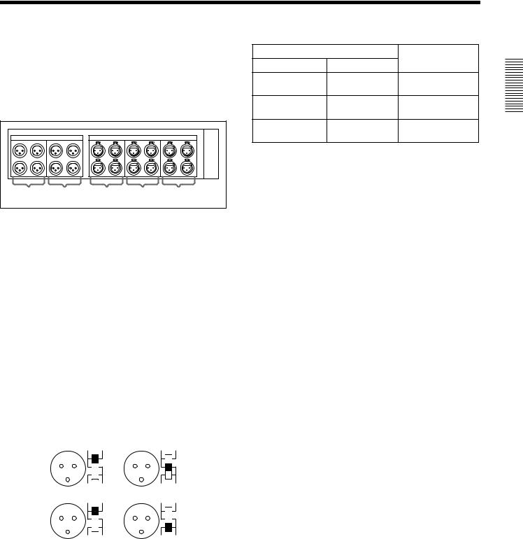
2-4 Analog Audio Expansion Box BKMA-570
When using analog audio input and output with this unit, |
|
|
|
|
||||
connect the optional Analog Audio Expansion Box |
Audio Input |
Switch Setting |
|
|||||
BKMA-570 to the AUDIO I/F connectors on the unit’s |
Level |
Impedance |
|
|||||
|
|
|||||||
connector panel, then connect to peripheral units via the |
-60 dBu |
High impedance |
LOW-OFF (lower |
|
||||
BKMA-570. |
|
|
|
|
|
|||
|
|
|
|
(microphone input) |
(approx. 20 kΩ) |
position) |
|
|
The optional BKMA-513 is necessary for analog input and |
+4 dBu (line voice |
High impedance |
HIGH-OFF (central |
|
||||
output. |
|
|
|
|
|
|||
|
|
|
|
input) |
(approx. 20 kΩ) |
position) |
|
|
|
|
|
|
|
Chapter |
|||
|
|
|
|
|
+4 dBu (line voice |
600 Ω |
HIGH-ON (upper |
|
|
|
|
|
|
|
|||
INPUT |
|
|
OUTPUT |
|
input) |
|
position) |
|
|
|
|
|
|
|
|
||
1 |
2 |
1 |
2 |
3 |
|
|
|
2 |
|
|
|
|
|
|
|
|
|
a |
b |
c |
d |
e |
|
|
|
and Names |
|
|
|
of Functions |
|||||
a INPUT 1 (R1 input) connectors (XLR-3-31) |
|
|
|
|||||
Analog audio inputs to the R1 port. |
|
|
|
|
Parts |
|||
|
|
|
|
|
||||
bINPUT 2 (R2 input) connectors (XLR-3-31)
Analog audio inputs to the R2 port.
cOUTPUT 1 (P1 output) connectors (XLR-3-32)
Analog audio outputs from the P1 port.
dOUTPUT 2 (P2 output) connectors (XLR-3-32)
Analog audio outputs from the P2 port.
eOUTPUT 3 (P3 output) connectors (XLR-3-32)
Analog audio outputs from the P3 port. (Planned for use with future functions.)
Input connectors (a and b) have LEVEL switches for each channel as shown below.
Channel LEVEL switches are set for use as follows:
CH1 |
HIGH |
ON |
CH2 |
HIGH |
ON |
|
|
|
|
||
|
LOW |
OFF |
|
LOW |
OFF |
|
LEVEL 600Ω |
|
LEVEL 600Ω |
||
CH3 |
HIGH |
ON |
CH4 |
HIGH |
ON |
|
|
|
|
||
|
LOW |
OFF |
|
LOW |
OFF |
|
LEVEL 600Ω |
|
LEVEL 600Ω |
||
2-4 Analog Audio Expansion Box BKMA-570 2-11 (E)

Chapter 3 Preparations
3-1 MAV-555SS Modes
Before using the unit, you need to select a mode according to how you want to use the MAV-555SS. The available modes are described below.
Motion modes (Two modes)
The motion modes allow you to select the MAV-555SS playback and recording speeds. When you want to record/playback at standard speed, select the SD mode (Standard Motion mode). When you want to record/playback at 3 times speed, select the SS mode (Sony Super Motion mode).
• SS mode: |
The MAV-555SS can simultaneously record signals |
|
input from Sony Super Motion or Philips cameras and |
|
perform playback at -3/3 to 3/3 speed. |
|
In SS mode, you can only use the Panel and DTR+Panel |
|
operation modes. For details, see “Operation modes” |
|
below. |
• SD mode: |
This is the mode to use under normal recording or |
|
playback conditions. It allows you to edit material |
|
recorded in SS mode and to play back such material at 1/ |
|
3 speed. In SD mode, you can use all four operation |
|
modes. For details, see “Operation modes” below. |
Operation modes (Four modes)
The operation modes allow you to select how the MAV-555SS is controlled.
There are four modes to select from.
• Panel mode: |
This mode allows you to control the MAV-555SS from |
|
the optional BKMA-505 Control Panel, Player port on |
|
the editor, or an external device. |
• DTR+Panel mode: |
Replay and slow motion playback using one camera |
|
(Replay & Slow 1). |
• DTR+DTR mode: |
Replay and slow motion playback using two cameras |
|
(Replay & Slow 2). |
• BVE mode: |
The MAV-555SS is used as a recorder VTR. |
This section contains examples of system configurations for each mode, as well as required option settings.
Select the motion mode from Basic menu item 042 PORT CONFIGURATION. Select the operation mode from Basic menu item 019 SYSTEM OPERATE CONFIGURATION. For details about the Basic menu, see Section 3-4, “Setup” (page 3-18).
For details about how to connect external devices according to the mode, see Section 3-2, “Connecting External Devices” (page 3-10).
Preparations 3 Chapter
3-1 MAV-555SS Modes 3-1 (E)
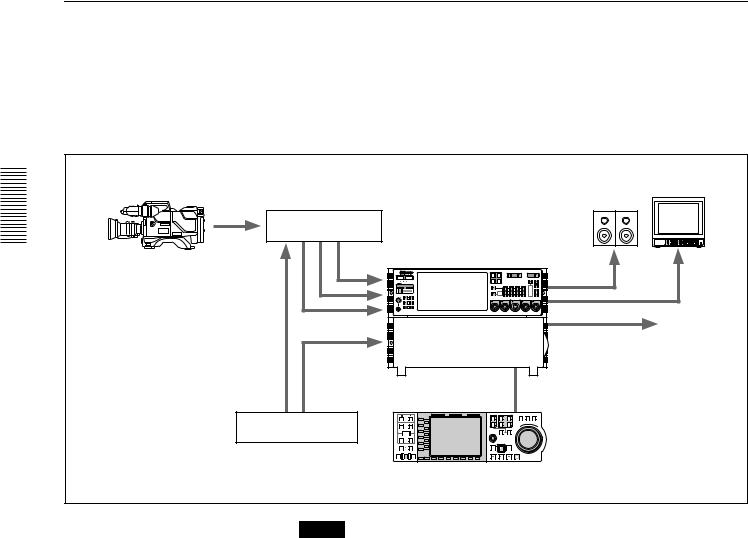
Preparations 3 Chapter
Panel Mode
SS Mode (Sony Super Motion Mode)
In this mode you can record input signals from Sony Super Motion and Philips cameras, and perform playback simultaneously. This mode allows you to select the Panel and DTR+Panel operation modes.
The following illustration shows a three SDI input and one SDI Super Motion output system form a BVP-9500WS System (Sony Digital Super Motion Camera System) connected to the MAV-555SS.
Monitor
Camera Control Unit |
|
|
|
|
CCU-900 + BKP-9330 |
|
|
|
|
Sony Super Motion |
|
|
|
|
Camera system |
P3 |
P2 |
VIDEO |
|
|
R1 |
P1 |
INPUT |
REMOTE |
|
PORT SELECT |
|
|
|
BVP-9500WS + CA950 |
R2/ |
|
|
|
HELP |
|
|
monitor output |
|
|
|
|
|
|
REF |
SDI x 3 |
|
|
|
|
|
|
|
SDI/Composite output |
|
REF |
|
|
|
|
MAV-555SS |
|
|
|
|
L1 |
|
|
|
|
|
1 |
R1 |
P1 |
Sync Generator |
L2 |
|
|
|
|
|
2 |
R2/ |
WARD |
L5 |
|
|
|
|
|
P3 |
|||
|
L3 |
|
|
|
|
|
P2 |
||
|
L4 |
|
|
|
|
|
|
|
FOR |
|
L6 |
|
|
|
|
|
|
|
|
|
L7 |
|
|
|
|
|
|
|
|
|
L8 |
|
|
|
|
|
|
|
|
|
L9 |
|
|
|
|
|
|
|
|
|
L10 |
|
|
|
|
|
|
|
|
|
L11 |
|
|
|
|
|
|
|
|
|
B1 |
B2 |
B3 |
B4 |
B5 |
B6 |
B7 |
|
|
Control Panel
BKMA-505
Note
•In SS mode, set the MAV-555SS expansion menu OUTPUT REF LOCK (menu 120) to REF, and REFFERENCE SELECT (menus 349, 350, 351) to output ref.
•In SS mode, it is necessary to adjust the MAV setting of the Camera Control Unit (CCU-900). For details about this setting, refer to the CCU-900 Installation Manual, section 1-5-4, “VPR-57 Board (BKP-9330)”.
3-2 (E) 3-1 MAV-555SS Modes
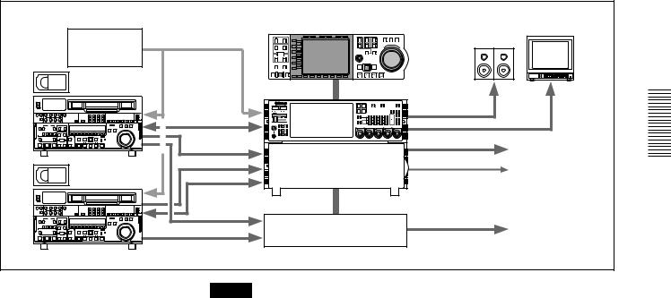
SD Mode (Standard Motion mode)
In this mode, the input and output ports are controlled independently from the optional BKMA-505 Control Panel or from the Player port of the editor. However, an external device cannot be selected as the recorder.
|
|
|
Control Panel |
|
|
|
|||||
|
|
|
|
BKMA-505 |
|
|
|
Monitor |
|||
|
|
|
PB EE |
PB |
HOLD |
RESET |
TC/UB TC TYPE |
|
|
|
|
|
|
|
|
|
|
|
|
|
|
SHUTTLE JOG |
VAR |
Sync Generator |
|
TRIM |
L1 |
|
|
|
1 |
R1 |
P1 |
|
|
|
ENTRY |
L5 |
|
|
|
MULTI |
PLAYER RECORDER |
|
RWAR |
||
|
IN |
OUT |
L2 |
|
|
|
2 |
R2/ |
P2 |
|
|
|
|
AUDIO |
L3 |
|
|
|
P3 |
|
|
||
|
|
|
L4 |
|
|
|
|
|
|
|
FO |
|
|
|
L6 |
|
|
|
CONTROL |
|
|
|
D |
|
IN |
OUT |
L7 |
|
|
|
|
|
|
|
|
|
|
|
L8 |
|
|
|
|
|
|
|
|
|
DMC EDIT DELETE |
L9 |
|
|
|
PREROLL |
REC |
EDIT |
|
|
|
|
|
|
L10 |
|
|
|
|
|
|
|
|
|
|
|
L11 |
|
|
|
|
|
|
|
|
|
PREVIEW |
AUTO EDIT REVIEW |
|
|
|
|
REW |
PLAY |
F. FWD STOP |
|
|
REF. |
REF. |
|
MODE SHIFT B1 |
B2 |
B3 B4 |
B5 |
B6 B7 |
|
|
|
|
|
|
|
|
|
|
|
|
|
|
||
|
|
|
|
|
|
|
R1 |
P1 |
VIDEO |
REMOTE |
|
|
|
|
|
|
|
|
INPUT |
|
|||
|
|
|
|
|
|
|
PORT SELECT |
|
|
|
|
|
|
|
|
|
|
|
R2/ |
P2 |
|
|
|
|
|
|
|
|
|
|
P3 |
|
|
|
|
RS 422 |
HELP |
monitor |
MENU
|
|
|
|
SDI/Composite |
|
VTR |
SDI/Composite |
|
|
LTC |
To VTR or Server |
REF. |
|
|
|
|
|
|
RS 422 |
|
SETUP |
|
|
|
CONTROL PANEL |
SELECT PANEL SELECT CHARACTER |
|
|
|
|
|
|
|
|
|
|
|
|
MAV-555SS |
|
|
|
Analog Audio |
Analog Audio Expansion Unit |
Analog Audio |
|
|
|
BKMA-570 |
|
|
|
|
|
|
|
|
|
|
VTR |
2 input/2 output configuration example |
|
|
||
Note
When editing, set expansion REFERENCE SELECT (menu 349, 350, 351) to “output ref”.
Preparations 3 Chapter
3-1 MAV-555SS Modes 3-3 (E)
Loading...