


hdc-900
Table of contents
 Loading...
HD COLOR CAMERA
HDC-900
HDC-900/L
HDC-910
HDC-910/L
HDC-930
HDC-950
HD CCD BLOCK ADAPTOR
HKC-T950
INSTALLATION AND MAINTENANCE MANUAL
1st Edition (Revised 7)
! WARNING
This manual is intended for qualified service personnel only.
To reduce the risk of electric shock, fire or injury, do not perform any servicing other than that
contained in the operating instructions unless you are qualified to do so. Refer all servicing to
qualified service personnel.
! WARNUNG
Die Anleitung ist nur für qualifiziertes Fachpersonal bestimmt.
Alle Wartungsarbeiten dürfen nur von qualifiziertem Fachpersonal ausgeführt werden. Um die
Gefahr eines elektrischen Schlages, Feuergefahr und Verletzungen zu vermeiden, sind bei
Wartungsarbeiten strikt die Angaben in der Anleitung zu befolgen. Andere als die angegeben
Wartungsarbeiten dürfen nur von Personen ausgeführt werden, die eine spezielle Befähigung
dazu besitzen.
! AVERTISSEMENT
Ce manual est destiné uniquement aux personnes compétentes en charge de l’entretien. Afin
de réduire les risques de décharge électrique, d’incendie ou de blessure n’effectuer que les
réparations indiquées dans le mode d’emploi à moins d’être qualifié pour en effectuer d’autres.
Pour toute réparation faire appel à une personne compétente uniquement.
For HDC-900/910/930/950 For HDC-900/910/930/950
CAUTION
Use of controls or adjustments or performance of
procedures other than those specified herein
may result in hazardous radiation exposure.
For HDC-900/910/930/950
Laser Diode Properties
Material : In GaAsp
Wave length : 1310 nm
Emission duration : Pulse code modulation
Laser output power : _8 dBm
HDC-900 (SY) Serial No. 10001 and Higher
HDC-900/L (J) Serial No. 30001 and Higher
HDC-910 (UCJ) Serial No. 10001 and Higher
HDC-910/L (J) Serial No. 30001 and Higher
HDC-910 (CE) Serial No. 40001 and Higher
CLASS 1
LASER PRODUCT
LASER KLASSE 1
PRODUKT
This HD color camera is classified as a CLASS 1
LASER PRODUCT.
The CLASS 1 LASER PRODUCT label is located on the
cabinet near the CCU connector.
HDC-930 (SY) Serial No. 10001 and Higher
HDC-950 (JN, SY) Serial No. 10001 and Higher
HKC-T950 (SY) Serial No. 10001 and Higher
HDC-900/950 IMM

For HDC-900/910/930/950
CAUTION
Danger of explosion if battery is incorrectly replaced.
Replace only with the same or equivalent type
recommended by the manufacturer.
Dispose of used batteries according to the
manufacturer’s instructions.
Vorsicht!
Explosionsgefahr bei unsachgemäßem Austausch
der Batterie.
Ersatz nur durch denselben oder einen vom
Hersteller empfohlenen ähnlichen Typ . Entsorgung
gebrauchter Batterien nach Angaben des
Herstellers.
ATTENTION
ADVARSEL
Lithiumbatteri - Eksplosjonsfare.
Ved utskifting benyttes kun batteri som
anbefalt av apparatfabrikanten.
Brukt batteri returneres
apparatleverandøren.
VARNING
Explosionsfara vid felaktigt batteribyte.
Använd samma batterityp eller en likvärdig typ
som rekommenderas av apparattillverkaren.
Kassera använt batteri enligt gällande
föreskrifter.
VAROITUS
Il y a danger d’explosion s’il y a remplacement
incorrect de la batterie.
Remplacer uniquement avec une batterie du même
type ou d’un type équivalent recommandé par le
constructeur.
Mettre au rebut les batteries usagées conformément
aux instructions du fabricant.
ADVARSEL!
Lithiumbatteri-Eksplosionsfare ved fejlagtig
håndtering.
Udskiftning må kun ske med batteri
af samme fabrikat og type.
Levér det brugte batteri tilbage til leverandøren.
Paristo voi räjähtää jos se on virheellisesti
asennettu.
Vaihda paristo ainoastaan laitevalmistajan
suosittelemaan tyyppiin.
Hävitä käytetty paristo valmistajan ohjeiden
mukaisesti.
HDC-900/950 IMM
1 (P)
For the customers in the Netherlands
Voor de klanten in Nederland
Hoe u de batterijen moet verwijderen, leest u in de
Onderhoudshandleiding.
Gooi de batterij niet weg maar lever deze in als klein
chemisch afval (KCA).
Für Kunden in Deutschland
Entsorgungshinweis: Bitte werfen Sie nur entladene
Batterien in die Sammelboxen beim Handel oder den
Kommunen. Entladen sind Batterien in der Regel dann,
wenn das Gerät abschaltet und signalisiert “Batterie
leer” oder nach längerer Gebrauchsdauer der Batterien
“nicht mehr einwandfrei funktioniert”. Um
sicherzugehen, kleben Sie die Batteriepole z.B. mit
einem Klebestreifen ab oder geben Sie die Batterien
einzeln in einen Plastikbeutel.
For the customers in Japan
For the customers in the U.S.A. and Canada
RECYCLING LITHIUM-ION BATTERIES
Lithium-Ion batteries are recyclable.
You can help preserve our environment
by returning your used rechargeable
batteries to the collection and recycling
location nearest you.
For more information regarding recycling of rechargeable batteries, call toll free
1-800-822-8837, or visit http://www.rbrc.org/
Caution: Do not handle damaged or leaking Lithium-Ion
batteries.
2 (P)
HDC-900/950 IMM

Table of Contents
Manual Structure
Purpose of this manual ........................................................................................ 3 (E)
Related manuals................................................................................................... 3 (E)
Contents ............................................................................................................... 4 (E)
1. Installation Overview
1-1. Checking before Installation ................................................................. 1-1 (E)
1-1-1. Checking the ROM and Software Version...........................1-1 (E)
1-1-2. Setting the Format of HDCU (HDC-910/930) .....................1-1 (E)
1-2. Connectors and Cables ..........................................................................1-2 (E)
1-2-1. Connector Input/Output Signals...........................................1-2 (E)
1-2-2. Wiring Diagrams for Cables ..............................................1-13 (E)
1-2-3. Connection Connectors/Cables ..........................................1-14 (E)
1-2-4. Note in connecting CCU connector ...................................1-14 (E)
1-3. Location of Printed Circuit Boards .....................................................1-15 (E)
1-4. Opening/Closing the Side Panel..........................................................1-18 (E)
1-5. Switch Setting on the Boards ..............................................................1-19 (E)
1-6. Setting the Utility Out Voltage (HDC-900/910) .................................1-24 (E)
1-7. Adjusting the Position of the Shoulder Pad (HDC-950/930)..............1-25 (E)
1-8. Installing the Incom Panel Assembly
to the Camera Backside (HDC-950/930) ............................................1-26 (E)
1-9. Installing the Battery Adaptor BKP-L551 (HDC-950/930)................1-26 (E)
1-10. Disconnecting/Reconnecting Flexible Card Wire...............................1-27 (E)
1-11. Notes on Use of the RTS Kit...............................................................1-28 (E)
HDC-900/950 IMM
2. Service Overview
2-1. Cleaning of Connector/Cable ................................................................2-1 (E)
2-2. Cleaning the Vent Portion of the Fan (HDC-950/930 only) .................2-3 (E)
2-3. Replacing the Fuse ................................................................................2-4 (E)
2-3-1. HDC-900/910 .......................................................................2-4 (E)
2-3-2. HDC-950/930 .......................................................................2-4 (E)
2-4. Recommended Replacing Parts.............................................................2-5 (E)
2-4-1. HDC-900/910 .......................................................................2-5 (E)
2-4-2. HDC-950/930 .......................................................................2-6 (E)
2-4-3. HKC-T950............................................................................2-7 (E)
1 (E)

3. Setup Menu
3-1. Setup Menu ...........................................................................................3-1 (E)
3-2. TOP Menu .............................................................................................3-4 (E)
3-3. OPERATION Menu..............................................................................3-5 (E)
3-4. PAINT Menu......................................................................................... 3-7 (E)
3-5. MAINTENANCE Menu .....................................................................3-19 (E)
3-6. FILE Menu ..........................................................................................3-27 (E)
3-7. DIAGNOSIS Menu .............................................................................3-32 (E)
4. File System
4-1. File Structure .........................................................................................4-1 (E)
4-2. Operator File .........................................................................................4-2 (E)
4-3. Preset Operator File...............................................................................4-3 (E)
4-4. Registering the Scene File.....................................................................4-4 (E)
4-5. Registering Reference Files ..................................................................4-6 (E)
4-6. Registering the Lens File ......................................................................4-9 (E)
4-7. Registering the OHB File....................................................................4-10 (E)
4-7-1. Storing the Black Shading and White Shading ..................4-10 (E)
4-7-2. Adjusting the ND Offset ....................................................4-11 (E)
4-8. File items .............................................................................................4-12 (E)
2 (E)
HDC-900/950 IMM

Purpose of this manual
Related manuals
Manual Structure
This manual is the installation and maintenance manual of HD Color Camera HDC900/910/950/930 and HD CCD Block Adaptor HKC-T950 for HDC-950/930.
This manual is intended for use by trained system and service engineers, and is
provided information required for the installation and maintenance information .
Besides this installation and maintenance manual, the following manuals are available.
..
. HDC-900/910 Operation Manual (Supplied with HDC-900/910)
..
This manual is necessary for the use and the operation of the HDC-900/910.
Part No. : 3-204-021-XX
..
. HDC-950/930 Operation Manual (Supplied with HDC-950/930)
..
This manual is necessary for the use and the operation of the HDC-950/930.
Part No. : 3-204-027-XX
..
. HKC-T950 Operation Manual (Supplied with HKC-T950)
..
This manual is necessary for the installation and operation of the HKC-T950.
Part No. : 3-206-420-XX
..
. Maintenance Manual (Available on request)
..
This manual is intended for use by trained system and service engineers, and
describes the information regarding the circuit description, replacement of main
parts, SERVICE menu and electrical alignment.
For obtaining, contact your local Sony Sales Office/Service Center.
Part No. : 9-968-560-XX
..
. e-manual (Tentative name) (Available on request)
..
This electronic manual intended for use by trained system and service engineers
describes (detailed parts list, block diagrams, schematic diagrams, and board
layouts.) required for parts-level service.
For obtaining, contact your local Sony Sales Office/Service Center.
..
. System Manual (Available on request)
..
This manual is necessary for connection and operation of this unit and other
peripheral equipment.
If this manual is required, please contact to your local Sony Sales Office/Service
Center.
HDC-900/950 IMM
3 (E)

Contents
..
. “Semiconductor Pin Assignments” CD-ROM (Available on request)
..
This “Semiconductor Pin Assignments” CD-ROM allows you to search for
semiconductors used in B&P Company equipment.
Semiconductors that cannot be searched for on this CD-ROM are listed in the
maintenance manual for the corresponding unit. The maintenance manual contains
a complete list of all semiconductors and their ID Nos., and thus should be used
together with the CD-ROM.
Part number: 9-968-546-XX
The installation and maintenance manual is organized by following sections.
Section 1 Installation Overview
This section is described about the information that is required to install (switch
setting on the board, connection information, and the like.) and when installing this
unit.
Section 2 Service Overview
This section is described about the recommended replacing parts, replacing the fuse
and the cleaning procedures.
Section 3 Setup Menu
This section is described about the setup menu (TOP menu, OPERATION menu,
PAINT menu, MAINTENANCE menu, FILE menu and DIAGNOSIS menu).
Section 4 File System
This section is described about the file system to control data.
4 (E)
HDC-900/950 IMM

Section 1
Installation Overview
1-1. Checking before Installation
1-1-1. Checking the ROM and Software Version
When connecting the peripheral equipment in the list below to HDC-900/910/950/
930, be sure to check that the ROM and software version on each peripheral device
is corresponding to the camera to be connected.
When the HKC-T950 is used by connecting into the HDC-950/930, be sure to check
the version of ROM of HDC-950/930.
If the ROM and software version is lower than the specified below, be sure to
perform ROM replacement and updating the software.
If ROM replacement and updating the software are required, contact your local Sony
Sales Office/Service Center.
ROM
Peripheral equipment Board name Ref No. Rom version
MSU-700A/750 CPU-293/CPU-286 IC5, IC6/IC5, IC6 Ver. 1.10 or higher
CNU-700 AT-89 or AT-89A IC4, IC5 Ver. 3.20 or higher
CNU-500 AT-100 IC4, IC5 Ver. 2.80 or higher
RCP-720/721 MPU-79 IC10 Ver. 2.73 or higher
RCP-730/731 MPU-79 IC10 Ver. 2.73 or higher
RCP-740/741 MPU-79 IC10 Ver. 2.73 or higher
RCP-700/701 MPU-92 IC6 Ver. 2.73 or higher
RM-B150 CPU-266 IC4 Ver. 1.00 or higher
HDC-950 AT-130 IC1 Ver. 1.20 or higher
HDC-930 AT-130 IC1 Ver. 1.21 or higher
HDCU-900 AT-141 IC105, IC106 Ver. 1.21 or higher
HDCU-950 AT-149 IC206 Ver. 1.00 or higher
Software
Peripheral equipment Board name Software version
RCP-750/751 MPU-123 Ver. 1.01 or higher
RM-B750 MPU-124 Ver. 1.00 or higher
1-1-2. Setting the Format of HDCU (HDC-910/930)
When setting the format of HDCU-900/950 in the system using the HDC-910/930,
be sure to select the format corresponding to the HDC-910/930.
HDC-900/950 IMM
1-1 (E)
1-2. Connectors and Cables
1-2. Connectors and Cables
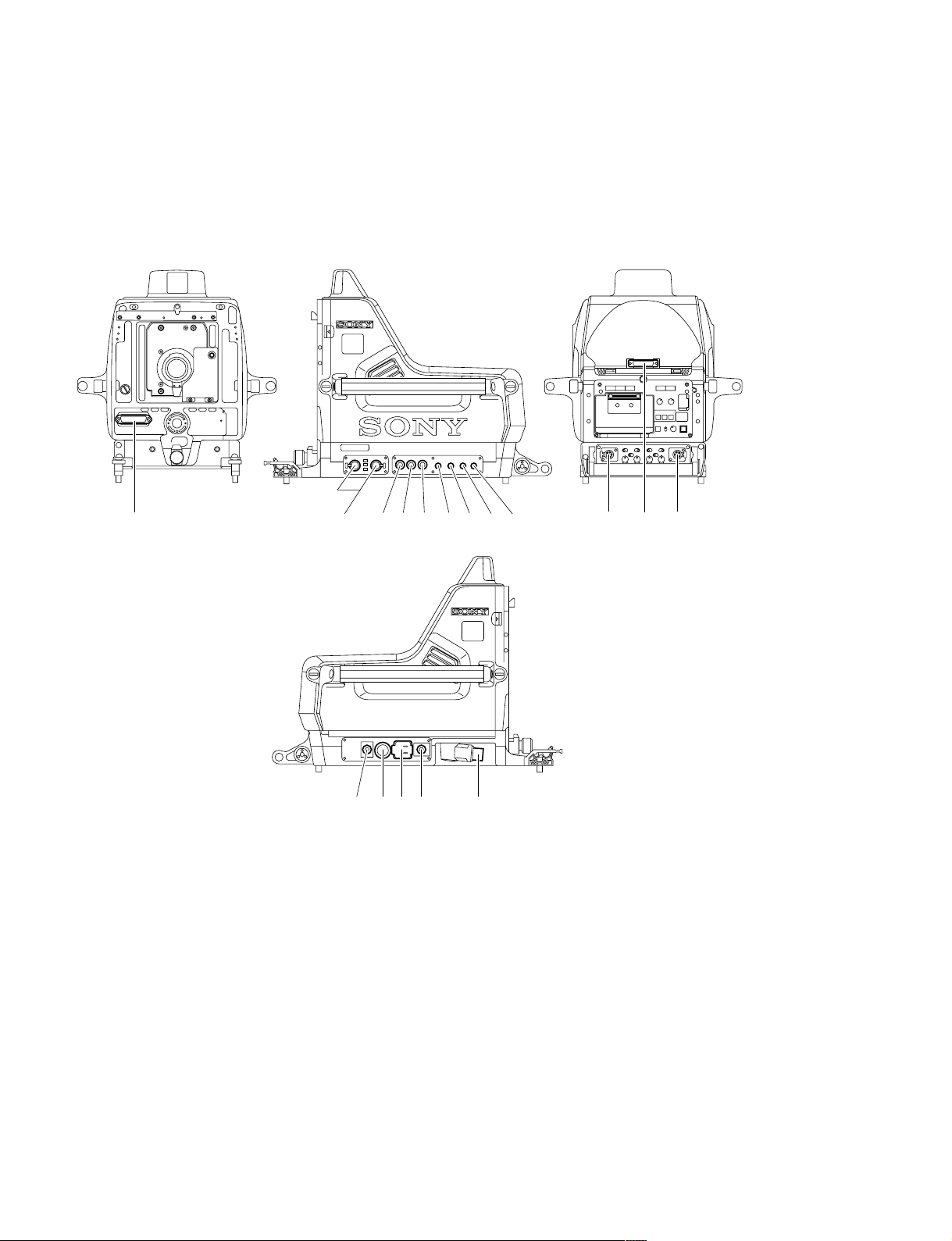
1-2-1. Connector Input/Output Signals
HDC-900/910 Connector Layout
1
1
1
!\ !/ 6 4 3 9 !, 7 8
1
5!] 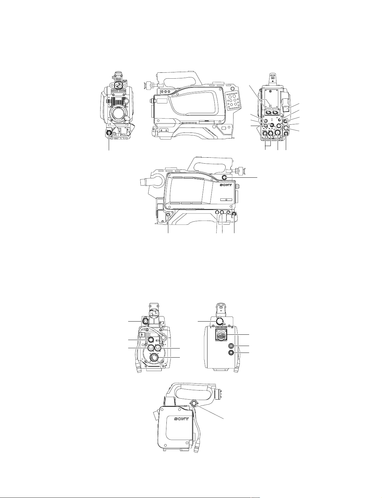
HDC-950/930 Connector Layout
!.
1-2. Connectors and Cables
!-
1
2
*
4
!,
7
9
!'
![
!/
!] 5
!;
8
* : Use 4 connector by selecting PROMPTER OUT, GENLOCK IN and RET IN signals with the switch.
PROMPTER OUT signal become effective when the camera is connected to CCU.
GENLOCK IN and RET IN signals become effective when the camera is used alone.
36!\
HKC-T950 Connector Layout
@-
@[
@-
@=
@=
@\
@]
@/
!\
HDC-900/950 IMM
@[
1-3 (E)

1-2. Connectors and Cables
Input/Output Signals
11
1 CCU connector
11
Based upon BTA S-004A/005A/006A 1.485 Gbps
serial
Output Signals
22
2 EARPHONE OUT (HDC-950/930)
22
EARPHONE mini jack
33
3 TEST OUT
33
BNC type 75 Z, 1.0 V p-p
**
*
44
4 PROMPTER OUT
44
**
BNC type 75 Z, 1.0 V p-p
55
5 HD SERIAL DIGITAL OUT
55
Based upon BTA-S004A
BNC type 75 Z, 0.8 V p-p 1.485 Gbps
@/@/
@/ VIDEO OUT (HKC-T950)
@/@/
BNC type 75 Z, 1.0 V p-p
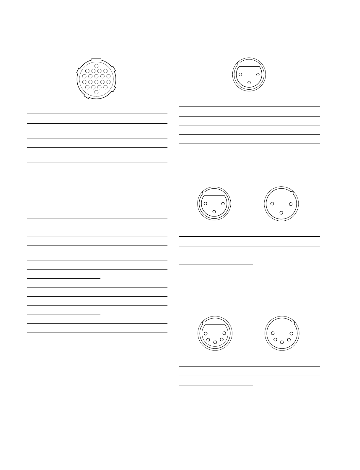
77
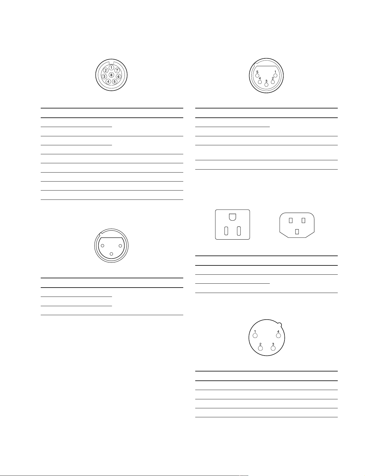
7 RET CONTROL (6P FEMALE)
77
(External view)
No. Signal I/O Specifications
1 INCOM 1 IN Zi > 10 kZ
MIC ON/OFF ON : GND
OFF : OPEN
2 INCOM 2 IN Zi > 10 kZ
MIC ON/OFF ON : GND
OFF : OPEN
3 GND ——
4 NC No connection
5 RET 1 ON/OFF IN Zi > 10 kZ
ON : GND
OFF : OPEN
6 RET 2 ON/OFF IN Zi > 10 kZ
ON : GND
OFF : OPEN
Input Signals
**
*
44
4 GENLOCK IN
44
**
(HDC-950/930)
BNC type 75 Z, 1.0 V p-p
**
*
44
4 RET IN
44
**
(HDC-950/930)
BNC type 75 Z, 1.0 V p-p
66
6 Not used
66
* : Use this connector by selecting PROMPTER OUT, GENLOCK IN and
RET IN signals with the switch on the rear panel of HDC-950/930.
PROMPTER OUT signal become effective when the camera is
connected to CCU.
GENLOCK IN and RET IN signals become effective when the camera is
used alone.
88
8 DC OUT (4P FEMALE)
88
1
4
23
(External view)
No. Signal I/O Specifications
1 GND —— GND for POWER
2 NC No connection
3 NC No connection
4 UNREG OUT +12 V dc 500 mA (max)
1-4 (E)
HDC-900/950 IMM
1-2. Connectors and Cables
99
9 REMOTE (8P FEMALE)
99
(External view)
No. Signal I/O Specifications
1 TX (+) HDC SERIAL DATA
2 TX (_)
3 RX (+) HDCU/MSU/RCP/CNU/VCS
4 RX (_) SERIAL DATA
5 TX GND —— GND for TX
6 POWER (+) OUT +26 V, 200 mA (max)
7 POWER GND —— GND for POWER (+)
8 VIDEO (X) 75 Z, 1.0 V p-p
CHASSIS GND —— CHASSIS GND
!/!/
!/ AUDIO IN CH1/CH2 (3P FEMALE)
!/!/
!-!-
!- INTERCOM CH1/CH2 (5P FEMALE)
!-!-
(External view)
No. Signal I/O Specifications
1 INCOM MIC (Y) IN _20 dBu (CARBON MIC)
2 INCOM MIC (X) IN _60 dBu (DYNAMIC MIC)
3
GND (INCOM/PGM)
4 INCOM OUT 0 dBu
RECEIVE
5 PGM OUT 0 dBu
——
(0 dBu = 0.775 Vrms)
!=!=
!= AC OUT (HDC-900/910)
!=!=
E
HDC-900/910 (CE) only
N
L
21
3
(External view)
No. Signal I/O Specifications
1 AUDIO (G) —— _60 dBu, _50 dBu, _40 dBu,
2 AUDIO (X) IN _30 dBu, _20 dBu, selectable
3 AUDIO (Y) IN High impedance, Balanced
(0 dBu = 0.775 Vrms)
L
No. Signal I/O Specifications
E GND —— CHASSIS GND
N UTL (C) OUT AC 100 V, 200 V or below
L UTL (H) OUT
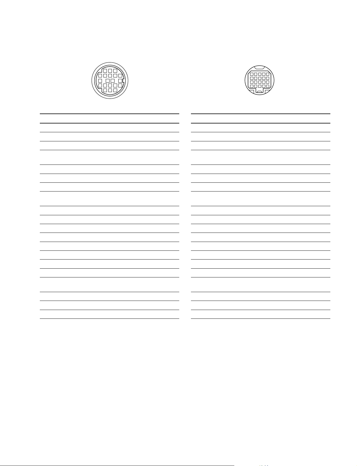
1-2. Connectors and Cables
!]!]
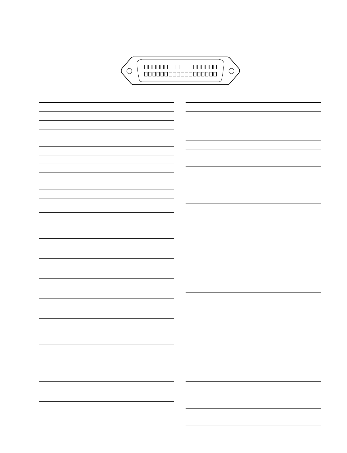
!] VTR (26P MALE) (HDC-900/910)
!]!]
B
6
5
A
4
11
3
10
2
1
7
12
17
9
16
8
15
22
14
21
13
20
19
24
18
23
(External view)
No. Signal I/O Specifications
A NC No connection
B VTR CMD GND —— GND for VTR CMD
1 GENLOCK IN Sync 0.6 V p-p, 0 V dc,
Zi = 75 Z
2 GENLOCK GND —— GND for GENLOCK
3 G/Y GND —— GND for G/Y
4 G/Y OUT 1 Vp-p, 0 V dc, Zo = 75 Z
5 R/PR OUT 1 Vp-p/±0.35 V p-p, 0 V dc,
Zo = 75 Z
6 R/PR GND —— GND for R/PR
7 B/PB OUT 1 Vp-p/±0.35 V p-p, 0 V dc,
Zo = 75 Z
8 B/PB GND —— GND for B/PB
9 CH1 MIC (X) OUT _20 dBu, Low impedance,
10 CH1 MIC (Y) OUT Balanced
11 CH1/CH2 MIC GND —— GND for CH1/CH2 MIC
12 NC No connection
13 NC No connection
14 INCOM LINE IN/OUT 0.5 V p-p
15 CH2 MIC (X) OUT _20 dBu, Low impedance,
16 CH2 MIC (Y) OUT Balanced
17 NC No connection
18 RET VIDEO IN 1.0 V p-p, 0 V dc,
Zi = 75 Z
19 RET VIDEO GND —— GND for RET VIDEO
20 AUDIO IN _6 dBu, 750 Z/1 kHz
21 RX COMMAND (X) IN RS-422
22 RX COMMAND (Y) IN
23 TX COMMAND (X) OUT RS-422
24 TX COMMAND (Y) OUT
(0 dBu = 0.775 Vrms)
!]!]
!] VTR (26P MALE) (HDC-950/930)
!]!]
B
6
5
A
4
11
3
10
2
1
7
12
17
9
16
8
15
22
14
21
13
20
19
24
18
23
(External view)
No. Signal I/O Specifications
A VTR UNREG IN +10.5 to 17 V dc
B UNREG GND —— GND for UNREG
1 GENLOCK IN Sync 0.6 V p-p, 0 V dc,
Zi = 75 Z
2 GENLOCK GND —— GND for GENLOCK
3 G/Y GND —— GND for G/Y
4 G/Y OUT 1 V p-p, 0 Vdc, Zo = 75 Z
5 R/PR OUT 1 V p-p/±0.35 V p-p, 0 V dc,
Zo = 75 Z
6 R/PR GND —— GND for R/PR
7B/PB OUT 1 V p-p/±0.35 V p-p, 0 V dc,
Zo = 75 Z
8 B/PB GND —— GND for B/PB
9 CH1 MIC (X) OUT _20 dBu, Low impedance
10 CH1 MIC (Y) OUT Balanced
11 CH1/CH2 MIC GND —— GND for CH1/CH2 MIC
12 UNREG (+) SENSE IN
13 UNREG (_) SENSE IN
14 INCOM LINE IN/OUT 0.5 V p-p
15 CH2 MIC (X) OUT _20 dBu, Low impedance,
16 CH2 MIC (Y) OUT Balanced
17 NC No connection
18 RET VIDEO IN 1.0 V p-p, 0 V dc,
Zi = 75 Z
19 RET VIDEO GND —— GND for RET VIDEO
20 AUDIO IN _6 dBu, 750 Z/1 kHz
21 RX COMMAND (X) IN RS-422
22 RX COMMAND (Y) IN
23 TX COMMAND (X) OUT RS-422
24 TX COMMAND (Y) OUT
(0 dBu = 0.775 Vrms)
1-6 (E)
HDC-900/950 IMM
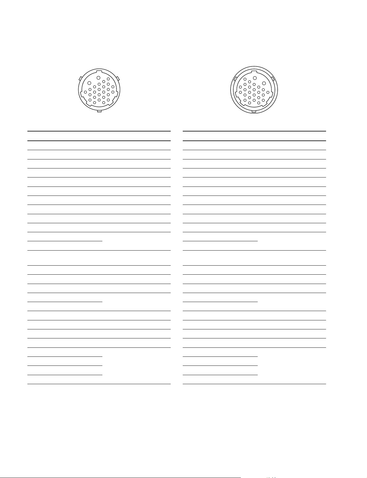
!\!\
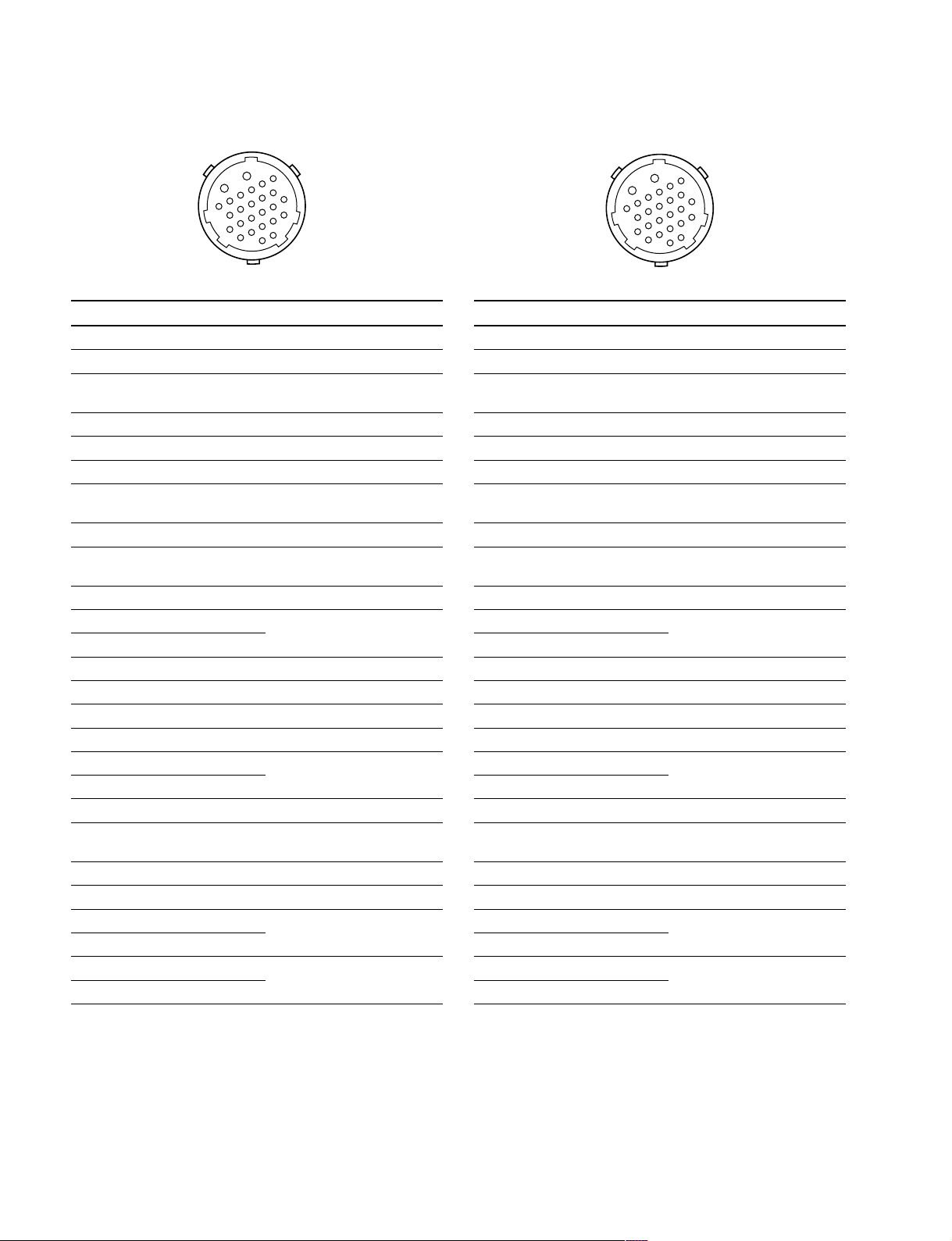
!\ LENS (36P FEMALE) (HDC-900/910)
!\!\
1-2. Connectors and Cables
18
36
No. Signal I/O Specifications
1 NC No connection
2 COMMON 5 V IN No connection
3 NC No connection
4 +12 V (LENS) OUT +12 V (at 2 A)
5 LENS DC GND —— GND for +12 V (LENS)
6 GND (SIG) —— GND
7 NC No connection
8 LENS EXT-1 IN
9 LENS EXT-2 IN
10 LENS EXT-3 IN
*
2
*
2
*
2
11 NC LENS AUX OUT ON : GND
OFF : High impedance
12 IRIS POSI IN Zi > 10 kZ
2 to 7 V
“3.4 ± 0.1 V (F16)”
“6.2 ± 0.1 V (F2.8)”
13 ZOOM POSI IN Zi > 10 kZ
2 to 7 V
“2 V (WIDE), 7 V (TELE)”
14 RET 1 ON IN Zi > 10 kZ
ON : GND
OFF : High impedance
15 RET 2 ON IN Zi > 10 kZ
ON : GND
OFF : High impedance
16 FOCUS POSI IN Zi > 10 kZ
2 to 7 V
“2 V (MIN), 7 V (∞)”
17 IRIS CONT SIG OUT 2 to 7 V
“3.4 ±0.1 V (F16)”
“6.2 ±0.1 V (F2.8)”
Zo < 1 kZ
18 IRIS AUTO OUT AUTO : GND
/MANU MANU : High impedance
Zo < 1 kZ
19 NC No connection
20 NC No connection
21 LENS R TALLY OUT ON : GND
OFF : High impedance
Zo < 1 kZ
22 EXP POSITION IN Zi > 10 kZ
1 to 4 V
1 V : _7.5d
4 V : +7.5d
(External view)
No. Signal I/O Specifications
23 RET 3 ON IN Zi > 10 kZ
24 LENS ADRS 0 IN
25 LENS ADRS 1 IN
26 LENS ADRS 2 IN
27 LENS ADRS 3 IN
28 EXTENDER 1 OUT ON : GND
29 EXTENDER 2 OUT ON : GND
30 F DEM (FAR) IN No connection
31 INCOM 1 IN Zi > 10 kZ
32 INCOM 2 IN Zi > 10 kZ
33 INCOM MIC 1 IN Zi > 10 kZ
34 INCOM MIC 2 IN Zi > 10 kZ
35 F CONT SIG OUT No connection
36 F DEM (NEAR) IN No connection
*
1 Zi > 10 kZ
*
2Zi > 10 kZ
EX1 EX2 EX3 MODE
1 1 1 EXTENDER OFF
1 0 1 EXT-1 (x 1.5) ON
0 1 1 EXT-2 (x 2) ON
0 0 1 EXT-3 (x 2.5) ON
1
19
ON : GND
OFF : High impedance
*
1
*
1
*
1
*
1
ON OFF : High impedance
ON OFF : High impedance
ENG/PRD ENG : GND
PRD : High impedance
ENG/PROD ENG : GND
PRD : High impedance
ON ON : GND
OFF : High impedance
ON ON : GND
OFF : High impedance
1 : High impedance
+0.5
0 : 0
V
_0
LENS ADRS 0 (low-order bit)
LENS ADRS 3 (high-order bit )
1 : High impedance
0 : 0 ±0.5 V
HDC-900/950 IMM
1-7 (E)
1-2. Connectors and Cables
!\!\
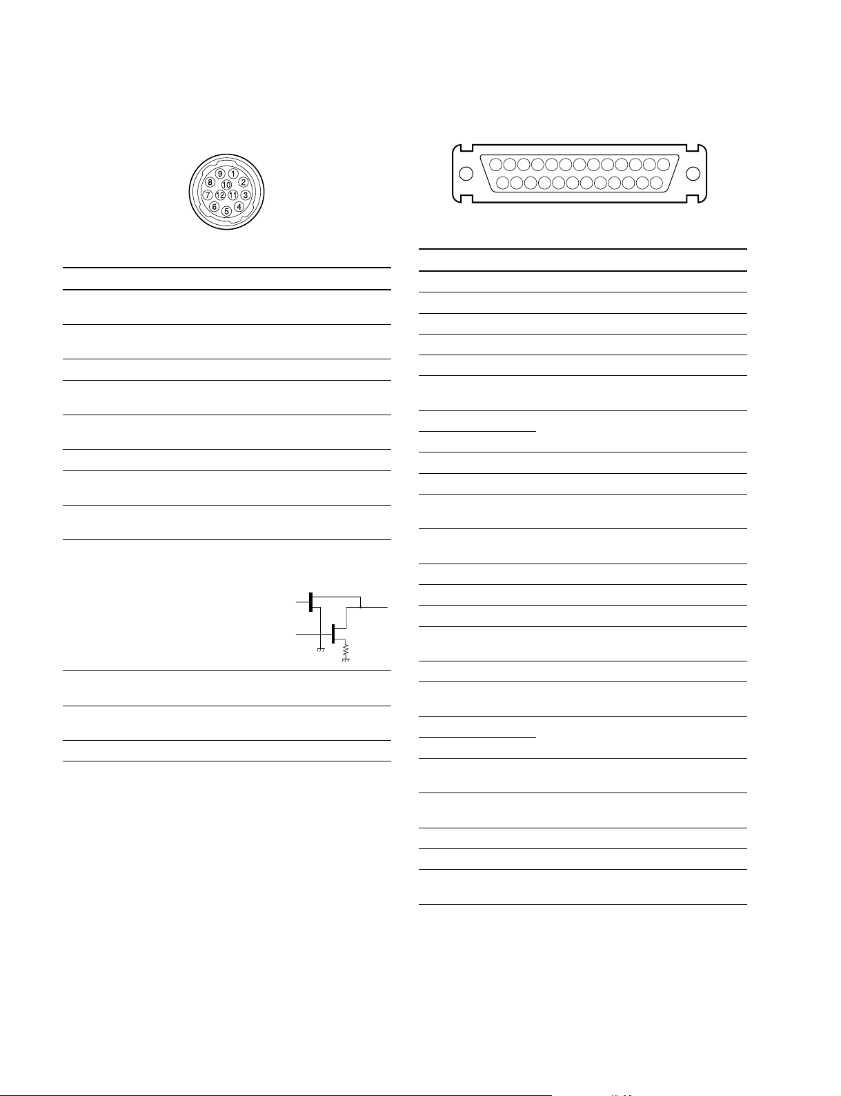
!\ LENS (12P FEMALE)
!\!\
(HDC-950/930, HKC-T950)
(External view)
No. Signal I/O Specifications
1 RET VIDEO IN ENABLE : 0 V
ENABLE DISABLE : +5 V or OPEN
2 VTR START IN ENABLE : 0 V
/STOP DISABLE : +5 V or OPEN
3 GND —— GND for UNREG
4 AUTO SERVO OUT AUTO : +5 V
5 IRIS CONT OUT +3.4 V (F16) to
6 UNREG OUT +10.5 V to +17 V
7 IRIS POSITION IN +3.4 V (F16) to
8 AUTO/MANU OUT AUTO IRIS : 0 V
9 EXTENDER IN EX 2 ON : GND
ON/OFF EX 0.8 ON : 30 kZ to GND
10 ZOOM IN WIDE : 2 V
POSITION TELE : 7 V
11 FOCUS POSI IN ∞ : 7 V
(/LENS RX) min. : 2 V
12 (LENS TX) OUT
MANU : 0 V or OPEN
+6.2 V (F2.8)
+6.2 V (F2.8)
MANUAL IRIS : +5 V
OFF : OPEN
EX 2 ON
EX 0.8 ON
30 kΩ
!;!;
!; VF (25P FEMALE) (HDC-900/910)
!;!;
13 123456789101112
25
(External view)
No. Signal I/O Specifications
1 Y VIDEO (X) OUT 1.0 V p-p, Zo = 75 Z
2PR VIDEO GND —— GND for PR VIDEO
3PR VIDEO (X) OUT 0.7 V p-p, Zo = 75 Z
4PB VIDEO GND —— GND for PB VIDEO
5PB VIDEO (X) OUT 0.7 V p-p, Zo = 75 Z
6 PEAKING IN 0 to 5 V dc
LEVEL
7 +12 V OUT +10.5 to +20 V
8 +12 V
9 NC No connection
10 S-DATA IN/OUT TTL level
11 R TALLY OUT ON : +5 V
12 EFFECT OUT ON : +5 V
13 NC No connection
14 Y VIDEO GND —— GND for Y VIDEO
15 S-CK OUT TTL level
16 BATT IND OUT ON : +5 V
17 CHASSIS GND ——
18 G TALLY OUT ON : +5 V
19 GND (+12 V) —— GND for +12 V
20 GND (+12 V)
21 VF-SEL IN BW : 0 V
22 H EXPAND OUT ON : GND
23 NC No connection
24 NC No connection
25 V EXPAND OUT ON : GND
1415161718192021222324
OFF : 0 V
OFF : 0 V
OFF : 0 V
OFF : 0 V
COLOR : +5 V
OFF : +5 V
OFF : +5 V
1-8 (E)
HDC-900/950 IMM

1-2. Connectors and Cables
!;!;
!; VF (20P FEMALE) (HDC-950/930)
!;!;
(External view)
No. Signal I/O Specifications
1 S-DA TA IN/OUT TTL level
2 NC No connection
3 NC No connection
4 SCK OUT TTL level
5 NC No connection
6 NC No connection
7 NC No connection
8 G TALLY OUT ON : 5 V
OFF : GND
9 NC No connection
10 NC No connection
11 NC No connection
12 Y VIDEO OUT 1.0 V p-p, Zo = 75 Z
13 VIDEO GND —— GND for VIDEO
14 Pb VIDEO OUT ±0.35 V p-p, Zo = 75 Z
15 Pr VIDEO OUT ±0.35 V p-p, Zo = 75 Z
16 NC No connection
17 R TALLY OUT ON : 5 V
OFF : GND
18 NC No connection
19 UNREG GND —— GND for UNREG
20 UNREG OUT +10.5 V to +17 V
!'!'
!' EXT I/O (20P) (HDC-950/930)
!'!'
11
5
17
18
19
20
1
2
3
4
10
16
(External view)
No. Signal I/O Specifications
1 Y VIDEO (X) OUT 1.0 V p-p, Zo = 75 Z
2 Y VIDEO (G) —— GND for Y VIDEO
3 PROMPTER (X) OUT 1.0 V p-p, Zo = 75 Z
4 PROMPTER (G) —— GND for PROMPTER
5 Pr VIDEO (X) OUT ±0.35 V p-p, Zo = 75 Z
6 Pr VIDEO (G) —— GND for Pr VIDEO
7 Pb VIDEO (X) OUT ±0.35 V p-p, Zo = 75 Z
8 Pb VIDEO (G) —— GND for Pb VIDEO
9 SDA VF IN/OUT TTL level
10 VD OUT Negative Pulse,
3.0 V p-p, Low impedance
11 CALL ON IN ON : L (0 v)
OFF : H (+3 V)
12 VF POWER OFF OUT ON : H (+5 V)
OFF : L (0 V)
13 MAIN POWER OUT ON : +8 V
ON/OFF OFF : GND
14 SCL VF OUT TTL level
15 TALLY GND —— GND for TALLY
16 BACK TALLY OUT ON : 5 V
OFF : GND
17 PANEL DATA IN RX SERIAL DATA
18 PANEL DATA OUT TX SERIAL DATA
19 VF UNREG + OUT
+12 V (+10.5 V to +17.0 V)
20 GND —— GND for UNREG
HDC-900/950 IMM
1-9 (E)
1-2. Connectors and Cables
!,!,
!, TRACKER (FEMALE)
!,!,
1
2
6
11
16
5
3
4
7
8139
12
10
14
15
17
182019
(External view)
No. Signal I/O Specifications
1 TRK R (X) OUT TRACKER RECEIVE
0 dBu unbalanced
2 TRK R (G) —— GND for TRACKER R
3 GND —— GND for UNREG/TALLY
(UNREG/TALLY)
4 R TALLY OUT ON : 5 V (Open Collector)
OFF : 0 V (Open Collector)
5 TRK PGM (G) —— GND for PGM
6 UNREG OUT +12 V (+10.5 to +17.0 V)
7 TRK T (X) IN TRACKER TALK
8 TRK T (Y) IN 0 dBu /_20 dBu
High impedance balanced
9 TRK T (G) —— GND for TRACKER T
10 TRK PGM (X) OUT _20 dBu unbalanced
11 NC No connection
12 G TALLY OUT ON : 5 V (Open Collector)
OFF : 0 V (Open Collector)
13 NC No connection
14 RX_DATA (0) IN TRUNK DATA IN, RS232-C
15 RX_DATA (1) IN
16 NC No connection
17 NC No connection
18 TX_DATA (0) OUT
TRUNK DATA OUT, RS232-C
19 TX_DATA (1) OUT
20 GND ——
(0 dBu = 0.775 Vrms)
!.!.
!. FRONT MIC (3P FEMALE) (HDC-950/930)
!.!.
21
3
(External view)
No. Signal I/O Specifications
1 CHU MIC (G) —— _60 dBu, _50 dBu, _40 dBu,
2 CHU MIC (X) IN _30 dBu, _20 dBu, selectable
3 CHU MIC (Y) IN High impedance, Balanced
(0 dBu = 0.755 Vrms)
@-@-
@- MIC (HKC-T950)
@-@-
(3P FEMALE) (3P MALE)
21
3
1
(External view) (External view)
No. Signal I/O Specifications
1 AUDIO (G) —— _60 dBu, _50 dBu, _40 dBu,
2 AUDIO (X) IN _30 dBu, _20 dBu, selectable
3 AUDIO (Y) IN High impedance, Balanced
2
3
(0 dBu = 0.755 Vrms)
@=@=
@= INCOM (HKC-T950)
@=@=
(5P FEMALE) (5P MALE)
5
1
2
4
3
1
5
4
2
3
1-10 (E)
(External view) (External view)
No. Signal I/O Specifications
1 INCOM MIC (Y) IN _20 dBu (CARBON MIC)
2 INCOM MIC (X) IN _60 dBu (DYNAMIC MIC)
3 GND (INCOMPGM) ——
4 INCOM RECEIVE OUT 0 dBu
5 PGM OUT 0 dBu
(0 dBu = 0.755 Vrms)
HDC-900/950 IMM
@[@[
@[ VF (HKC-T950)
@[@[
(20P FEMALE)
1-2. Connectors and Cables
(20P FEMALE)
123
12 11 10 9
17 16 15
45678
141813
20
19
(External view)
No. Signal I/O Specifications
1 S DATA IN/OUT TTL level
2 NC No connection
3 NC No connection
4 SCK OUT TTL level
MANU : 0 V or OPEN
5 NC No connection
6 NC No connection
7 NC No connection
8 G TALLY OUT ON : 5 V
OFF : GND
9 NC No connection
10 NC No connection
11 NC No connection
12 Y VIDEO OUT 1.0 V p-p, Zo = 75 Z
13 VIDEO GND —— GND for VIDEO
14 NC No connection
15 NC No connection
16 NC No connection
17 R TALLY OUT ON : 5 V
OFF : GND
18 NC No connection
19 UNREG GND —— GND for UNREG
20 UNREG OUT +10.5 V to +1.7 V
12345
678910
11 12 13 14 15
16 17 18 19 20
(External view)
No. Signal I/O Specifications
1 S DATA IN/OUT TTL level
2 NC No connection
3 NC No connection
4 SCK IN TTL level
MANU : 0 V or OPEN
5 NC No connection
6 NC No connection
7 NC No connection
8 G TALLY IN ON : 5 V
OFF : GND
9 NC No connection
10 NC No connection
11 NC No connection
12 Y VIDEO IN 1.0 V p-p, Zi = 75 Z
13 VIDEO GND —— GND for VIDEO
14 NC No connection
15 NC No connection
16 NC No connection
17 R TALLY IN ON : 5 V
OFF : GND
18 NC No connection
19 NC No connection
20 NC No connection
HDC-900/950 IMM
1-11 (E)
1-2. Connectors and Cables
@]@]
@] CAM BODY (HKC-T950)
@]@]
(26P MALE)
B
6
5
A
4
11
3
2
1
8
7
13
12
18
(External view)
No. Signal I/O Specifications
A UNREG IN 13 V to 17 V
B UNREG GND —— GND for UNREG
1 OHB H OUT 0.3 V p-p Positive pulse
2 OHB H (G) —— GND for OHB H
3 G VIDEO (G) —— GND for G VIDEO
4 G VIDEO (X) OUT
5 R VIDEO (X) OUT
6 R VIDEO (G) —— GND for R VIDEO
7 B VIDEO (X) OUT 95 mV p-p, Zo = 75 Z (100 %)
8 B VIDEO (G) —— GND for B VIDEO
9 MIC (X) OUT _60 dBu, _50 dBu, _40 dBu,
10 MIC (Y) OUT _30 dBu, _20 dBu, selectable
11 INCOM/MIC GND —— GND for INCOM/MIC,
12 IRIS CONT IN +3.4 V (F16) to +6.2 V (F2.8)
13 CHU F IN 0.3 V p-p Positive pulse
14 INCOM RECEIVE IN 0 dBu
15 INCOM MIC (X) OUT _20 dBu (CARBON MIC)
16 INCOM MIC (Y) OUT _60 dBu (DYNAMIC MIC)
17 CHU H IN 150 mV p-p Positive pulse
18 VF VIDEO (X) IN 180 mV p-p, Zi = 75 Z
19 VF VIDEO (G) —— GND for VF VIDEO,CHU H
20 PGM IN 0 dBu
21 RX COMMAND (X) IN
22 RX COMMAND (Y) IN 340 mV p-p
23 TX COMMAND (X) OUT
24 TX COMMAND (Y) OUT
17
10
16
9
22
15
14
21
20
19
24
23
300 mV p-p, Zo = 75 Z (100 %)
300 mV p-p, Zo = 75 Z (100 %)
CHU F, IRIS CONT
@\@\
@\ OPT HEAD (HKC-T950)
@\@\
(26P FEMALE)
B
6
5
11
17
16
22
21
24
(External view)
No. Signal I/O Specifications
A UNREG OUT 13 V to 17 V
B UNREG GND —— GND for UNREG
1 OHB H IN 0.3 V p-p Positive pulse
2 OHB H (G) —— GND for OHB H
3 G VIDEO (G) —— GND for G VIDEO
4 G VIDEO (X) IN 300 mV p-p, Zi = 75 Z (100 %)
5 R VIDEO (X) IN 300 mV p-p, Zi = 75 Z (100 %)
6 R VIDEO (G) —— GND for R VIDEO
7 B VIDEO (X) IN 95 mV p-p, Zi = 75 Z (100 %)
8 B VIDEO (G) —— GND for B VIDEO
9 MIC (X) IN _60 dBu, _50 dBu, _40 dBu,
10 MIC (Y) IN _30 dBu, _20 dBu, selectable
11 INCOM/MIC GND —— GND for INCOM/MIC,
12 IRIS CONT OUT +3.4 V (F16) to +6.2 V (F2.8)
13 CHU F OUT 0.3 V p-p Positive pulse
14 INCOM RECEIVE OUT 0 dBu
15 INCOM MIC (X) IN _20 dBu (CARBON MIC)
16 INCOM MIC (Y) IN _60 dBu (DYNAMIC MIC)
17 CHU H OUT 150 mV p-p Positive pulse
18 VF VIDEO (X) OUT 180 mV p-p, Zo = 75 Z
19 VF VIDEO (G) —— GND for VF VIDEO, CHU H
20 PGM OUT 0 dBu
21 RX COMMAND (X) OUT
22 RX COMMAND (Y) OUT 340 mV p-p
23 TX COMMAND (X) IN
24 TX COMMAND (Y) IN
A
4
3
10
2
9
15
20
23
1
8
7
14
13
12
19
18
CHU F, IRIS CONT
1-12 (E)
HDC-900/950 IMM
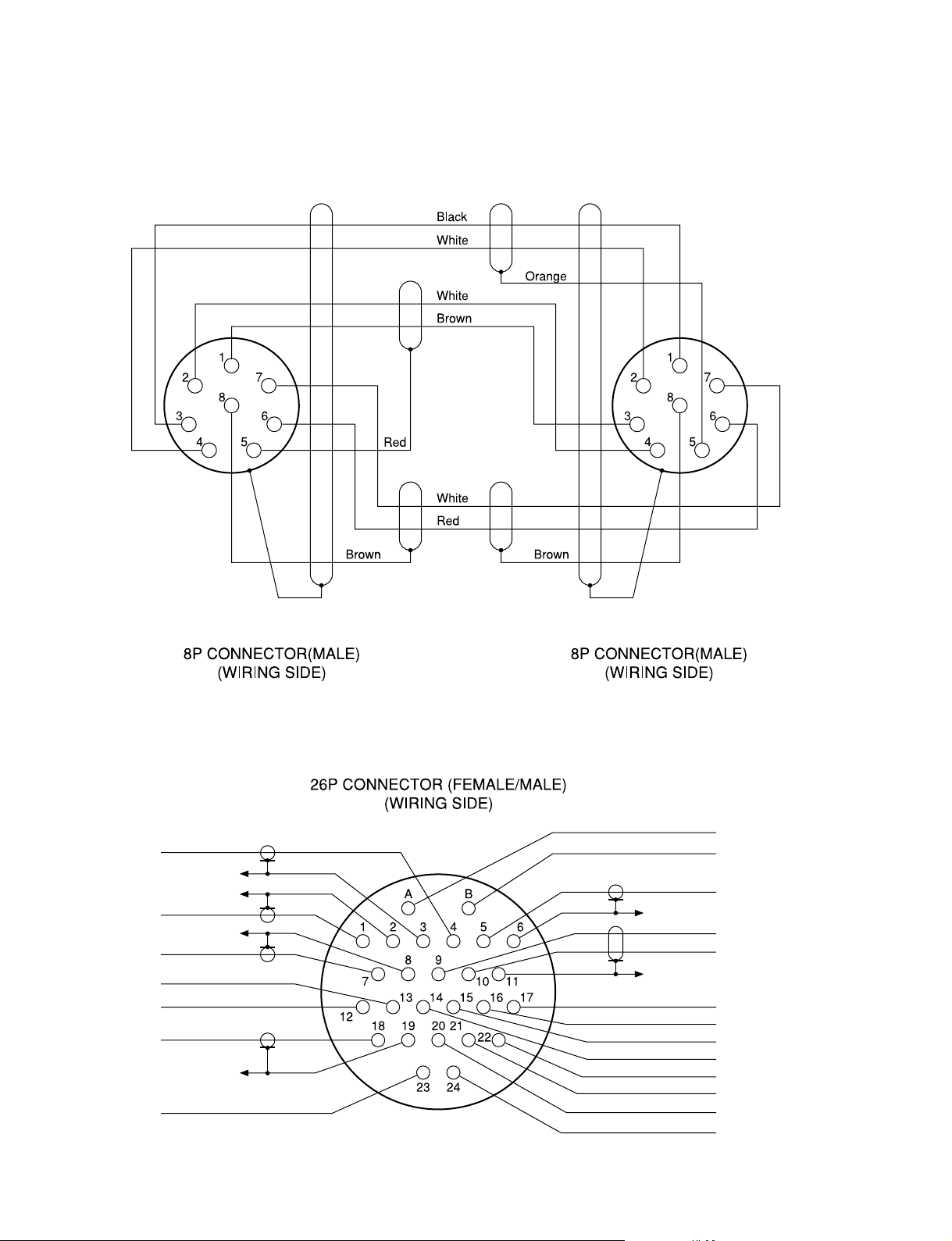
1-2-2. Wiring Diagrams for Cables
CCA-5 Cable
1-2. Connectors and Cables
HDCZ Cable
Yellow
Black
Blue
Red
Brown
Gray
Red
Black
White
Red
Red
White
Blue
Red
White
Orange
White
Red
Yellow
White
HDC-900/950 IMM
1-13 (E)

1-2. Connectors and Cables
1-2-3. Connection Connectors/Cables
Connection made with the connector panels during installation or service, should be made with the connectors/
complete cable assemblies specified in the following list,
or equivalent parts.
Indication Connection connector/cable
TEST OUT 1-569-370-12 Plug, BNC
PROMPTER
SERIAL OUT
VIDEO OUT
(BNC)
AUDIO IN 1-508-084-00 XLR, 3P Male or
MIC IN ITT Cannon XLR-3-12C equivalent
(3P FEMALE) Cable assembly
MIC IN 1-508-083-00 XLR, 3P, Female or
(3P MALE) ITT Cannon XLR-3-11C equivalent
RET CONTROL 1-560-078-00 Plug, 6P Male or
(6P FEMALE) HIROSE HR10-7PA-6P equivalent
DC OUT 1-566-425-11 Plug, 4P Male or
(4P FEMALE) HIROSE HR10A-7P-4P equivalent
INTERCOM 1-508-370-11 XLR, 5P Male or
INCOM ITT Cannon XLR-5-12C equivalent
(5P FEMALE) Cable assembly
INCOM 1-508-363-00 XLR, 5P Female or
(5P MALE) ITT Cannon XLR-5-11C equivalent
VTR 1-564-184-00 Plug, 26P Female or
CAM BODY Cable assembly
OPT HEAD 1-564-183-31 Plug, 26P Male or
(26P FEMALE) Cable assembly
DC IN 1-508-362-00 XLR, 4P Female or
(4P MALE) ITT Cannon XLR-4-11C equivalent, or
(supplied with HKC-T950, 0.8 m)
1-823-599-11
Cable assembly
(supplied with HKC-T950, 0.8 m)
1-823-599-11
(supplied with HKC-T950, 0.8 m)
1-823-600-11
Cable assembly
(supplied with HKC-T950, 0.8 m)
1-823-600-11
HDCZ-A10
(supplied with HKC-T950, 10 m)
1-823-615-11
HDCZ-A25 (option, 25 m)
1-823-616-11
HDCZ-A50 (option, 50 m)
1-823-617-11
HDCZ-A10
(supplied with HKC-T950, 10 m)
1-823-615-11
HDCZ-A25 (option, 25 m)
1-823-616-11
HDCZ-A50 (option, 50 m)
1-823-617-11
Cable assembly 1-551-577-00
(Supplied with AC-550/550CE)
*3
*3
*3
*3
*3
*3
Indication Connection connector/cable
REMOTE 1-766-848-11 Plug, 8P Male or
(8P FEMALE) CCA-5 cable assembly (option)
CCA-5-10 (10 m) /CCA-5-3 (3 m) or
REMOTE cable 1-783-372-11
(supplied with RM-B150, 10 m)
TRACKER HIROSE HR25-9P-20P equivalent
(20P FEMALE)
VF Cable assembly
(20P FEMALE) (supplied with HKC-T950, 0.7 m)
1-792-603-21
*1: Use of REMOTE cable enables to monitor video signals.
*2: If using a cable of length different from a standard product, contact your
local Sony Sales Office/Service Center.
*3: Only for HKC-T950.
*2
*1 *2
1-2-4. Note in connecting CCU connector
It is recommendable to clean the optical contact portions
mentioned below before connecting this unit to the camera
control unit.
. CCU connector of this unit
. Camera connector of the camera control unit
. Optical/Electrical cable
It is also necessary to clean the optical contact portions
mentioned below before using the HDC-950/930 to the
large lens adaptor CA-905L.
. CA cable of a large lens adaptor
. CCU connector of a large lens adaptor
For details on a cleaning method, refer to Section 2-1
“Cleaning of Connector/Cable”.
1-14 (E)
HDC-900/950 IMM
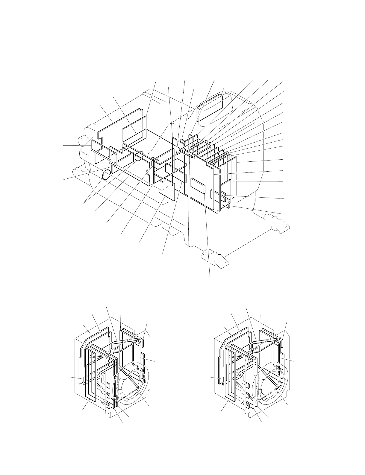
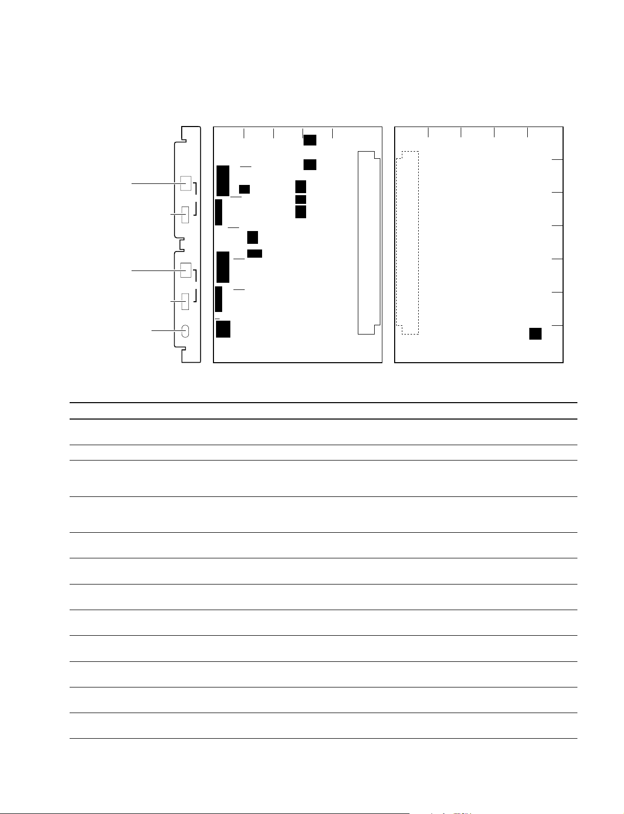
1-3. Location of Printed Circuit Boards
HDC-900/910
1-3. Location of Printed Circuit Boards
CN-2073
SW-1019
CN-1702
CN-1974
SW-1020
CN-2016
PS-582
CN-1956
RX-28
AT-131
MB-883
CN-986
RE-184
RE-182
LE-172
RE-181
DU-104
AU-271
AT-130
SG-268
DAP-24
DAD-37
VDA-55
DPR-156
DPR-154
VA-196
SDI-49
IF-784
SW-1045
CN-2074
CN-1961
RP-114
DU-69
TG-214
BI-145
DR-412
SERVO DRIVER
NR-69/73
PA-239
CN-2015
CN-1947
BI-145
CN-1998
CN-1961
CN-2017
RP-114
DU-69
TG-214
BI-150
DR-492
SERVO DRIVER
CN-2329
BI-150
NR-73
PA-239
HDC-900/950 IMM
HDC-900 HDC-910
1-15 (E)
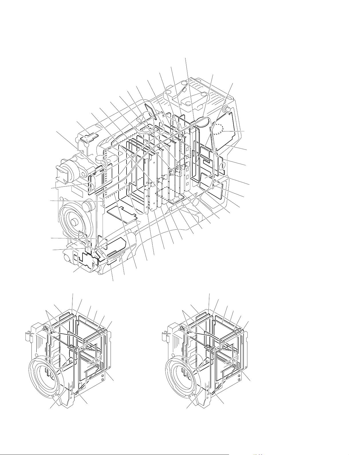
1-3. Location of Printed Circuit Boards
HDC-950/930
DPR-156
CN-2018
SW-1018
CN-1954
CN-1953
LP-113
RE-188
CN-1952
DU-104
RE-182
RE-184
CN-1702B
CN-2094
SW-1016
MB-882
CN-2026
SW-1029
BI-145
RX-28
DU-69
SW-1013
PA-239
NR-69/73
TG-214
SW-1015
RP-114
DR-412
SERVO DRIVER
SDI-49
SW-1014
VA-196
CN-1964
VDA-55
DPR-154
BI-150
DAP-24
DAD-37
DU-69
AT-130
SG-268
PA-239
AU-271
NR-69/73
TG-214
CN-1702B
SW-1017
SW-1027
CN-1951
CN-2063
CN-1955
RE-181
RP-114
DR-492
SERVO DRIVER
1-16 (E)
BI-145
HDC-950
CN-1947
CN-1961
BI-150
CN-1961
CN-2329
HDC-930
HDC-900/950 IMM
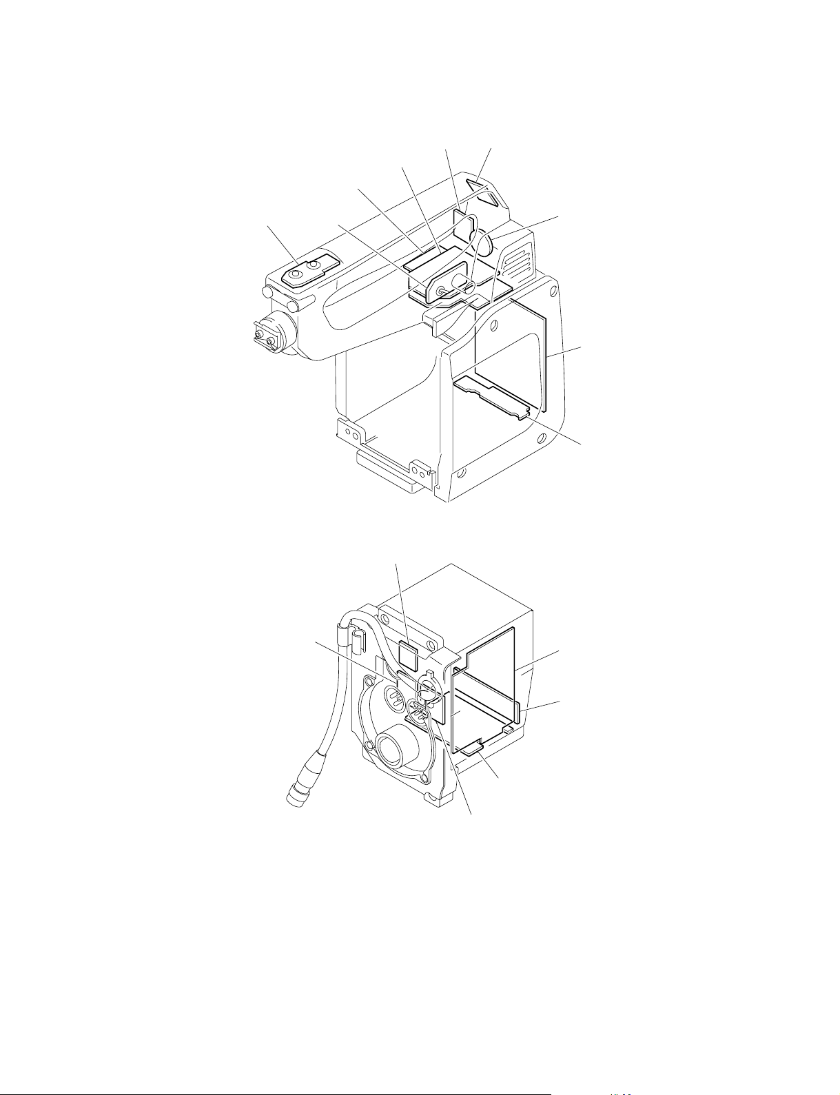
HKC-T950
1-3. Location of Printed Circuit Boards
LE-256CN-2270
AT-146
IF-845
SW-1065 SW-1066
CN-2271
RE-202
CN-2202
SW-1076
CN-2264
AT-147
CN-2203
IF-846
CN-2265
HDC-900/950 IMM
1-17 (E)
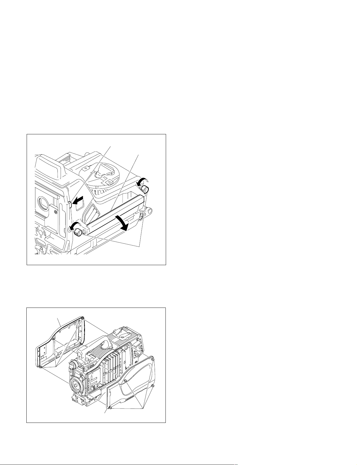
1-4. Opening/Closing the Side Panel
1-4. Opening/Closing the Side Panel
HDC-900/910
1. Unscrew the two lock screws of the side panel.
2. While sliding the safety lock toward the lens, open the
side panel by holding the handle.
3. Close the side panel and tighten securely the lock
screws of the side panel.
[Reference][Reference]
[Reference]
[Reference][Reference]
Closing the side panel brings the safety lock to an
automatic locking.
Safety lock
Handle
Lock screw of the
side panel
HDC-950/930
1. Unscrew the eight screws as shown in the figure, then
remove the inside panel and outside panel.
2. Reinstall in the reverse order of removal step 1.
Outside panel
Screws
Inside panel
Screws
1-18 (E)
HDC-900/950 IMM
S104
S103
S1
S101
AU-271 board (A side)
S102
S201
S2
S202
S301
S304
S203
S204
S303
B
C
D
E
F
G
A
54 3 2 1
AU
CM
DYN
INCOM 1
INCOM 1 switch
INCOM 1 MIC GAIN switch
MIC GAIN
DYN
INCOM 2
MIC GAIN
MIC
MONITOR
ON
+
0
_
+
0
_
OFF
INCOM 2 switch
INCOM 2 MIC GAIN switch
MIC MONITOR switch
AU-271 board suffix -13 and higher
(B side)
S300
1
A
B
C
D
E
F
G
2345
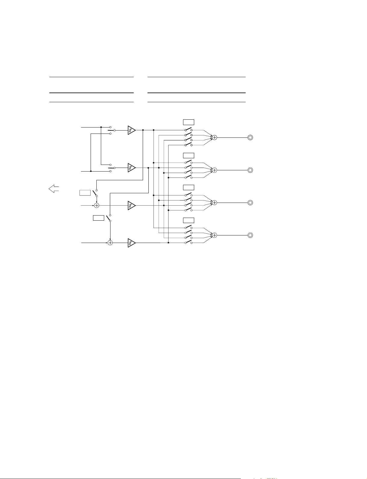
1-5. Switch Setting on the Boards
AU-271 board
1-5. Switch Setting on the Boards
Ref. No. Name Contents Factory Setting
S1-1
S1-2
S2-1
S2-2 PGM2 INCOM2 RECEIVE Switch ON to mix the PGM2 signal adjusted the sound volume OFF
S101-1 PGM1 MUTE ON/OFF Switch OFF to output the PGM1 signal to the PGM OUT of the OFF
S101-2 PGM2 MUTE ON/OFF Switch OFF to output the PGM2 signal to the PGM OUT of the ON
S101-3 INCOM1 MUTE ON/OFF Switch OFF to output the INCOM1 RECEIVE signal to the PGM OUT OFF
S101-4 INCOM2 MUTE ON/OFF Switch OFF to output the INCOM2 RECEIVE signal to the PGM OUT ON
S102-1 PGM1 MUTE ON/OFF Switch OFF to output the PGM1 signal to the INCOM OUT of OFF
S102-2 PGM2 MUTE ON/OFF Switch OFF to output the PGM2 signal to the INCOM OUT of ON
S102-3 INCOM1 MUTE ON/OFF Switch OFF to output the INCOM1 RECEIVE signal to the INCOM OFF
S102-4 INCOM2 MUTE ON/OFF Switch OFF to output the INCOM2 RECEIVE signal to the INCOM ON
HDC-900/950 IMM
*1
TRACKER INCOM2 ON/OFF Switch ON to mix the TRACKER TALK signal of the Tracker OFF
connector to CCU INCOM2 RECEIVE OUT.
*2
*2
Not used —— ——
PGM1 INCOM1 RECEIVE Switch ON to mix the PGM1 signal adjusted the sound volume by OFF
MIX ON/OFF the PGM volume control to the INCOM1 RECEIVE signal before
the sound volume adjustment.
MIX ON/OFF by the PGM volume control to the INCOM2 RECEIVE signal before
the sound volume adjustment.
INTERCOM1 connector.
INTERCOM1 connector.
of the INTERCOM1 connector.
of the INTERCOM1 connector.
the INTERCOM1 connector.
the INTERCOM1 connector.
OUT of the INTERCOM1 connector.
OUT of the INTERCOM1 connector.
1-19 (E)

1-5. Switch Setting on the Boards
Ref. No. Name Contents Factory Setting
S103 INCOM1 MIC GAIN +/0/_ Select the audio level of INTERCOM1/2 to be sent to CCU. 0
+ :+6dB
0 : 0dB
_ :_6dB
S104 INCOM1 MIC TYPE Select from two options below in accordance with the microphone CM
of the head set connected to the INTERCOM1/2 connector.
CM : Carbon microphone
DYN :Dynamic microphone
S201-1 PGM1 MUTE ON/OFF Switch OFF to output the PGM1 signal to the PGM OUT of the ON
INTERCOM2 connector.
S201-2 PGM2 MUTE ON/OFF Switch OFF to output the PGM2 signal to the PGM OUT of OFF
the INTERCOM2 connector.
S201-3 INCOM1 MUTE ON/OFF Switch OFF to output the INCOM1 RECEIVE signal to the PGM ON
OUT of the INTERCOM2 connector.
S201-4 INCOM2 MUTE ON/OFF Switch OFF to output the INCOM2 RECEIVE signal to the PGM OFF
OUT of the INTERCOM2 connector.
S202-1 PGM1 MUTE ON/OFF Switch OFF to output the PGM1 signal to the INCOM OUT of the ON
INTERCOM2 connector.
S202-2 PGM2 MUTE ON/OFF Switch OFF to output the PGM2 signal to the INCOM OUT of the OFF
INTERCOM2 connector.
S202-3 INCOM1 MUTE ON/OFF Switch OFF to output the INCOM1 RECEIVE signal to the INCOM ON
OUT of the INTERCOM2 connector.
S202-4 INCOM2 MUTE ON/OFF Switch OFF to output the INCOM2 RECEIVE signal to the INCOM OFF
OUT of the INTERCOM2 connector.
S203 INCOM2 MIC GAIN +/0/_ Select the audio level of the INTERCOM1/2 to be sent to CCU. 0
+ :+6dB
0 : 0dB
_ :_6dB
S204 INCOM2 MIC TYPE Select from two options below in accordance with the microphone of CM
the head set connected to the INTERCOM 1/2 connector.
CM : Carbon microphone
DYN :Dynamic microphone
*3
S300-1
AUDIO1 +12 V OFF/ON Switch ON to supply +12 V for MIC POWER to the microphone OFF
connected the AUDIO IN 1 connector.
*3
S300-2
AUDIO2 +12 V OFF/ON Switch ON to supply +12 V for MIC POWER to the microphone OFF
connected the AUDIO IN 2 connector.
S301-1 TRACKER RECEIVE OUT Switch ON to mix the PGM1 signal to the TRACKER RECEIVE OUT OFF
PGM1 MIX of the TRACKER connector.
S301-2 TRACKER RECEIVE OUT Switch ON to mix the PGM2 signal to the TRACKER RECEIVE OUT OFF
PGM2 MIX of the TRACKER connector.
*1
S301-3
TRACKER RECEIVE OUT Switch ON to mix the INCOM2 RECEIVED signal to the TRACKER OFF
IMCOM2 RECEIVE MIX RECEIVE OUT of the TRACKER connector.
*1
S301-4
TRACKER RECEIVE OUT Switch ON to mix the INCOM2 TALK signal to the TRACKER OFF
INCOM2 TALK MIX RECIVE OUT of the TRACKER connector.
S303 MIC MONITOR ON/OFF Switch ON to monitor the microphone input signal at the INCOM OUT OFF
or EARPHONE OUT.
S304 TRACKER (T) 0/_20 Select the input level of the TRACKER Connector. 0
0 : 0dBu
_20 : _20dBu
(0dBu = 0.775 Vrms)
1-20 (E)
HDC-900/950 IMM
1-5. Switch Setting on the Boards
*1: The Tracker connector communicates to INCOM1 at the standard setting, yet it is communicable to INCOM2 by setting S1-1, S301-1
and S301-4
to ON.
*2: When setting S2-1 or S2-2 to ON, set bit1 and bit2 of S101, S102, S201 and S202 as shown below to prevent PGM1 and PGM2
signals from being mixed double.
S2-1 S101, 102, 201, 202 S2-2 S101, 102, 201, 202
bit1 bit12
ON ON ON ON
INCOM1
PGM 1
PGM 2
PGM1/2 swiitch
(Panel)
INCOM2
PGM1/2 swiitch
(Panel)
bit1
bit2
bit3
bit4
bit1
bit2
bit3
bit4
S101
S102
PGM OUT
INCOM OUT
INTERECOM CH1
INTERECOM CH1
CCU
S2-1
INCOM1
S2-2
INCOM2
bit1
bit2
bit3
bit4
bit1
bit2
bit3
bit4
S201
S202
PGM OUT
INCOM OUT
INTERECOM CH2
INTERECOM CH2
n
Each bit of S101, S102, S103 and S104 is opened when it is set to “ON” position.
Set to “OFF”position to close the switch.
*3: AU-271 board suffix -13 and higher.
HDC-900/950 IMM
1-21 (E)
Loading...