


HCD-MD515
RM-MD515
SERVICE MANUAL
HCD-MD515 is the Amplifier, CD player, MD |
|
|
Deck and Tuner section and RM-MD515 is the |
RM-MD515 |
|
Detachable Controller section in DHC-MD515. |
||
|
US Model
AEP Model
UK Model
E Model
Tourist Model
HCD-MD515
U.S and foreign patents licensed from Dolby Laboratories Licensing Corporation.
|
Model Name Using Similar Mechanism |
NEW |
|
|
|
|
|
|
CD Mechanism Type |
CDM48-5BD29 |
|
CD |
|
|
|
Base Unit Name |
BU-5BD29 |
||
Section |
|||
Optical Pick-up Name |
KSS-213BA/F-NP |
||
|
|||
|
|
|
|
|
Model Name Using Similar Mechanism |
NEW |
|
MD |
|
|
|
MD Mechanism Type |
MDM-C1D |
||
Section |
|
|
|
Base Unit Name |
MBU-C1 |
||
|
|
|
|
|
Optical Pick-up Name |
KMS-260A/J1N |
|
|
|
|
SPECIFICATIONS
MINI Hi-Fi COMPONENT SYSTEM
MICROFILM
SELF DIAGNOSTICS
– 2 –
MD SECTION
1. OPERATING THE ERROR HISTORY MODE
All operations are performed using the MULTI JOG dial and PROGRAM button.
1.Enter the test mode for MD function. (*1)
2.Turn the MULTI JOG dial and display “ERR DP MODE”.
3.Press the ENTER/YES button, therefor enter the error history mode and change the display “total rec”.
4.Press the EDIT/NO button, therefor end the error history mode and change the display “ERR DP MODE”.
(*1) See the “SECTION 4 TEST MODE” (page 21) for detail of test mode.
2. OPERATING THE DISPLAYED HISTORYS
1.Turn the MULTI JOG dial and change the display of error history contents.
2.Press the PROGRAM button and display error history function.
3.Press the PROGRAM button again and back the display of error history contents.
Table 1.
Contents |
|
Function |
Display |
|||
|
|
|
|
|
|
|
total rec |
Total time of laser power high. |
r |
h |
|||
|
About 20% of total recording time. |
|
|
|||
total play |
Total time of playback. |
p |
h |
|||
|
|
|
|
|
|
|
retry error |
Total count of record and playback |
r |
p |
|||
|
retry error. |
|
|
|||
|
|
|
|
|
|
|
total error |
Total count of error. |
total |
||||
err history |
Error contents display of from |
0 E |
(*2) |
|||
|
latest one“00” to last ten “09”. |
|
|
|||
|
(Turn the |
MULTI JOG |
dial and |
|
|
|
|
change the error NO.) |
|
|
|||
|
|
|
|
|||
err refresh |
Press the |
PROGRAM |
button and |
complete |
||
(*3) |
clear the error histories memory |
|
|
|||
|
|
|
|
|
|
|
(*2) See table 1-1. for contents of each error code.
(*3) Error refresh with optical pick-up exchange, another not execute.
|
|
Table 1-1. |
|
|
|
|
|
Display |
|
Contents |
|
(error No./code) |
|||
|
|||
|
|
|
|
0: |
E00 |
No error |
|
|
|
|
|
0: |
E01 |
Disc error PTOC does not read |
|
|
|
|
|
0: |
E02 |
Disc error UTOC does not read |
|
0: |
E03 |
Loading error |
|
|
|
|
|
0: |
E04 |
Address does not read |
|
|
|
|
|
0: |
E05 |
Out of FOK |
|
0: |
E06 |
Focus does not work |
|
|
|
|
|
0: |
E07 |
Retry of record |
|
|
|
|
|
0: |
E08 |
Record retry error |
|
0: |
E09 |
Retry of Playback |
|
|
|
|
|
0: |
E0A |
Playback retry error |
|
|
|
|
|
CD SECTION
1. OPERATING THE DISPLAYED HISTORYS
1. Press the DIMMER button, DBFB button, and CD 16 button simultaneously and enter the test mode.
2.Press the PROGRAM button, and mechanical error count and the cout of “NO DISC” that optical system judged are displyed.
3.Under this condition press the buttons in Table 2, and the respective operations are executed as listed below.
Table 2.
Button |
Function |
MD/CD 1 Mechanical error cord from latest one to last ten are displayed each time this button is pressed. (*1)
MD/CD 2 The reasons of “NO DISC” from latest one to last ten are displayed each time this button is pressed. (*2)
CD 16 Reset the count of mechanical error.
CD 26 Reset the count of “NO DISC”.
(*1) Mechanical error code
M0*=******
(a)(b) (c) (d)
(a)The number of Mechanical error. Latest one “00” to last ten “09”
(Turn the MULTI JOG dial and change the error No.)
(b)“FF”: Mechanical error, when mechanical initialize to
completion.
Others: Mechanical error in the midst of mechanical initialize.
(c)“4 *”: Mechanical error in the midst of mechanical initial-
ize, when sub tray set into the stocker.
“5 *”: Mechanical error in the midst of mechanical initialize, when sub tray take out to the stocker.
(d) “2 *”: Mechanical error in the midst of elevator moving.
(*2) NO DISC error code
D0*=******
(a)(b) (c) (d)
(a)The number of NO DISC error. Latest one “00” to last ten “09”
(Turn the MULTI JOG dial and change the error No.)
(b)“01”: Focus error “02”: GFS error “03”: Set up error
(c)“00”: NO DISC error (Does not chucking retry) “02”: NO DISC error (Chucking retry to completion)
(d)The status, when judged NO DISC error. “3 *”: Stop
“4 *”: |
Set up |
“5 *”: |
TOC read |
“6 *”: |
Access |
“7 *”: |
Play |
“8 *”: |
Pause |
“9 *”: |
Manual search (Play) |
– 3 –

|
TABLE OF CONTENTS |
|
SELF DIAGNOSTICS ...................................................... |
2 |
|
1. |
SERVICING NOTES ............................................... |
4 |
2. |
GENERAL ................................................................... |
6 |
3. |
DISASSEMBLY ......................................................... |
8 |
4. |
TEST MODE .............................................................. |
21 |
5.ELECTRICAL ADJUSTMENTS
MD Section ..................................................................... |
24 |
CD Section ...................................................................... |
29 |
6.DIAGRAMS
6-1. |
Printed Wiring Board – BD (CD) Section – .................. |
31 |
6-2. |
Schematic Diagram – BD (CD) Section – ...................... |
33 |
6-3. |
Printed Wiring Boards – BD (MD) Section – ............... |
36 |
6-4. |
Schematic Diagram – BD (MD) Section – .................... |
39 |
6-5. |
Schematic Diagram – SUB Section – ............................. |
44 |
6-6. |
Printed Wiring Board – SUB Section – ......................... |
49 |
6-7. |
Printed Wiring Boards – MAIN Section – .................... |
52 |
6-8. |
Schematic Diagram – MAIN Section – .......................... |
55 |
6-9. |
Schematic Diagram –PANEL Section – ......................... |
60 |
6-10. Printed Wiring Boards – PANEL Section – .................. |
65 |
|
6-11. Printed Wiring Boards |
|
|
|
– CD (Motor/ Sensor) Section – .................................... |
67 |
6-12. |
Schematic Diagram |
|
|
– CD (Motor/ Sensor) Section – ..................................... |
69 |
6-13. |
Printed Wiring Boards |
|
|
– MD (Motor/ Sensor) Section – .................................... |
71 |
6-14. |
Schematic Diagram |
|
|
– MD (Motor/ Sensor) Section – .................................... |
73 |
6-15. |
Printed Wiring Boards |
|
|
– POWER/AMPLIFIER Section – ................................. |
75 |
6-16. |
Schematic Diagram |
|
|
– POWER/AMPLIFIER Section – ................................. |
77 |
6-17. |
Printed Wiring Boards |
|
|
– DETACHABLE CONTROLLER Section |
|
|
(RM-MD515) – .............................................................. |
79 |
6-18. |
Schematic Diagram |
|
|
– DETACHABLE CONTROLLER Section |
|
|
(RM-MD515) – ............................................................... |
81 |
6-19. IC Pin Function Description ........................................... |
92 |
|
7. |
EXPLODED VIEWS ............................................... |
107 |
8. |
ELECTRICAL PARTS LIST .............................. |
117 |
SECTION 1
SERVICING NOTES
NOTES ON HANDLING THE OPTICAL PICK-UP BLOCK OR BASE UNIT
The laser diode in the optical pick-up block may suffer electrostatic break-down because of the potential difference generated by the charged electrostatic load, etc. on clothing and the human body.
During repair, pay attention to electrostatic break-down and also use the procedure in the printed matter which is included in the repair parts.
The flexible board is easily damaged and should be handled with care.
NOTES ON LASER DIODE EMISSION CHECK
The laser beam on this model is concentrated so as to be focused on the disc reflective surface by the objective lens in the optical pick-up block. Therefore, when checking the laser diode emission, observe from more than 30 cm away from the objective lens.
Notes on chip component replacement
•Never reuse a disconnected chip component.
•Notice that the minus side of a tantalum capacitor may be damaged by heat.
Flexible Circuit Board Repairing
•Keep the temperature of the soldering iron around 270 ˚C during repairing.
•Do not touch the soldering iron on the same conductor of the circuit board (within 3 times).
•Be careful not to apply force on the conductor when soldering or unsoldering
SAFETY-RELATED COMPONENT WARNING!!
COMPONENTS IDENTIFIED BY MARK ! OR DOTTED LINE WITH MARK ! ON THE SCHEMATIC DIAGRAMS
AND IN THE PARTS LIST ARE CRITICAL TO SAFE OPERATION. REPLACE THESE COMPONENTS WITH SONY PARTS WHOSE PART NUMBERS APPEAR AS SHOWN IN THIS MANUAL OR IN SUPPLEMENTS PUBLISHED BY SONY.
– 4 –
CAUTION
Use of controls or adjustments or performance of procedures other than those specified herein may result in hazardous radiation exposure.
This appliance is classified as a CLASS 1 LASER product. The CLASS 1 LASER PRODUCT MARKING is located on the rear exterior.
Laser component in this product is capable of emitting radiation exceeding the limit for Class 1.
The following caution label is located inside the unit.
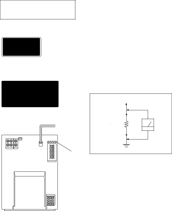
MODEL IDENTIFICATION
– Back Panel –
PART No.
SAFETY CHECK-OUT
After correcting the original service problem, perform the following safety check before releasing the set to the customer:
Check the antenna terminals, metal trim, “metallized” knobs, screws, and all other exposed metal parts for AC leakage. Check leakage as described below.
LEAKAGE TEST
The AC leakage from any exposed metal part to earth ground and from all exposed metal parts to any exposed metal part having a return to chassis, must not exceed 0.5 mA (500 microampers.). Leakage current can be measured by any one of three methods.
1.A commercial leakage tester, such as the Simpson 229 or RCA WT-540A. Follow the manufacturers’ instructions to use these instruments.
2.A battery-operated AC milliammeter. The Data Precision 245 digital multimeter is suitable for this job.
3.Measuring the voltage drop across a resistor by means of a VOM or battery-operated AC voltmeter. The “limit” indication is 0.75 V, so analog meters must have an accurate lowvoltage scale. The Simpson 250 and Sanwa SH-63Trd are examples of a passive VOM that is suitable. Nearly all battery operated digital multimeters that have a 2 V AC range are suitable. (See Fig. A)
To Exposed Metal
Parts on Set
0.15 F |
|
|
|
1.5 kΩ |
AC |
|
|
|
voltmeter |
||
|
|
|
|
|
(0.75 V) |
|
|
|
|
|
|
Earth Ground
Fig. A. Using an AC voltmeter to check AC leakage.
MODEL |
PARTS No. |
|
|
|
|
AEP, UK, German and |
4-993-619-1 |
|
North European models |
||
|
||
|
|
|
Malaysia and Singapore models |
4-993-619-2 |
|
|
|
|
Hong Kong model |
4-993-619-3 |
|
|
|
|
US model |
4-993-619-4 |
|
|
|
|
Tourist model |
4-993-619-6 |
– 5 –
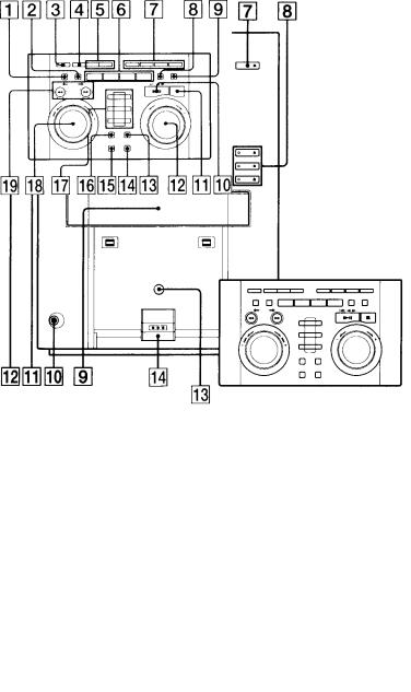
LOCATION OF CONTROLS
– Main Unit (HCD-MD515) –
– Detachable Controller (RM-MD515) –
1 EDIT/NO button
2 ENTER/YES button
3 POWER button
4PRESET EQ button
5CLOCK/TIMER SET button CLOCK/TIMER SELECT button
6TAPE button MD button CD button
TUNER (BAND) button
SECTION 2
GENERAL
1 GROOVE button and indicator
2 Fluorescent indicator tube
3POWER button
4 Remote sensor (for optional remote controller)
5MD slots
6 MD 1 to 3 indicator
7MD 6button
8 CD 1 to 3 6(open/close) button and indicator 9 CD disc tray
!º PHONES jack !¡ DIMMER button
!™ DBFB button and indicator
!£ Remote sensor (for detachable controller) !¢ Detachable controller terminal
7MANUAL, CONTINUE button AUTO, SHUFFLE button PRESET, PROGRAM button
STEREO/MONO, REPEAT button
8FUNCTION button
9 DISPLAY button !º ^button
!¡ pbutton
!™ VOLUME dial !£ DISC SKIP button
!¢ REC/CD-MD SYNC button ! REC IT button
!§ CD LOOP button !¶ MD/CD 1 to 3 button
!• MULTI JOG dial !ª 0Nbutton
)nbutton
– 6 –
This section is extracted from instruction manual.
– 7 –
SECTION 3
DISASSEMBLY
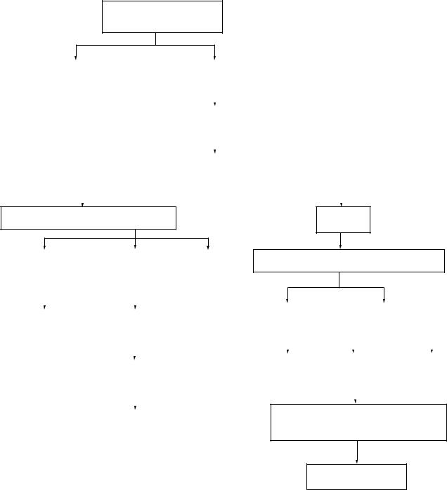
∙ This set can be disassembled in the order shown below.
DETACHABLE CONTROLLER (RM-MD515)
(Page 9)
CABINET (REAR) ASS’Y |
|
|
|
CASE |
|
|
|
||
(DETACHABLE CONTROLLER) |
|
|
|
(Page10) |
|
|
|
||
(Page 9) |
|
|
|
|
|
|
|
|
|
|
|
|
|
|
|
|
|
||
|
|
|
|
|
|
|
|
|
|
|
|
|
|
|
|
|
|
||
|
|
|
|
|
|
|
|
|
|
|
|
|
|
FRONT PANEL SECTION |
|
|
|||
|
|
|
|
(Page 10) |
|
|
|||
|
|
|
|
|
|
|
|
||
|
|
|
|
|
|
|
|
||
|
|
|
|
|
|
|
|
|
|
|
|
|
|
MAIN BOARD, SUB BOARD |
|
|
|||
|
|
|
|
(Page 11) |
|
|
|||
|
|
|
|
|
|
|
|
|
|
|
|
|
|
|
|
|
|
|
|
|
|
|
|
|
|
|
|
|
|
MD MECHANISM DECK SECTION (MDM-C1D)
(Page 11)
HOLDER (FN), |
|
|
|
MD BASE UNIT |
|
|
MOTOR (HEAD) |
||||||
|
|
|
(MBU-C1) |
|
|
ASS’Y (M905) |
|||||||
CHASSIS (TOP) |
|
|
|
|
|
||||||||
|
|
|
(Page 14) |
|
|
(Page 13) |
|||||||
(Page 12) |
|
|
|
|
|
||||||||
|
|
|
|
|
|
|
|
|
|
||||
|
|
|
|
|
|
|
|
|
|
|
|
|
|
|
|
|
|
|
|
|
|
|
|
|
|
|
|
|
|
|
|
|
|
|
|
|
|
|
|
|
|
CHASSIS (ELEVATOR) |
|
|
|
BD (MD) BOARD |
|
|
|
|
|||||
(NEW) ASS’Y |
|
|
|
(Page 14) |
|
|
|
|
|||||
(Page 13) |
|
|
|
|
|
|
|
|
|
|
|||
|
|
|
|
|
|
|
|
|
|
||||
|
|
|
|
|
|
|
|
|
|
|
|
|
|
|
|
|
|
|
|
|
|
|
|
|
|
||
|
|
|
|
|
|
|
|
|
|
|
|
|
|
|
|
|
|
OVER WRITE HEAD (HR901) |
|
|
|||||||
|
|
|
|
(Page 15) |
|
|
|
||||||
|
|
|
|
|
|
|
|
|
|
|
|
|
|
|
|
|
|
|
|
|
|
|
|
|
|
|
|
|
|
|
|
|
|
|
|
|
|
|
|
|
|
|
|
OPTICAL PICK-UP (KMS-260A/J1N) (for MD) |
|
||||||||||
|
|
(Page 15) |
|
|
|
||||||||
|
|
|
|
|
|
|
|
|
|
|
|
|
|
AMP BOARD
(Page 16)
CD MECHANISM DECK SECTION (CDM48-5BD29) (Page 16)
STOCKER ASS’Y |
|
CD BASE UNIT (BU-5BD29) |
|
||||||||
(Page 17) |
|
(Page 18) |
|
|
|
||||||
|
|
|
|
|
|
|
|
|
|
|
|
|
|
|
|
|
|
|
|
|
|
|
|
|
|
|
|
|
|
|
|
|
|
|
|
|
|
|
|
|
|
|
|
|
|
|
|
TRAY (SUB) |
|
|
BD (CD) BOARD |
|
OPTICAL |
||||||
ASS’Y |
|
|
(Page 19) |
|
PICK-UP CLEANING |
||||||
(Page 17) |
|
|
|
|
|
|
|
(Page 18) |
|||
|
|
|
|
|
|
|
|||||
|
|
|
|
|
|
|
|
|
|
|
|
|
|
|
|
|
|
|
|
|
|
|
|
OPTICAL PICK-UP (KSS-213BA/F-NP) (for CD), SLED MOTOR (M102)
(Page 19)
SPINDLE MOTOR (M101) (Page 20)
– 8 –
Note: Follow the disassembly procedure in the numerical order given.
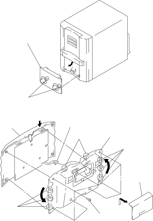
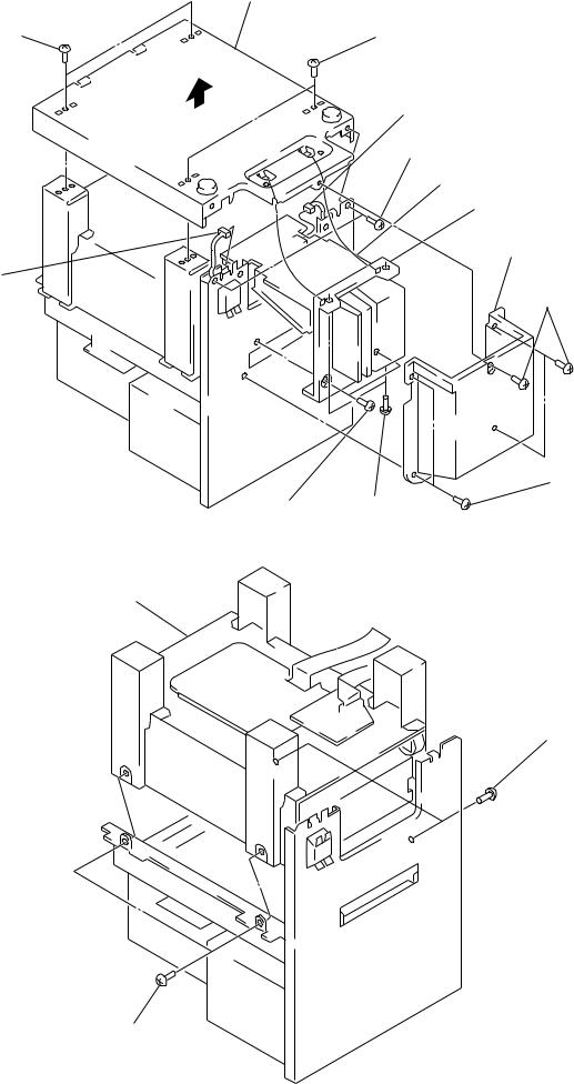
DETACHABLE CONTROLLER (RM-MD515)
2Detachable controller (RM-MD515) to direction of the arrow.
1 two claws
CABINET (REAR) ASS’Y (DETACHABLE CONTROLLER)
3 Hold the arrow B |
B |
5 connector |
of cabinet (front) ass’y. |
|
(CN2) |
4 Remove eighth claws as turn the cabinet (rear) ass’y
to direction of the arrow C.
two claws
three claws
C
1 Remove the battery case lid to direction of the arrow A.
C
A
three claws
2 seventh screws
(P2 × 4)
– 9 –
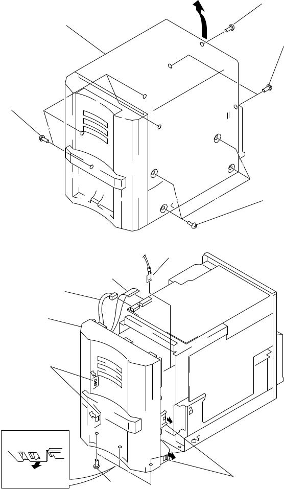
CASE
3Remove the case to direction of the arrow.
1four screws
(case 3TP2)
FRONT PANEL SECTION
1 connector
(CN200)
5 front panel section
4 two claws
4 claw
2 earth lead
1 flat wire (19 core) (CN400)
4 two claws
3 three screws
(BV3 × 8)
2screw (BV3 × 8)
2two screws (BV3 × 8)
1four screws
(case 3TP2)
– 10 –

MAIN BOARD, SUB BOARD |
1 flat wire (19 core) |
||
|
|
|
|
|
|
|
(CN401) |
|
|
1 flat wire (11 core) |
|
|
3 connector |
(CN101) |
|
1 connector |
(CN300) |
|
|
|
|
|
|
(CN920) |
|
|
|
2 two screws (BV3 × 8)
5 MAIN board
1 connector
(CN112)
6 flat wire (17 core)
(CNP13)
1connector
(CN900)
9 SUB board
4 two PC board holders
2 screw (BV3 × 8)
7 screw (BV3 × 8)
6 connector (CN912)
8 PC board holder
1 connector (CN911)
6 flat wire (23 core) (CN500)
7 two screws
(BV3 × 8)
6 flat wire (17 core)
(CN601)
6flat wire (23 core) (CN600)
MD MECHANISM DECK SECTION (MDM-C1D)
4 cover (MDM)
3 screw
(BV3 × 8)
3 two screws
(BV3 × 8) 3 screw (BV3 × 8)
1 two screws |
2 REG 5V, 7V board |
5 two screws |
|
||
(BV3 × 8) |
|
(BV3 × 8) |
5 two screws (BV3 × 8)
6MD mechanism deck section (MDM-C1D)
– 11 –
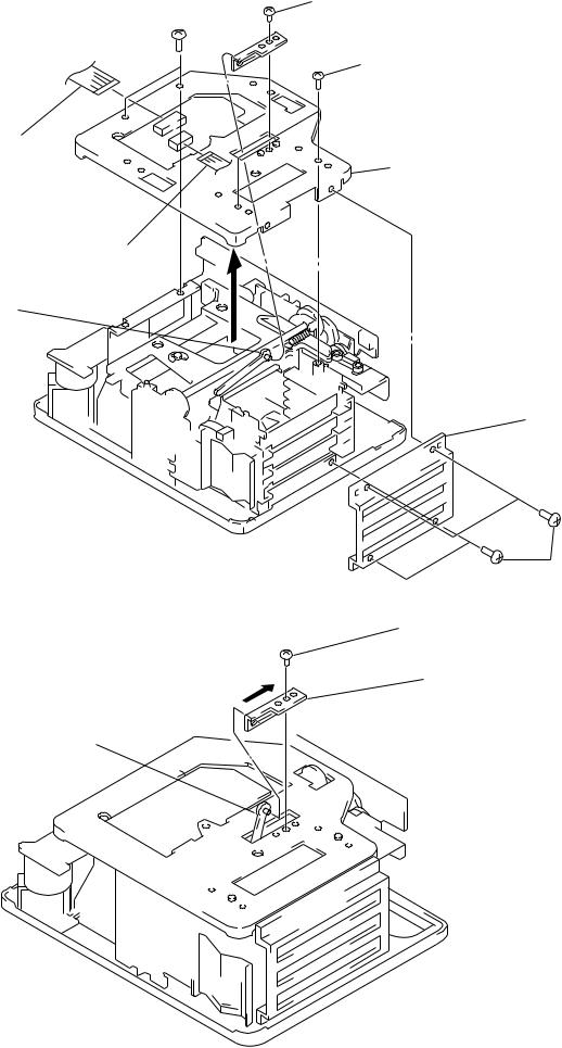
HOLDER (FN), CHASSIS (TOP)
7two screws
(BVTT2.6 × 5) 
3 flat wire (13 core)
(CNP12)
3flat wire (7 core) (CNP15)
5 lever (S) ass’y
NOTE FOR INSTALLATION OF BRACKET (3)
1 Lift up the lever (S) ass’y.
2 Hang the lever (S) ass’y for bracket (3).
3 Slide the lever (S) ass’y to direction of the arrow.
lever (s) ass’y
4screw
(BVTT2.6 × 5)
 6 bracket (3)
7 two screws (PTP2 × 5)
8 chassis (TOP)
2 holder (FN)
1 four screws
(BVTT2.6 × 5)
screw (BVTT2.6 × 5)
bracket (3)
– 12 –
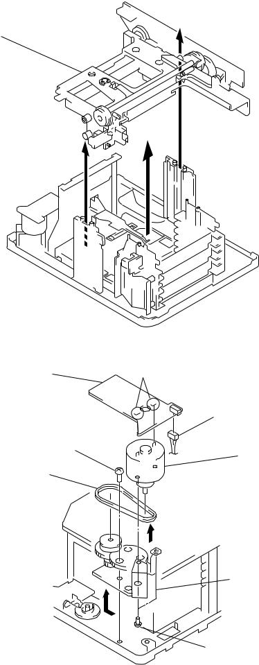
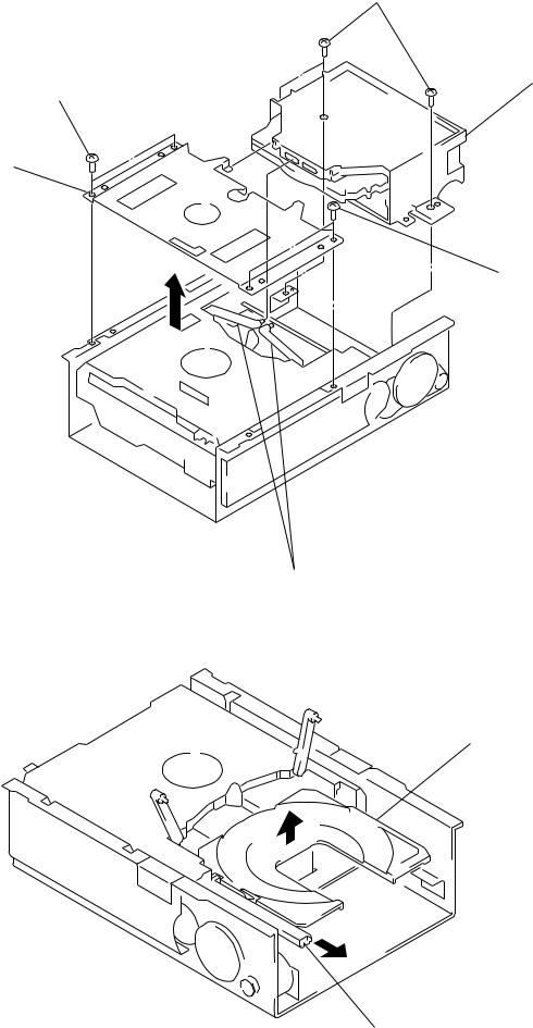
CHASSIS (ELEVATOR) (NEW) ASS’Y
1Remove the chassis (elevator) (new) ass’y to direction of the arrow.
MOTOR (HEAD) ASS’Y (M905)
8 MOTOR RELAY board
3 screw (BVTT2.6 × 5)
2 belt A
7 Break the soldering of motor.
1 connector (CNP19)
6 Remove the motor (head)
ass’y to direction of the arrow B.
 B
B
4 Remove the chassis (head gear) ass’y to direction of the arrow A.
A
5two screws (P2 × 2)
– 13 –
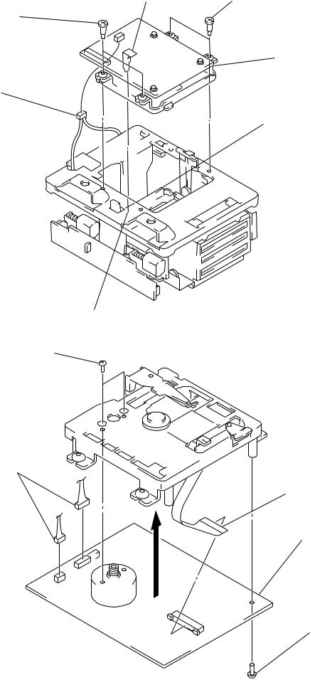
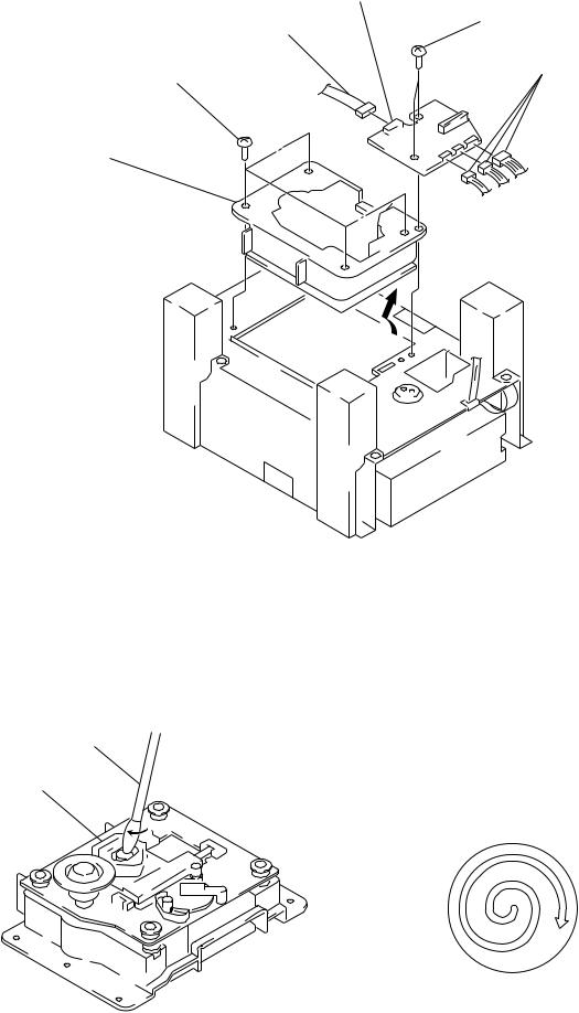
MD BASE UNIT (MBU-C1)
1 two step screws
3connector (CN108)
BD (MD) BOARD
2two precision screws (P1.7 × 2.5)
1two connectors (CN104, 109)
over write head
Take care not to catch.
1 two step screws
2MD base unit (MBU-C1)
chassis (elevator)
5OP translation flexible board (CN101)
4 BD (MD) board
3 screw (BTP2 × 6)
– 14 –
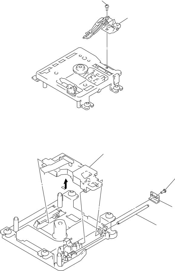
OVER WRITE HEAD (HR901)
1screw (P1.7 × 2.5)
2 over write head (HR901)
OPTICAL PICK-UP (KMS-260A/J1N) (for MD)
4 Remove the optical pick-up (KMS260A/J1N) (for MD) to direction of the arrow.
1 screw
(M1.7 × 1.4)
2 stopper
3 shaft (main)
– 15 –
AMP BOARD |
6 chassis |
5 two screws
(BV3 × 8)
7connector
(CN802)
3 two screws (BV3 × 8)
CD MECHANISM DECK SECTION (CDM48-5BD29)
2 CD mechanism deck section
(CDM48-5BD29)
1two screws (BV3 × 8)
5two screws
(BV3 × 8)
7 connector (CN801)
5 two screws (BV3 × 8)
8 AMP board
4 Pull the heat sink.
2 cover (back)
1 three screws (BV3 × 8)
1 two screws
(BV3 × 8)
3 two screws (BVTT3 × 8)
1 two screws (BV3 × 8)
– 16 –
STOCKER ASS’Y
1 two screws (BVTT3 × 6)
2Remove the bracket (sub chassis) to
direction of the arrow.
TRAY (SUB) ASS’Y
4three screws (BVTT3 × 6)
5 stocker ass’y
1 two screws
(BVTT3 × 6)
3 two levers (stock)
2 tray (sub) ass’y
1 Pull the slider (selection).
– 17 –
CD BASE UNIT (BU-5BD29)
4 four screws (BV3 × 8)
5Remove the CD base unit (BU-5BD29) to direction of the arrow.
OPTICAL PICK-UP CLEANING
applicator
optical pick-up
|
3 CDM board |
1 connector |
2 two screws |
(CN691) |
(BV3 × 8) |
|
1 three connectors |
|
(CN692, 693, 694) |
Note 1: In cleaning the lens, do not apply an excessive force. As the optical pick-up is vulnerable, application of excessive force could damage the lens holder.
Note 2: In cleaning, do not use a cleaner other than exclusive cleaning liquid (KK-91 or isopropyl alcohol).
Note 3: Wipe the objective lens spirally from center toward outside. (See Figure A)
(Figure A)
– 18 –
BD (CD) BOARD
1 two screws
1 two screws (PTPWH M2.6 × 6)
(PTPWH M2.6 × 6)
|
2 optical pick-up section |
3 two springs |
|
|
3 two springs |
5 screw |
|
(BVTP2.6 × 8) |
4 flat wire (16 core) |
|
|
|
(CN101) |
|
7 BD (CD) board |
6Remove the four solders.
limit switch
(S101)
OPTICAL PICK-UP (KSS-213BA/F-NP) (for CD), SLED MOTOR (M102)
3 optical pick-up (KSS-213 BA/F-NP) (for CD)
4 two screws (P 2 × 3)
2 sled shaft
1 claw
5 sled motor
(M102)
– 19 –

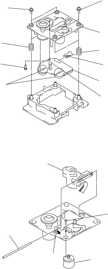
SPINDLE MOTOR (M101)
4 gear (M)
6 Turn the lever.
8 spindle motor
5 claw
(M101)
2 claw
|
3 Turn the lever. |
1 two insulators (BU) |
1 two insulators (BU) |
|
|
|
7 flatness gear (P) |
– 20 –
SECTION 4 TEST MODE
4-1. PRECAUTIONS FOR USE OF TEST MODE
1.The erasing-protection tab is not detected in the test mode. Therefore, operating in the recording laser emission mode and pressing the REC/CD-MD SYNC button, the recorded contents will be erased regardless of the position of the tab. When using a disc that is not to be erased in the test mode, be careful not to enter the continuous recording mode and traverse adjustment mode.
But “CREC MODE”, “EF MO CHECK” and “EF MO ADJUST” is detect the erasing-protection tab and recording laser power off.
2.Using MD slot is “DISC 1” only.
4-1-1. Recording Laser Emission Mode and Operating
Button
1.Continuous recording mode (CREC MODE)
2.Traverse adjustment mode (EF MO ADJUST)
3.Laser power adjustment mode (LDPWR ADJUST)
4.Laser power check mode (LDPWR CHECK)
5.When pressing the REC/CD-MD SYNC button.
6.Traverse checking mode (EF MO CHECK)
4-2. SETTING THE TEST MODE
1.Turn on the set, and select the MD function.
2.Place the MD in “NO DISC” status (No disc present in stocker and inside of set)
3.Press DBFB button, DIMMER button, and MD6 button simultaneously to activate the Test mode.
When the Test mode is activated. “TEMP ADJUST” is displayed on fluorescent indicator tube.
4-3. LOADING/UNLOADING A DISC IN TEST MODE
1.In the Test mode, use the slot 1 only. (Do not load a disc in other slots.)
2.When a disc is loaded in slot 1, in several seconds it will be automatically pulled in.
3.To unload a disc, press MD6 button .
4.To load a disc again, press MD6 button .
5.In the Test mode, MD1, 2, 3 LEDs do not light regardless of whether a disc is present or not.
4-4. RELEASING THE TEST MODE
Press the REPEAT button, and the set returns to normal mode. (If REPEAT button is pressed with a disc loaded, the disc is automatically ejected.)
4-5. BASIC OPERATIONS OF THE TEST MODE
All operations are performed using the MULTI JOG dial, ENTER/YES button, and EDIT/NO button. The functions of these buttons and dial are as follows.
|
Table 1. |
|
|
|
|
Button & dial |
Function |
|
MULTI JOG dial |
Changes parameters and modes. |
|
ENTER/YES button |
Proceeds onto the next step. |
|
Finalizes input. |
||
|
||
|
|
|
EDIT/NO button |
Returns to previous step. |
|
Stops operations. |
||
|
||
|
|
4-6. SELECTING THE TEST MODE
Twenty six test modes are selected by turn the MULTI JOG dial.
|
Table 2. |
|
|
Display |
Contents |
TEMP CHECK |
Temperature compensation offset check |
|
|
LDPWR CHECK |
Laser power check |
|
|
EF MO CHECK |
Traverse (E-F balance) check |
EF CD CHECK |
Travers (Pre mastered disk) check |
|
|
FBIAS CHECK |
Focus bias check |
CPLAY MODE |
Continuous playback mode |
CREC MODE |
Continuous recording mode |
|
|
Scurve CHECK |
S-curve check (*1) |
VERIFY MODE |
Non-volatile memory check (*1) |
|
|
DETRK CHECK |
Detrack check |
TEMP ADJUST |
Temperature compensation offset adjustment |
|
|
LDPWR ADJUST |
Laser power adjustment |
|
|
EF MO ADJUST |
Traverse (E-F balance) adjustment |
EF CD ADJUST |
Traverse (Pre mastered disk) adjustment |
|
|
FBIAS ADJUST |
Focus bias adjustment |
EEP MODE |
Non-volatile memory mode (*1) |
|
|
MANUAL CMD |
Manual command transfer mode (*1) |
|
|
SVDATA READ |
Data reading out mode (*1) |
ERR DP MODE |
Operation of error histories memory |
|
|
SLED MOVE |
Operation of sled motor (*1) |
ACCESS MODE |
Access check (*1) |
|
|
0920 CHECK |
Outermost periphery check (*1) |
|
|
WRITE sure? |
Non-volatile memory initialize (*1) |
HEAD ADJUST |
HEAD adjustment check (*1) |
|
|
CPLAY2MODE |
Continuous playback mode (*1) |
CREC2MODE |
Continuous recording mode (*1) |
•For detailed description of each adjustment mode, refer to the “5. ELECTRICAL ADJUSTMENTS” (page 24).
•If a different adjustment mode has been selected by mistake, press the EDIT/NO button to exit from it.
*1: Scurve CHECK, VERIFY CHECK, EEP MODE, MANUAL CMD, SVDATA READ, SLED MOVE, ACCESS MODE, 0920 CHECK, Write sure?, HEAD ADJUST, CPLAY2MODE, and CREC2MODE are not used in servicing. If set accidentally, press the POWER button immediately to exit it.
– 21 –
4-7. OPERATING THE CONTINUOUS PLAYBACK MODE
4-7-1. Entering the Continuous Playback Mode
1.Set the disc in the slot 1 of unit. (In several seconds it will be automatically pulled in.) (Whichever recordable discs or discs for playback only are available.)
2.Turn the MULTI JOG dial and display “CPLAY MODE”.
3.Press the ENTER/YES button to change the display to “CPLAY MID”.
4.When access completes, the display changes to
“C = 


 AD=
AD= 
 )”.
)”.
Note: The numbers “  ” displayed show you error rates and ADER.
4-7-2. Changing the Parts to be Played-back
1.Press the ENTER/YES button during continuous playback to change the display as below.
CPLAY MID 
 CPLAY OUT
 CPLAY IN

4-8. OPERATING THE CONTINUOUS RECORDING MODE
4-8-1. Entering the Continuous Recording Mode
1.Set the MO disc in the slot 1 of unit. (Refer to note 3.)
2.Turn the MULTI JOG dial and display “CREC MODE”.
3.Press the ENTER/YES button to change the display to “CREC MID”.
4.When access completes, the display changes to “CREC
( |
)” and |
REC |
lights up. |
Note: The numbers “  ” displayed shows you the recording position address.
4-8-2. Changing the Parts to be Recorded
1.When the ENTER/YES button is pressed during continuous recording, the display changes as below. (“PROGRAM” indication turns off during change-over of display.)
CREC MID 
 CREC OUT
 CREC IN
2. When access completes, the display changes to “C1= 


 AD=
AD=
 ”.
”.
Note: The numbers “  ” displayed show you error rates and ADER.
4-7-3. Ending the Continuous Playback Mode
1.Press the EDIT/NO button. The display will change to “CPLAY MODE”.
2.Press the MD6 button and remove the disc.
Notes:
1.The playback start address for IN, MID, and OUT are as follows.
IN |
: 40h cluster |
MID |
: 300h cluster |
OUT |
: 700h cluster |
In case you want to display the address of the playback position on the
display, press the |
DISPLAY |
button and display “CPLAY ( |
)”. |
||
2. The |
EDIT/NO |
button can be used to stop playing anytime. |
|
||
2. When access completes, the display changes to “CREC
( |
)” and |
REC |
lights up. |
Note: The numbers “  ” displayed shows you the recording position address.
4-8-3. Ending the Continuous Recording Mode
1. |
Press the |
EDIT/NO |
button. The display will change to “CREC |
||||
|
|
|
|
|
|
|
|
|
MODE” and |
REC |
|
goes off. |
|||
2. |
Press the |
|
button and remove the disc. |
||||
MD 6 |
|||||||
Notes:
1.The recording start address for IN, MID, and OUT are as follows.
IN |
: 40h cluster |
MID |
: 300h cluster |
OUT |
: 700h cluster |
2.The EDIT/NO button can be used to stop recording anytime.
3.During the test mode, the erasing-protection tab will not be detected. Therefore be careful not to set the continuous recording mode when a disc not to be erased is set in the unit.
4.Do not perform continuous recording for long periods of time above 5 minutes.
5.During continuous recording, be careful not to apply vibration.
4-9. EEP MODE
This mode reads and writes the contents of the non-volatile memory.
It is not used in servicing. If set accidentally, press the
EDIT/NO button immediately to exit it.
– 22 –
4-10. FUNCTIONS OF OTHER BUTTONS
|
Table 3. |
|
|
|
|
Button |
Contents |
|
|
|
|
|
Sets continuous playback when pressed in the STOP |
|
fl |
state. (servo all on) |
|
When pressed during continuous playback, the tracking |
||
|
||
|
and sled servo turns on/off. |
|
|
|
|
p |
Stop continuous playback and continuous recording. |
|
(servo all off) |
||
|
||
|
|
|
) |
The sled moves to the outer circumference only when |
|
this is pressed. |
||
|
||
|
|
|
0 |
The sled moves to the inner circumference only when |
|
this is pressed. |
||
|
||
|
|
|
REC/CD-MD |
Turns recording on/off when pressed during continuous |
|
SYNC |
playback. |
|
|
|
|
SHUFFLE |
Switches between the pit and groove modes when |
|
pressed. |
||
|
||
|
|
|
CONTINUE |
Switches between the CLV-S (pull-in mode) and CLV- |
|
A (playing servo) modes when pressed. (Switches the |
||
|
spindle servo mode.) |
|
|
|
|
DISPLAY |
Switches the display when pressed. |
|
Returns to previous step. Stop operations. |
||
|
||
|
|
|
REPEAT |
Releasing the test mode |
|
|
|
|
6 |
Disc eject |
|
|
|
Note: The erasing-protection tab in not detected during the test mode. Recording will start regardless of the position of the erasing-protec- tion tab when the REC/CD-MD SYNC button is pressed.
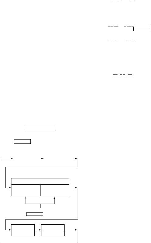
4-11. TEST MODE DISPLAYS
Each time the DISPLAY button pressed, the display changes in
the following order.
Mode |
|
|
Error rate |
|
display |
|
|
display |
|
|
|
|
|
|
Address display |
|
ADIP address |
SUB Q address |
display |
display |
Change over the display with the
SHUFFLE button.
Auto gain |
IVR |
display |
display |
Note: Auto gain display and IVR display are not used in servicing.
1.MODE display
Displays “TEMP ADJUST”, “CPLAY MODE”, etc..
2.Error rate display
Error rates are displayed as follows.
C1= 


 AD=
AD= 


C1= : Indicates C1 error AD= : Indicates ADER
3.Address display
Address are displayed as follows.
h= 


 a=
a= 


 (MO groove)
With this display, if SHUFFLE button is pressed, the following will be displayed.
h= 


 s=
s= 


 (MO pit and CD) h=: Header address
a=: ADIP address
s=: SUB Q address
Note: “—” is displayed when the address cannot be read.
4.Auto gain display
Auto gain are displayed as follows. AG = 


 /
/ 


 [
[ 


 ]
]
|
|
|
A |
|
B C |
|
|
||
|
A= Focus servo gain coefficient |
|
|
||||||
|
B= Tracking servo gain coefficient |
|
|||||||
|
C= [OK] or [NG] or [ - -] (not converged) |
|
|||||||
4-12. MEANINGS OF OTHER DISPLAYS |
|
||||||||
|
|
|
|
|
|
Table 4. |
|
|
|
|
|
|
|
|
|
|
|
|
|
|
|
|
|
|
|
Contents |
|
||
|
Display |
|
|
||||||
|
|
|
|
|
|
|
|||
|
|
|
|
|
|
Light |
|
Off |
Blinking |
|
|
|
|
|
|
||||
|
|
|
|
|
|
|
|
|
|
|
|
|
|
|
|
|
|
|
|
( |
|
|
|
During continuous |
|
Stop state |
— |
||
|
|
|
playback (servo all on) |
|
(servo all off) |
||||
|
|
|
|
|
|
|
|
||
|
|
|
|
|
|
|
|
|
|
|
|
|
|
|
|
|
|
Recording |
|
|
|
REC |
|
|
|
Recording mode on |
|
— |
|
|
|
|
|
|
|
mode off |
|||
|
|
|
|
|
|
|
|
|
|
|
|
|
|
|
|
|
|
||
|
ALL DISCS |
|
CLV lock state |
|
CLV unlock state |
— |
|||
|
|
|
|
|
|
|
|
||
|
TRACK |
|
Pit mode |
|
Groove mode |
— |
|||
|
|
|
|
|
|
|
|
|
|
|
|
DISC |
|
High reflection rate |
|
Low reflection rate |
— |
||
|
|
|
disc |
|
disc |
||||
|
|
|
|
|
|
|
|
||
|
|
|
|
|
|
|
|
|
|
|
|
|
|
|
|
Spindle servo |
|
Spindle servo |
— |
|
REPEAT |
|
CLV-S |
|
CLV-A |
||||
|
|
|
|
|
|
(pull-in mode) |
|
(playing mode) |
|
|
|
|
|
|
|
|
|
||
|
LEVEL- |
|
ABCD adjustment |
|
Not adjustment |
— |
|||
|
|
SYNC |
|
completed |
|
||||
|
|
|
|
|
|
||||
|
|
|
|
|
|
|
|
|
|
|
|
|
|
|
|
|
|
|
Focus |
|
SHUFFLE |
|
Focus auto gain |
|
— |
auto gain |
|||
|
|
successful |
|
suc- |
|||||
|
|
|
|
|
|
|
|
||
|
|
|
|
|
|
|
|
|
cessful. |
|
|
|
|
|
|
|
|
|
|
|
PROGRAM |
|
Tracking auto gain |
|
— |
Tracking |
|||
|
|
|
auto gain |
||||||
|
|
successful |
|
||||||
|
|
|
|
|
|
|
|
failed. |
|
|
|
|
|
|
|
|
|
|
|
|
|
|
|
|
|
|
|
|
|
– 23 –
SECTION 5
ELECTRICAL ADJUSTMENTS
MD SECTION
1. PRECAUTIONS FOR CHECKING LASER DIODE EMISSION
To check the emission of the laser diode during adjustments, never view directly from the top as this may lose your eyesight.
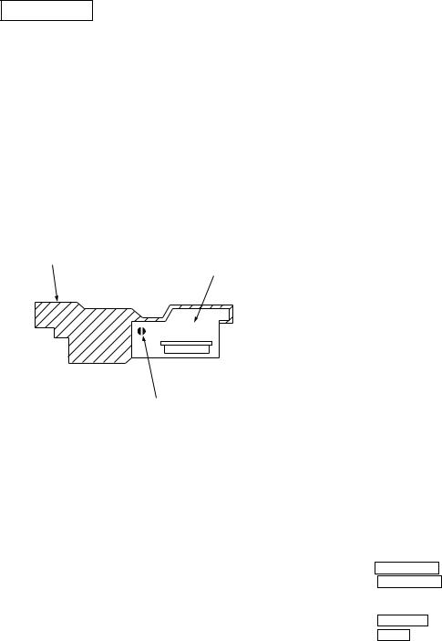
2. PRECAUTIONS FOR USE OF OPTICAL PICK-UP (KMS-260A)
As the laser diode in the optical pick-up is easily damaged by static electricity, solder the laser tap of the flexible board when using it.
Before disconnecting the connector, desolder first. Before connecting the connector, be careful not to remove the solder. Also tale adequate measures to prevent damage by static electricity. Handle the flexible board with care as it breaks easily.
Pick-up
Flexible board
Laser tap
Optical pick-up flexible board
3.PRECAUTIONS FOR ADJUSTMENTS
1)When replacing the following parts, perform the adjustments and checks with ®in the order shown in the following table.
|
|
Table |
1. |
|
||
|
|
|
|
|
|
|
|
|
Optical |
|
|
BD (MD) board |
|
|
|
Pick-up |
IC171 |
|
D101 |
IC101, IC121, IC192 |
|
|
|
|
|
|
|
1. |
Temperature |
× |
|
|
|
|
|
compensation |
® |
|
® |
® |
|
|
offset adjustment |
|
|
|
|
|
|
|
|
|
|
|
|
2. |
Laser power |
® |
® |
|
× |
® |
|
adjustment |
|
||||
|
|
|
|
|
|
|
|
|
|
|
|
|
|
3. |
Traverse |
® |
® |
|
× |
® |
|
adjustment |
|
||||
|
|
|
|
|
|
|
|
|
|
|
|
|
|
4. |
Focus bias |
® |
® |
|
× |
® |
|
adjustment |
|
||||
|
|
|
|
|
|
|
|
|
|
|
|
|
|
5. |
Error rate check |
® |
® |
|
× |
® |
2)Set the test mode when performing adjustments. After completing the adjustments, exit the test mode.
3)Perform the adjustments in the order shown.
4)Use the following tools and measuring devices.
∙Test disc (CD for playback only) TDYS-1 (Parts No. 4-963-646-01)
∙Laser power meter LPM-8001 (Parts No. J-2501-046-A)
∙Oscilloscope (Measure after preforming CAL of prove.)
∙Digital voltmeter
∙Thermometer
5)When observing several signals on the oscilloscope, etc., make sure that VC and ground do not connect inside the oscilloscope.
(VC and ground will become short-circuited)
4.CREATING MO CONTINUOUSLY RECORDED
DISC
* This disc is used in focus bias adjustment and error rate check. The following describes how to create a MO continuous recording disc.
1.Insert a MO disc (blank disc) commercially available to MD slot 1.
2.Turn the MULTI JOG dial and display “CREC MODE”.
3.Press the ENTER/YES button and display “CREC MID”. “CREC (0300)” is displayed for a moment and recording starts.
4.Complete recording within 5 minutes.
5.Press the EDIT/NO button and stop recording.
6.Press the MD6 button and remove the MO disc.
The above has been how to create a continuous recording data for the focus bias adjustment and error rate check.
Note: Be careful not to apply vibration during continuous recording.
– 24 –
 Loading...