


HDC-4300
Table of contents
 Loading...
COLOR CAMERA
HDC4300
OPERATION MANUAL [English]
1st Edition (Revised 3)

Table of Contents
Overview..................................................................... 3
Features ...........................................................................3
Main Functions.................................................................3
System Configuration.......................................................6
Locations and Functions of Parts............................ 9
Accessory Attachments....................................................9
Controls and Connectors .................................................9
Preparations............................................................. 15
Attaching a Lens ............................................................15
Adjusting the Flange Focal Length.................................15
Attaching a Viewfinder ...................................................16
Attaching the Cable Clamp Belt (Supplied)....................18
Adjusting the Shoulder Pad Position..............................19
Mounting the Camera to a Tripod ..................................19
Adjustments and Settings for Shooting ................ 20
Adjusting the Black Balance and White Balance ...........20
Setting the Electronic Shutter.........................................22
Setting the Focus Assist Functions................................23
Setting the Dynamic Focus Function Detail ...................25
Setting the Kinetic Focus Function Detail ......................26
Setting the Camera Outputs ................................... 27
Viewfinder Screen Status Display.......................... 28
Menu Operations ..................................................... 30
Starting Menu Operations ..............................................30
Selecting Pages .............................................................31
Setting Menu Items ........................................................31
Editing the USER Menu .................................................32
Menu List .................................................................. 36
Menu Tree......................................................................36
OPERATION Menu ........................................................41
PAINT Menu...................................................................53
MAINTENANCE Menu ...................................................58
FILE Menu......................................................................63
DIAGNOSIS Menu .........................................................65
Appendix .................................................................. 67
Precautions ....................................................................67
Error Messages..............................................................68
Using a USB Drive ................................................... 68
Specifications .......................................................... 69
HDC4300 .......................................................................69
Optional Accessories/Related Equipment......................70
Dimensions ....................................................................70
2

Overview
The HDC4300 is a camera unit equipped with a 2/3-inch,
9.8 megapixel, 3-chip CMOS image sensor for super motion
video camera systems.
In addition to standard HD and HD high frame rate (HD-HFR)
imaging, it also supports 4K multi-format imaging.
Features
Main Functions
Various color-reproduction adjustment
functions
Adaptive-matrix function
This function controls the matrix calculation coefficients for
more accurate color conversion when shooting. It provides
accurate color conversion, even when shooting under
conditions that would otherwise exceed the color conversion
range of traditional matrix functions, such as under strong
monochromatic blue light sources.
High definition, high picture quality, and high
performance
The HDC4300 features a newly developed 2/3-inch
9.8 megapixel CMOS image sensor and newly developed
wide color gamut prism block, and a high performance digital
signal processor LSI.
It connects to an HDCU4300
Processor Unit
via optical camera cables to support various formats from HD
high-speed imaging to 4K imaging, enabling the reproduction
of high image quality, high-definition images.
(The addition of image formats is supported using options.)
1) For details about supported software versions, contact a Sony sales
representative or Sony service representative.
1)
and HDCU2000/2500 Camera Control Unit1)
1)
or BPU4000/4500 Baseband
High-speed imaging
HD format (1080P, 1080i, 720P) imaging is supported at 2×
and 3× frame rates (100, 119.88, 150, 179.82 fps) as
standard. 4×, 6×, and 8× (200, 239.76, 300, 359.64, 400,
479.52 fps) are supported using option packages.
4K image shooting
4K/23.98P, 24P, 25P, 29.97P, 50P, 59.94P, 100P, 119.88P is
supported using an option package. Pure 4K high-definition
images can be captured using a 4K 3-chip RGB-Full pixel
sensor.
And the newly developed wide color gamut prism enables
color reproduction covering the 2020 color gamut.
Focus assist functions
The camera features various focus assist functions in the
viewfinder for enhanced focusing.
When shooting in 4K in particular, the dynamic focus function
enables 4K-quality focus adjustment.
Operability and scalability
The camera is essentially the same size and weight as
HDC2500-series cameras, and accordingly features the same
advantages in usability.
The main functions and camera operation, including
connection with peripheral devices, power supply to the
camera, and intercom function, all follow that of conventional
devices.
Multimatrix color correction
In addition to the standard 6-axis matrix function, the unit has
a multimatrix function that permits you to adjust the hue and
chroma independently for color components in 16-axis
directions. This is quite useful in color matching among
multiple cameras.
Knee saturation
This compensates the change of hue and decrease in chroma
that occur in highlighted areas. This enables reproduction of
natural skin tones under strong lighting.
Low key saturation
This compensates for saturation in low-key zones. It
compensates for color reproduction in all zones, in
combination with the matrix color compensation and knee
saturation functions.
Selectable gamma table
Equipped with seven types of standard gamma tables and four
types of hyper gamma tables. Hyper gamma enables cinemalike image reproduction with wide dynamic range that cannot
be achieved with conventional video gamma.
User gamma
Gamma tables created using CvpFileEditorTM can be saved to
a “Memory Stick,” and registered in the camera from
MSU-1000/1500 and RCP-1500 series devices.
Versatile detail control functions
Skin-tone detail function/Natural skin detail
function
Like HDC2500-series cameras, this function allows control
(emphasis or suppression) of the detail level for a certain hue
or chroma area in the image, by creating a detail gate signal
from color components of your specified hue, such as skin
tones. The detail levels of three hues can be adjusted
independently at the same time.
The camera features a natural skin detail function that adjusts
the detail gate signal in order to distinguish clearly between
parts of skin you want to smooth from the parts you do not
want to smooth, such as eyebrows.
3

Detail boost-frequency control
The boost frequency can be adjusted from 20 MHz to 30 MHz.
This allows the thickness of the detail signal to be set
appropriately for the subject, thus enabling high-definition
image reproduction.
Menu-based operation function
You can make selections and settings related to viewfinder
display items, safety zone marker, center marker, and screen
size marker, etc. quickly and easily using the menu displayed
in the viewfinder or on an external monitor.
H/V ratio control
Adjusts the ratio between the applied horizontal and vertical
detail.
White/black limiter
The white and black details can be limited independently.
Focus assist functions
VF detail
Supports focusing on various scenes using a function that
adds color to the VF detail signal displayed in the viewfinder,
a function that applies modulation to flicker the VF detail
signal, and a function that changes the level of the VF detail
signal according to the zoom position.
Focus assist indicator
Displays a focusing level indicator in the viewfinder as a guide
to the focus position. This allows the focus point to be
determined easily by observing the fluctuation of the indicator.
Dynamic focus
Displays a 4K resolution-specific focus point. This displays a
marker in the viewfinder, derived from the luminance signal
and color signal, for the area where 4K resolution signal is
being output (valid when shooting in 4K only).
Focus position meter
Displays the lens focus position as a meter, when a supported
1)
lens
is attached.
This allows you to place a marker for any focus value which
acts as a guide for focus control.
1) Lenses that support serial, lens command control.
PinP function
The return video signal or HD prompter picture can be
displayed on the viewfinder in picture-in-picture mode.
Note
The PinP function cannot be used during standalone
operation.
Wide variety of input/output interfaces
In addition to 3G/HD/SD-SDI output and HD/SD-SDI input, the
HDC4300 features a wide variety of input/output interfaces,
including the following.
Network TRUNK function
The network TRUNK function (LAN port) allows for data
transmission between the camera and CCU at speeds of up to
100 Mbps.
Note
The network TRUNK transfer rate differs depending on the
video format. Jumbo frames are not supported.
HD prompter function
The HDC4300 supports an HD prompter function where
HD-SDI equivalent digital data is sent from the HDCU2000/
2500/4300 to the HDC4300, separate from the return video
signal.
Note
The HD prompter function can only be used when a single
format is selected and the network TRUNK function is set to
OFF.
Follow focus function
Enables focus control from the camera (focus demand), and
both a MSU-1000/1500 and RCP-1000/15000-series device,
when a supported lens
main control from the camera, and additional fine control from
MSU-1000/1500 and RCP-1000/1500-series devices.
1) Lenses that support serial, lens command control Ver. 1.04 or later.
1)
is attached. This allows focusing with
Various viewfinder functions
Wide variety of viewfinder display options
You can display configuration settings, in addition to operation
messages, a zebra pattern, a safety-zone marker, and a
center marker in the viewfinder. Also, there are indicators
along the top and bottom of the viewfinder, such as a tally
lamp, battery warning indicator, and an indicator that warns
you when one or more settings are not within standard range.
User-friendly operation
Spirit level display function
The HDC4300 features a spirit level function, which enables
you to display the amount of camera roll on the viewfinder or
a monitor. By checking the level of the camera, more stable
shooting can be achieved.
Carbon-graphite outer cover
The HDC4300 outer cover is made of carbon graphite.
Much lighter and stronger than plastic, it can easily withstand
intense movement under the toughest shooting conditions.
Uni-body construction with low center of gravity
The HDC4300, like the HDC2500 series, adopts a stylish
appearance with a low-slung design.
When used in combination with the HDLA1500-series Large
Lens Adaptor, it permits the viewfinder to be mounted at a low
position, making the viewfinder position closer to the optical
axis of the lens.
4

Swing handle and VF slide mechanism
A slight protrusion of the upper front part of the handle enables
stable holding of the camera while you are shooting, by
holding the front part of the handle. Furthermore, the movable
range of a front-rear slide mechanism for the viewfinder
attachment is wide to provide the best balance for shooting
with the camera on your shoulder.
The swing handle mechanism allows for mounting and usage
on the HDLA1500 series, making forward shifting with a largescale viewfinder possible. This enables the same total
longitudinal size as a standard studio-use camera, for
operability equivalent to that of a standard studio-use camera.
Adjustable shoulder pad
The position of the shoulder pad can be adjusted for stable
shooting according to the build of the camera operator, the
type of lens in use, or the shooting style.
A low-repulsion foam shoulder pad (fixed type) is available as
an option (Part No.: A-8286-346-A).
Assignable switches
The assignable switches on the side panel can be assigned to
your desired function, such as electronic color-temperature
conversion.
These switches can be synchronized with the assignable
switches on viewfinder models, such as the HDVF-EL75, and
can be used to operate the viewfinder functions, such as
magnification.
Also, two function-assignable switches are on the upper part
of the handle, and can be used to set the viewfinder functions
such as lens zoom.
USB connector
Connects to a USB flash drive for importing/exporting menu
configuration settings and other data.
Electric shock protection
This function stops the high-voltage power supply from the
camera control unit if the unit is not connected securely.
Optional accessories
You can add new functions and compatibility with other video
formats by embedding the following optional accessories.
For details about installing optional accessories, please
contact a Sony sales representative or Sony service
representative.
For specifications or more detailed information on optional
accessories, refer to the manual of each accessory.
SZC-4001/4001M/4001W 4K upgrade software
Enables shooting of 4K images.
5
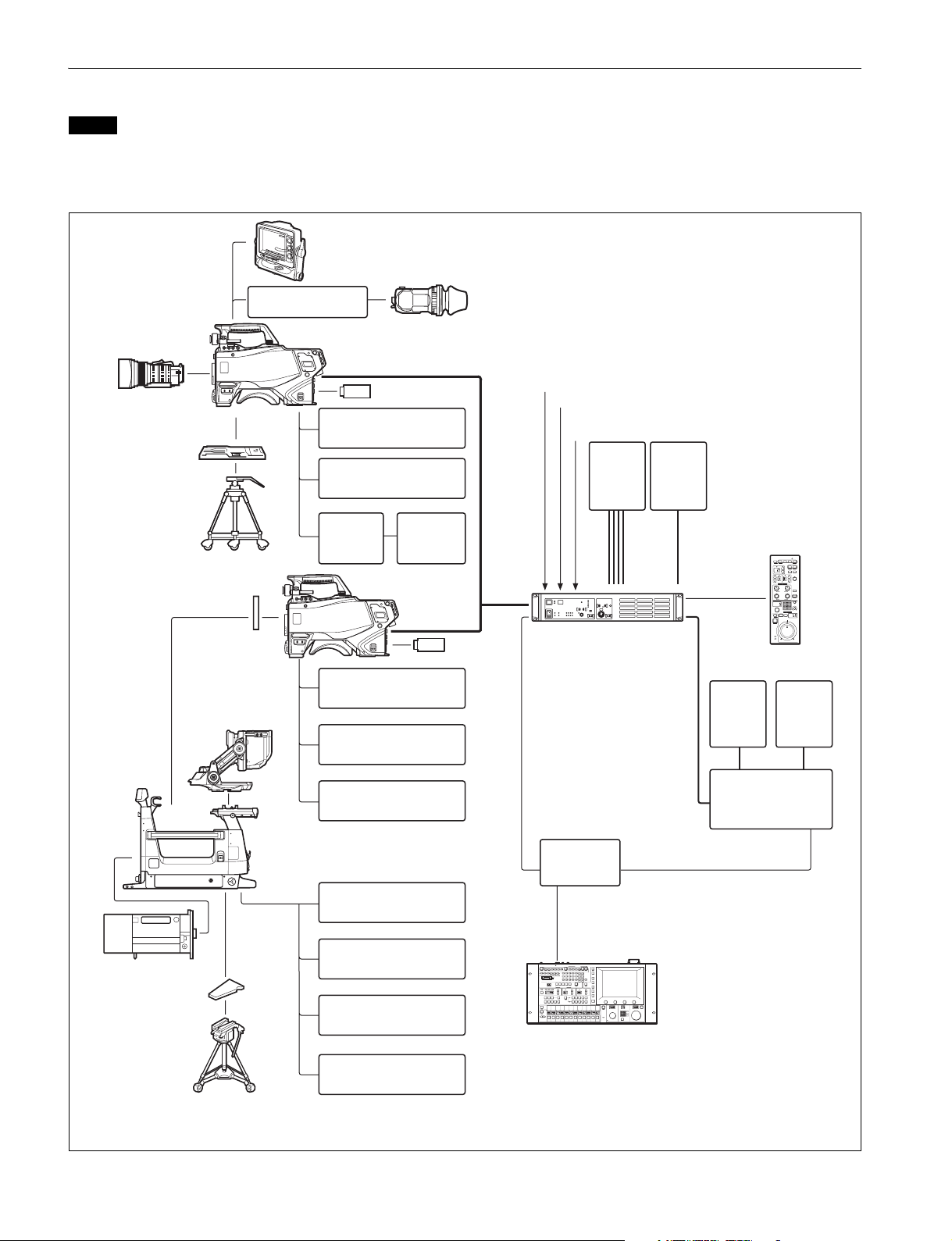
System Configuration
Note
Production of some of the peripherals and related devices shown in the figures may have been discontinued.
For advice on choosing devices, please contact your Sony dealer or a Sony sales representative.
HDCU4300 connection example
HDVF-EL75/L750/L770 Viewfinder
HDVF-20A
HDVF-200
HDVF-EL20
HDVF-EL30
Viewfinder
Lens
(for ENG/EFP)
BKW-401 Viewfinder
Rotation Bracket
HDC4300
VCT-14
Tripod Adaptor
Tr ip o d
Camera hanger
HDVF-EL70
HDVF-700A Viewfinder
USB flash drive
CAC-6 Return Video
Selector
Intercom Headset
CAC-12
Microphone
Holder
a)
CAC-6 Return Video
Selector
Intercom Headset
Microphone
Microphone
HDC4300
USB flash drive
Sync signal input
Optical fiber cable
HDCU4300
Camera Control Unit
LAN cable
Return video input
Intercom microphone input
4K Video
Monitor
BNC×4
2K Video
Monitor
b)
BNC
CCA-5
RCP-1000 series
BNC
Remote Control Panel
Video
Monitor
Video Router
Wavefor m
Monitor
HDLA1500 series Large
Lens
(for studio camera)
V-wedge shoe
(supplied with
tripod)
Tr i p od
Lens Adaptor
CAC-6 Return Video
Selector
Intercom Headset
Microphone
BKP-7911
Script Holder
Hub
LAN cable
MSU-1000 series
Master Setup Unit
a) Supplied with HDLA1500 series (Part number: A-1128-405-A)
b) The SZC-4002/4002M/4002W HFR software option must be installed for HFR (High Frame Rate) imaging at speeds up to 4×, 6×, and 8×.
6
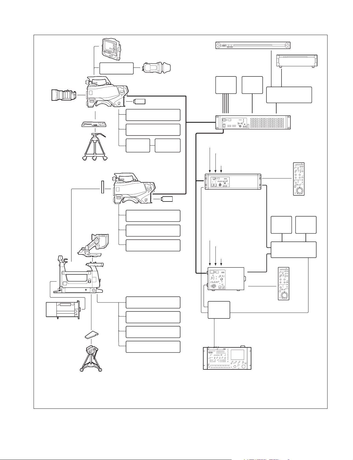
BPU4500 connection example
BKW-401 Viewfinder
Rotation Bracket
Lens
(for ENG/EFP)
VCT-14 Tripod
Adaptor
Tripod
HDC4300
HDVF-EL75/L750/L770
Viewfinder
Optical fiber cable
USB flash drive
CAC-6 Return Video
Selector
Intercom Headset
CAC-12
Microphone
Holder
Microphone
HDVF-20A
HDVF-200
HDVF-EL20
HDVF-EL30
Viewfinder
PWS-100NM1
IP Live System Manager
Station
4K Video
Monitor
BNC × 4
BPU4500
Baseband Processor Unit
Sync signal input
Return video input
Intercom microphone
input
2K Video
Monitor
BNC
NXL-FR318 Signal
Processing Unit
Network Switch
Optical fiber cable
b)
c)
Camera hanger
HDVF-EL70
HDVF-700A
Viewfinder
Lens
(for studio camera)
V-wedge shoe
(supplied with
tripod)
Tr ip o d
a)
HDLA1500-series
Large Lens Adaptor
HDC4300
USB flash drive
CAC-6 Return Video
Selector
Intercom Headset
Microphone
CAC-6 Return Video
Selector
Intercom Headset
Microphone
BKP-7911
Script Holder
Optical fiber cable
HDCU2000
Camera Control Unit
LAN cable
Sync signal input
Return video input
Intercom
microphone input
HDCU2500
Camera Control Unit
Hub
LAN cable
CCA-5
RCP-1000 series
Remote Control Panel
BNC
Video
Monitor
Video Router
BNC
CCA-5
RCP-1000 series
Remote Control Panel
MSU-1000 series
Master Setup Unit
Wavefor m
Monitor
a) Supplied with HDLA1500 series (Part number: A-1128-405-A)
b) The SZC-4002/4002M/4002W HFR software option must be installed for HFR (High Frame Rate) imaging at speeds up to 4×, 6×, and 8×.
c) Install NXLK-IP40F SDI-IP converter board (option).
7
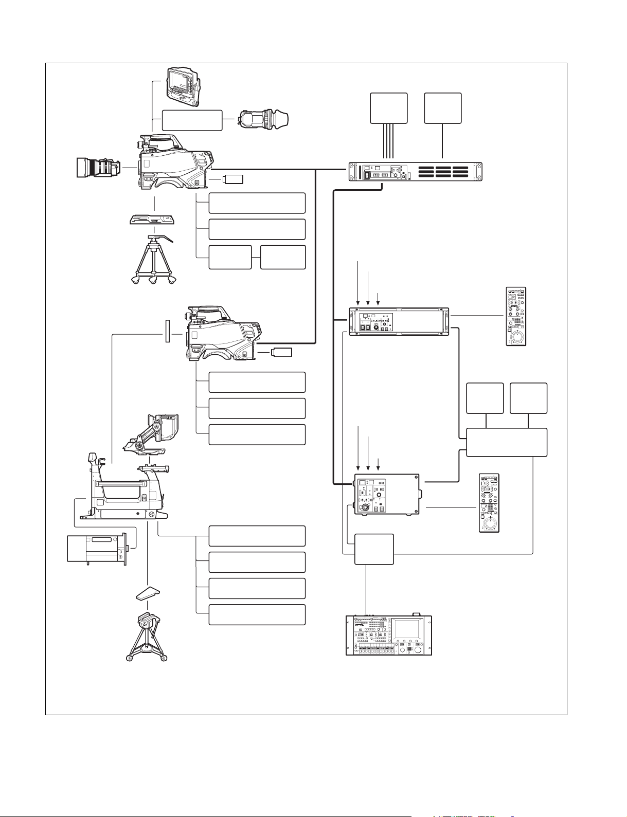
BPU4000 connection example
BKW-401 Viewfinder
Rotation Bracket
Lens
(for ENG/EFP)
HDC4300
HDVF-EL75/L750/L770
Viewfinder
Optical fiber cable
HDVF-20A
HDVF-200
HDVF-EL20
HDVF-EL30
Viewfinder
4K video
monitor
BNC×4
2K video
monitor
BNC
VCT-14 Tripod
Attachment
Tripod
Camera hangers
a)
HDVF-EL70
HDVF-700A
Viewfinder
USB drive
CAC-6 Return Video
Selector
Intercom headset
CAC-12
Microphone
Holder
Microphone
HDC4300
CAC-6 Return Video
Selector
Intercom headset
Microphone
USB drive
BPU4000
Baseband Processor Unit
Sync signal input
Return video input
Optical fiber cable
Intercom
microphone input
HDCU2000 Camera Control Unit
LAN cable
Sync signal input
Return video input
Intercom
microphone input
b)
CCA-5
RCP-1000 series
Remote Control Panel
BNC
Video
monitor
Video router
BNC
Wavefor m
monitor
Lens
(for studio use)
V-wedge shoe
(supplied with tripod)
Tr ip o d
HDLA1500-series Large
Lens Adaptor
CAC-6 Return Video
Selector
Intercom headset
Microphone
BKP-7911 Script Holder
HDCU2500 Camera Control Unit
Hub
MSU-1000 series
LAN cable
Master Setup Unit
CCA-5
RCP-1000 series Remote
Control Panel
a) Supplied with HDLA1500 series (Part number: A-1128-405-A)
b) The SZC-4002/4002M/4002W HFR software option must be installed for HFR (High Frame Rate) imaging at speeds up to 4×, 6×, and 8×.
8
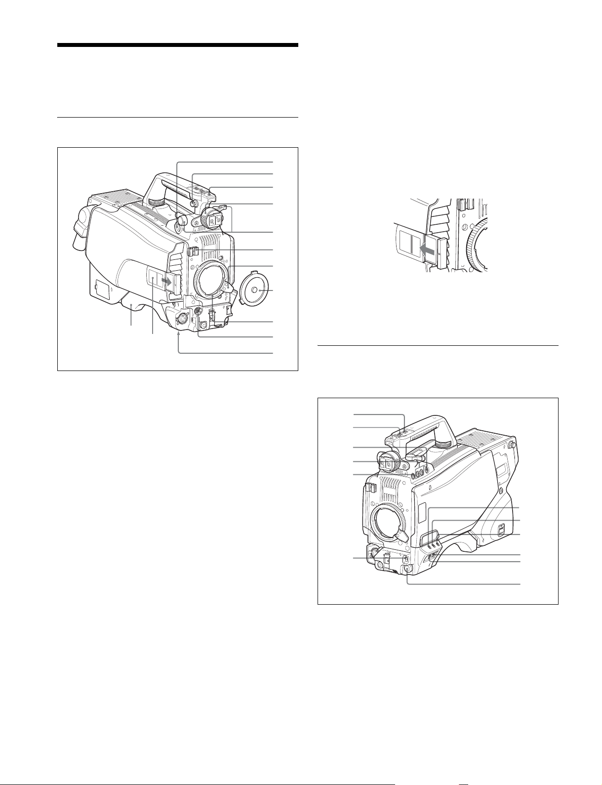
Locations and Functions of Parts
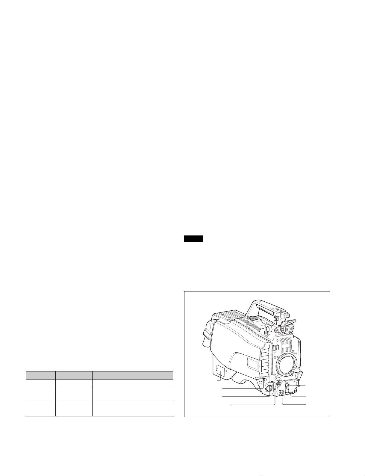
Accessory Attachments
i Lens mount
To attach a lens.
j LENS connector (12-pin)
Connect the lens cable. The camera can control the lens
functions through this cable.
k Tripod mount
Attach the VCT-14 Tripod Attachment when mounting the
camera on a tripod.
a
b
c
d
e
f
g
h
m
l
a VF (viewfinder) connector (20-pin)
Connect the cable of the viewfinder (not supplied).
b Shoulder strap fitting post
Attach one end of a shoulder strap (not supplied) to this fitting
post, and the other end to the fitting post on the other side of
the camera.
c Accessory shoe
To attach an accessory using a 1/4-inch screw.
i
j
k
l Camera number
Insert the supplied camera number label to display the camera
number.
m Shoulder pad
You can adjust the position toward the front or rear.
For details, see “Adjusting the Shoulder Pad Position” on
page 19.
Controls and Connectors
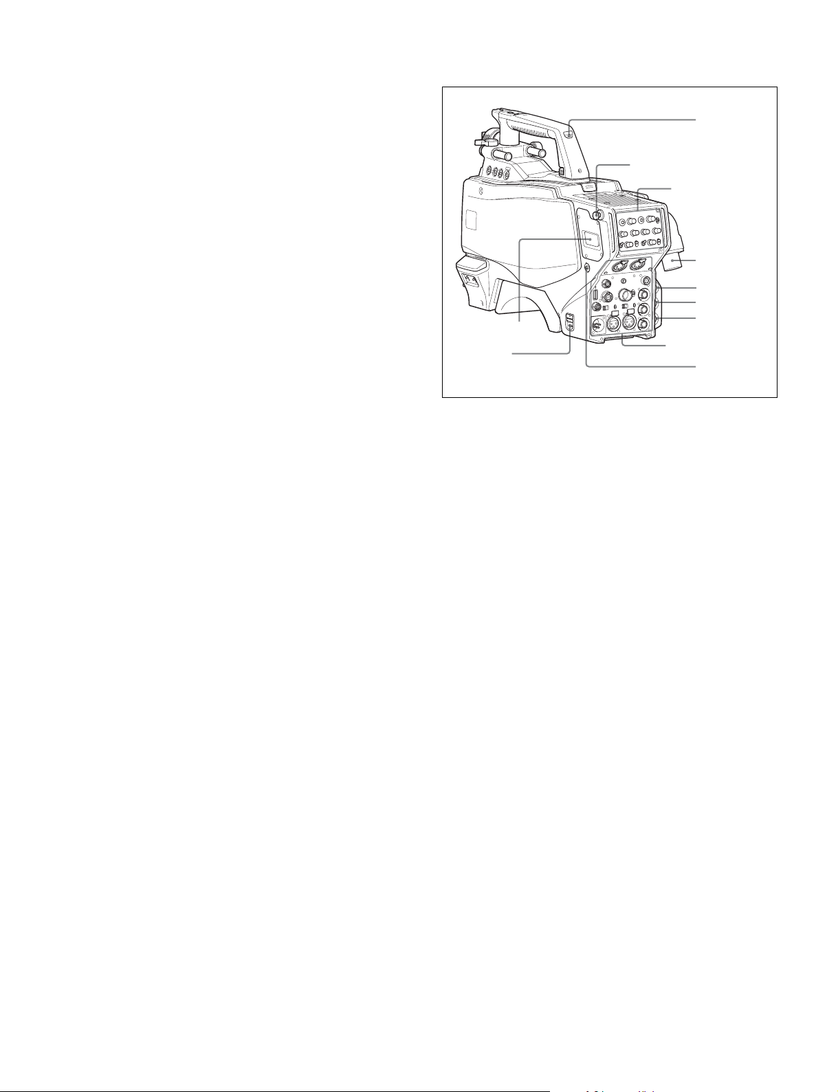
Front right
a
b
c
d
e
d Viewfinder left-right positioning ring
Locks the left-right position of the viewfinder.
Loosen this ring to adjust the viewfinder position.
e Viewfinder front-rear positioning lever and LOCK knob
Locks the front-rear position of the viewfinder.
Loosen the lever and knob to adjust the viewfinder position.
For details about adjusting the viewfinder position, see
“Attaching a Viewfinder” on page 16.
f Lens cable clamp
To secure the cable of the lens (not supplied).
g Lens fixing lever
To secure the lens in the lens mount.
h Lens mount cap
Always keep the lens mount covered with this cap when a lens
is not attached. The cover can be removed by moving the lens
fixing lever upwards.
f
a INCOM (intercom 1) button
The intercom 1 microphone is turned ON while this button is
held pressed.
You can also assign other functions to this button, using the
menu displayed on the viewfinder screen.
9
g
h
i
j
k
l
b RET 1 (return video 1) button
The return video 1 signal from the camera control unit is
monitored on the viewfinder screen while this button is
pressed. It functions the same as the RET 1 button on the side
(page 11) and on the operation panel on the rear of the
camera (page 12 (JN/SY models) or page 13 (CE/CN
models)).
You can also assign other functions to this button, using the
menu displayed on the viewfinder screen.
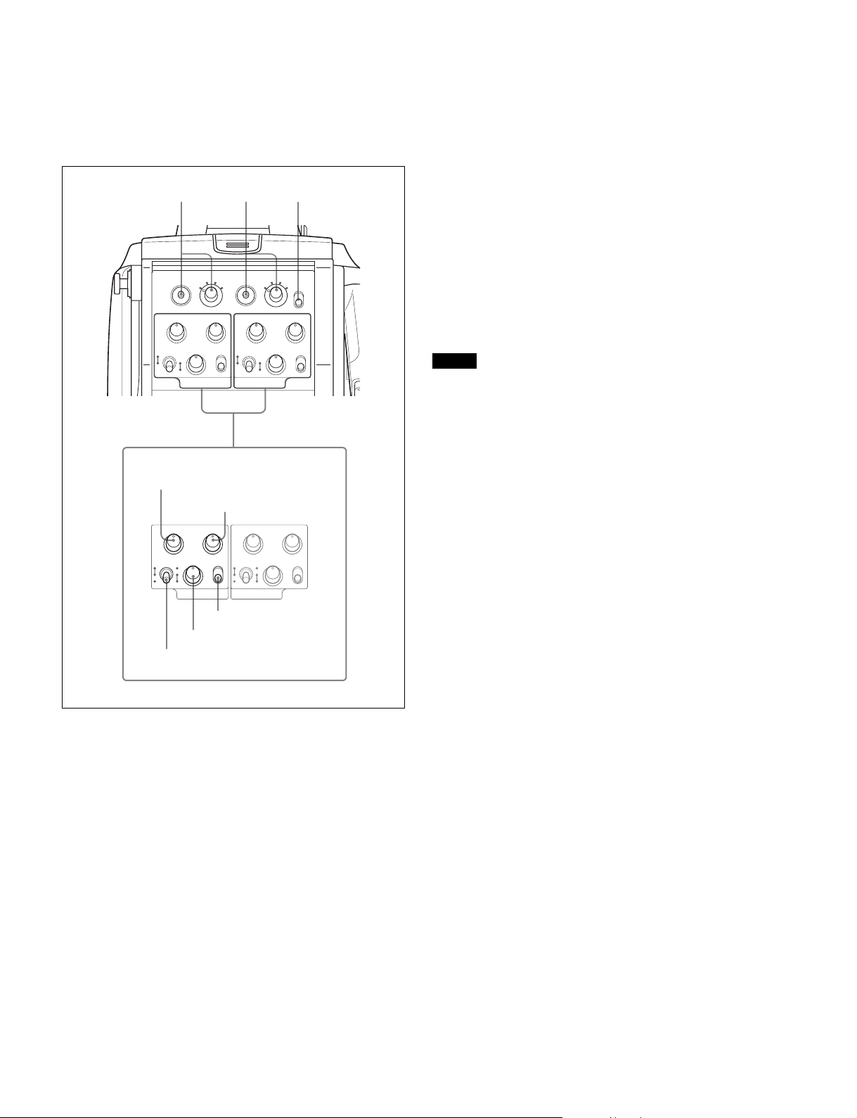
c Assignable switches
You can assign a function using the menu displayed on the
viewfinder screen.
d Filter select buttons
You can switch the built-in ND and CC (color temperature
conversion) filters by pressing the select buttons while holding
the FILTER LOCAL button depressed.
Pressing the left button selects the available ND filters (clear,
1/4ND, 1/8ND, 1/16ND,1/64ND) in sequence.
Pressing the right button selects the available CC filters (cross
1)
, 3200K, 4300K, 6300K) in sequence.
filter
1) The cross filter cannot be selected when shooting HD-HFR at 6× or
8× frame rate.
e FILTER LOCAL button
While holding this button depressed, press either of the filter
select buttons to select the built-in optical filters.
f AUTO W/B BAL (white and black balance automatic
adjustment) switch
To automatically adjust white and black balance when the
camera is used in standalone status without connecting to the
camera control unit.
WHT: Automatically adjust white balance.
BLK: Automatically adjust black balance.
g GAIN switch
To select the master gain of the video amplifier based on
lighting conditions when the camera is used in standalone
status without connecting a camera control unit.
When shipped from the factory, the values set are L = 0 dB,
M = 6 dB, and H = 12 dB.
i WHITE BAL (white balance memory selection) switch
To select the white balance adjustment method or the memory
used to store the adjusted value when the camera is used in
standalone status without connecting a camera control unit.
PRST (preset memory): White balance is adjusted to a
preset value corresponding to a color temperature of
3200K.
A or B: Selects memory A or B.
j DISPLAY switch
The functions of the DISPLAY switch are as follows:
DISPLAY: Characters and messages showing the camera
settings and operating status may be displayed on the
viewfinder screen.
OFF: Status messages will not appear on the viewfinder
screen.
MENU: Menus for camera settings will be displayed on the
viewfinder screen.
k STATUS/CANCEL switch
STATUS: When no menu is displayed on the viewfinder
screen, the status information of this camera is displayed.
CANCEL: When a menu is displayed on the viewfinder
screen, you can cancel any changed settings or return
the display to the previous menu.
l MENU SEL (menu select) knob/ENTER button (rotary
encoder)
To select settings from menus displayed on the viewfinder
screen (by turning the knob) and to confirm settings (by
pressing the button).
Note
When a camera control unit or a remote control device, such
as an MSU or RCP, is connected, the functions of 6 to 9 are
controlled from the external control device and the controls on
the camera are disabled.
Front left
h OUTPUT (output signal selection)/AUTO KNEE switch
To select the signal (color bar signal or camera’s video signal)
to be used as output to a VTR, the viewfinder or a video
monitor when the camera is used in standalone status without
connecting a camera control unit.
When the camera’s video signal is being used as output, the
auto knee function may be used.
The relationship between the switch setting and the output
signal and auto knee function is shown in the table below.
OUTPUT AUTO KNEE Function
BARS OFF Output is a color bar signal.
CAM OFF Output is the camera’s video signal.
The auto knee circuit is disabled.
CAM ON Output is the camera’s video signal.
The auto knee circuit is enabled.
a
b
c
d
a NETWORK TRUNK connector (RJ-45 8-pin)
Connects a device connected to the CCU’s NETWORK
TRUNK connector to the network.
10
e
f
g
b RET 1 (return video 1) button
The return video 1 signal from the camera control unit is
monitored on the viewfinder screen while this button is
pressed. It functions the same as the RET 1 buttons on the
handle (page 10) and on the operation panel on the rear of the
camera (page 12 (JN/SY models) or page 13 (CE/CN
models)).
You can also assign other functions to this button, using the
menu displayed on the viewfinder screen.
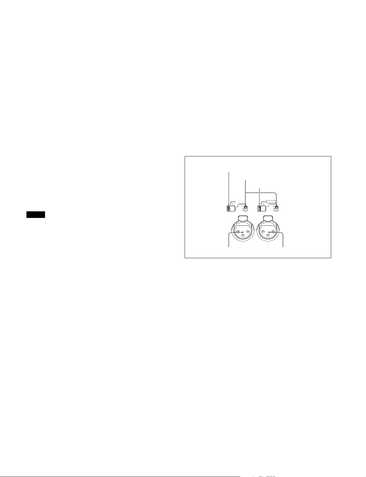
c MIC 1 IN (microphone 1 input) connector (XLR 3-pin)
Connect a microphone.
This connector and the AUDIO IN CH1 connector (page 14)
on the connector panel on the rear of the camera are
alternately activated with the CH1 audio input select switch
(page 14).
d MIC (microphone) power switch
+48V: To supply power at +48 V to the microphone connected
to the MIC 1 IN connector.
OFF: Not to supply power to the microphone connected to the
MIC 1 IN connector.
Rear
b
a
c
Shoulder strap fitting
post (page 9)
Operation panel
(page 12)
d
e
f
g
Connector panel
(page 13)
h
e SHUTTER switch
For setting the electronic shutter functions when the camera is
used in standalone status without connecting a camera control
unit.
OFF: The electronic shutter does not function.
ON: The electronic shutter is activated.
SEL: The shutter speed and shutter mode change each time
the switch is set to this position.
For details, see “Setting the Electronic Shutter” on page 22.
f INTERCOM LEVEL control
To adjust the intercom/earphone volume level.
The intercom level adjustment is enabled when the
INTERCOM 1 and 2 LEVEL/MIC switches (on the JN/SYmodel operation panel (page 12)) or the LEVEL switch (on the
CE/CN-model operation panel (page 13)) on the rear of the
camera are set to FRONT.
g RET 2 (return video 2) button
When this button is pressed, the picture on the viewfinder
screen changes to the return video signal selected with the
RET 2 select switch (page 12 (JN/SY models) or page 13 (CE/
CN models)) on the operation panel on the rear of the camera.
You can also assign other functions to this button, using the
menu displayed on the viewfinder screen.
a DC power supply out connector (2-pin)
Supplies power to an external device up to 2.5 A.
b CAMERA POWER switch
CCU: Power is supplied from the camera control unit.
EXT: Power is supplied through the DC IN connector.
c Tally lamp and switch
ON: The tally lamp lights when a tally signal is input to the
connected camera control unit or a call signal is
generated in response to pressing the CALL button.
OFF: The tally lamp is prevented from lighting.
d BPU (Baseband Processor Unit) connector (optical/
electrical multi-connector)
Connect to HDCU4300 Camera Control Unit or BPU4000/
4500 Baseband Processor Unit using an optical/electrical
multi cable.
e SDI 1 (serial digital interface 1) connector (BNC-type)
For 3G-SDI, HD-SDI or HD PROMPTER signal output.
f SDI 2 (serial digital interface 2) connector (BNC-type)
For HD-SDI signal output.
During standalone operation, also used for inputting an
HD-SDI return signal.
When RET (return) is set to 1, this is displayed in the
viewfinder.
g PROMPTER2 connector (BNC-type)
For prompter 2 signal output.
Available only when connecting a camera control unit with a
prompter 2 input connector.
During standalone operation, also used for inputting a VBS
return signal.
When RET (return) is set to 2, this is displayed in the
viewfinder.
h CALL button
When this button is pressed, the red tally lamp of the RCP1000 series Remote Control Panel or the MSU-1000 series
11
Master Setup Unit will light. Use to call the operator of the RCP
or MSU.
Operation panel
INCOM level control and the INTERCOM LEVEL control
(page 11) on the front of the camera.
INCOM (intercom) level control
Adjust the intercom audio listening level.
JN and SY models (for NTSC areas)
bc
a
PGM1 control
RET1
1
PGM1 PGM2
LEVEL
MIC
INCOM
REAR
ON
FRONT
OFF ENG
INTERCOM 1
PGM1 PGM2
2 3
4
PROD
PGM2 control
2 3
RET2
1
PGM1 PGM2
LEVEL
MIC
INCOM
REAR
ON
FRONT
OFF ENG
INTERCOM 2
PGM1 PGM2
4
d
LIGHT
PROD
Line select switch
Select the intercom line.
PROD: Producer line
ENG: Engineer line
b RET 1 (return video 1) button and select switch
Press the button to display the return video signal selected
with the switch on the viewfinder screen.
ON
OFF
c RET 2 (return video 2) button and select switch
If you use an additional return video system in addition to
return video 1, press the button to display the return video
signal selected with the switch on the viewfinder screen.
Note
The RET 1 button has priority over the RET 2 button if both
buttons are pressed.
If RET 1 and RET 2 buttons are pressed at the same time, the
two buttons function as the RET 3 button according to the
setting of the <RETURN> page in the OPERATION menu.
d LIGHT switch
Set to ON to illuminate the operation panel.
LEVEL
REAR
FRONT
MIC
ON
OFF ENG
INTERCOM 1
INCOM
PROD
LEVEL
MIC
REAR
ON
FRONT
OFF ENG
INTERCOM 2
INCOM
PROD
Line select switch
INCOM level control
LEVEL/MIC switch
a INTERCOM1 and INTERCOM2 controls and switches
There are PGM1 and 2 controls incorporated with a line select
switch, a LEVEL/MIC switch, and INCOM level control each
for intercom line 1 and 2.
PGM1 (program 1) control
Adjust the audio listening level of program 1.
PGM1 (program 2) control
Adjust the audio listening level of program 2.
LEVEL/MIC (level/microphone) switch
REAR/ON: The intercom headset microphone is turned on.
The intercom audio listening level is adjusted with the
INCOM level control.
REAR/OFF: The intercom headset microphone is turned off.
The intercom audio listening level is adjusted with the
INCOM level control.
FRONT/OFF: The intercom headset microphone is turned off.
The intercom audio listening level is adjusted with the
12
CE and CN models (for PAL areas)
OFF
+48V
MIC
FRONT MIC
PROMPTER
/GEN
LOCK
RET CTRL
AUDIO IN
CH1 CH2
TEST
OUT
SDI
MONI
DC IN 10.5-17V
LINE
OFF
+48V
MIC
AES/EBU
LINE
EARPHONE
REMOTE
DC OUT
CRANETRACKER
234
RET1
ENG PROD
MIC
PROD
LINE1
OFF
ENG
a
PROD control
ENG control
ENG PROD
MIC
PROD
LINE1
OFF
ENG
MIC LINE1 switch
MIC LINE2 switch
2 3
1
4
INTERCOM 1
PGM1 control
INTERCOM 1
TRACKER control
2 3
RET2
1
PGM1 PGM2
MIC
TRACKER
PROD
LINE2
OFF
ENG
INTERCOM 2
PGM2 control
PGM1 PGM2
MIC
TRACKER
PROD
LINE2
OFF
ENG
INTERCOM 2
LEVEL switch
MIC LINE2 (intercom microphone line 2) switch
Select the talk line for intercom 2.
PROD: To talk over the producer line
OFF: To turn off the headset microphone for intercom line 2
ENG: To talk over the engineer line
LEVEL switch
REAR: The intercom audio listening level is adjusted with the
LIGHT
4
ON
OFF
controls on this panel.
FRT: The intercom audio listening level is adjusted with the
INTERCOM LEVEL control (page 11) on the front of the
camera.
LEVEL
REAR
FRT
b RET 1 (return video 1) button and select switch
The return video signal selected with the switch is displayed
on the viewfinder screen while the button is pressed.
c RET 2 (return video 2) button and select switch
When other return video systems are used in addition to return
video 1, you can monitor the signal selected with the switch on
the viewfinder screen while pressing the button.
Note
The RET 1 button has priority over the RET 2 button if both
buttons are pressed.
If RET 1 and RET 2 buttons are pressed at the same time, the
LEVEL
REAR
FRT
two buttons function as the RET 3 button according to the
setting of the <RETURN> page in the OPERATION menu.
d LIGHT switch
Set to ON to illuminate the operation panel.
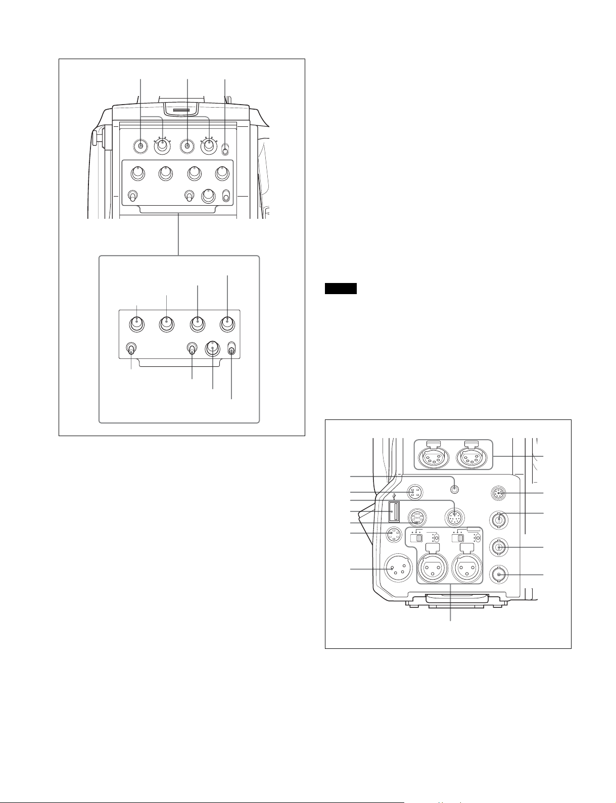
Connector panel
a INTERCOM1 and INTERCOM2 controls and switches
The reception level controls are common to intercom 1 and
intercom 2. The talk lines can be set independently for
intercom 1 and intercom 2.
ENG (engineer line) control:
Adjust the intercom audio listening level of the engineer line.
PROD (producer line) control
Adjust the intercom audio listening level of the producer line.
PGM1 (program 1) control
Adjust the audio listening level of program 1.
PGM2 (program 2) control
Adjust the audio listening level of program 2.
TRACKER control
Adjust the intercom audio listening level at the TRACKER
connector (page 14) on the connector panel when using the
connector for intercom.
MIC LINE1 (intercom microphone line 1) switch
Select the talk line for intercom 1.
PROD: To talk over the producer line
OFF: To turn off the headset microphone for intercom line 1
ENG: To talk over the engineer line
h
a
b
c
d
i
j
e
f
k
g
l
m
a EARPHONE jack (stereo minijack)
For connecting an earphone or headset to hear the intercom
audio.
b DC OUT (DC power supply output) connector (4-pin)
To supply power to devices such as a wireless receiver
(optional) (max. 0.5 A).
13
c CRANE connector (12-pin)
For external interface, such as viewfinder and external data.
d USB connector (for connecting a USB drive)
Connect a USB drive to save or load the settings data file.
For details, see “Using a USB Drive” on page 68.
e TRACKER connector (10-pin)
For external interface, such as intercom and tally.
f RET CTRL (return control) connector (6-pin)
For connection to a CAC-6 Return Video Selector.
g DC IN (DC power supply input) connector (XLR 4-pin)
Used for connection to the AC-DN10 AC Adaptor to supply
power to the camera.
h INTERCOM1 and 2 (intercom 1 and 2) connectors (XLR
5-pin)
Used for input and output of intercom audio signals if an XLR
5-pin headset is connected.
The INTERCOM 1 connector can be used for communication
over the engineer line even when the power is off, as long as
the power LED is lit in red.
i REMOTE connector (8-pin)
For connection to an RCP-1000/1500-series Remote Control
Panel, or MSU-1000/1500 Master Setup Unit.
Note
When the camera is connected to a camera control unit, do not
connect any remote control device, such as RCP and MSU, to
this connector.
k TEST OUT connector (BNC-type)
To output the analog signal.
This also supplies the VBS signal, an HD signal nearly equal
to the signal output from the VF connector, an HD-SYNC
signal, or an SD-SYNC signal depending on which of these
you have selected on the menu.
For details about signal settings, see “Setting the Camera
Outputs” on page 27.
l SDI-MONI (serial digital interface) connector
(BNC-type)
For HD-SDI or SD-SDI signal output.
For details about signal settings, see “Setting the Camera
Outputs” on page 27.
m AUDIO IN CH1 and CH2 connectors (XLR 3-pin) and
switches
Connect audio signals. An input select switch and microphone
power switch are provided for each channel.
CH1 audio input select switch
Microphone power switches
CH2 audio input select switch
LINE
FRONT MIC
MIC
48V
OFF
AUDIO IN
CH 1
LINE
AES/EBU
MIC
48V
OFF
CH 2
j PROMPTER/GENLOCK (prompter signal output/
external genlock signal input) connector (BNC-type)
The PROMPTER function is available only when a camera
control unit is connected. The GENLOCK IN function and RET
IN function are available when a camera control unit is not
connected.
GENLOCK IN: For input of an external genlock signal (VBS or
3-level sync) during standalone operation.
RET IN: For input of the return video signal during standalone
operation.
The connector accepts analog HD signals only. SDI
signals cannot be input. Supply a signal of 1080i (720P
cannot be input).
The signal supplied to this connector cannot be fed as
RET OUT from the TEST OUT or SDI OUT connector.
This is displayed in the viewfinder regardless of which
RET is selected. CHARACTER will not be overlapped for
the displayed RET 3 signal.
PROMPTER: For output of the prompter 1 signal (valid only
when a camera control unit is connected). When a
camera control unit having two prompter inputs is
connected, the signal of input 1 is output from this
connector.
AUDIO IN CH2 connectorAUDIO IN CH1 connector
CH1 audio input select switch
Set to the appropriate position according to the equipment
connected to the AUDIO IN CH1 connector.
LINE: When a line-level (0 dBu) signal source is connected
FRONT MIC: When using the microphone connected to the
MIC 1 IN connector
MIC: When an external microphone is connected
CH2 audio input select switch
Set to the appropriate position according to the equipment
connected to the AUDIO IN CH2 connector.
LINE: When a line-level (0 dBu) signal source is connected
AES/EBU: When a digital audio signal is connected (The
signal must be in synchronization with the camera
output.)
MIC: When an external microphone is connected
Microphone power switches
When a microphone is connected to the corresponding AUDIO
IN connector, set whether or not to supply a power to the
microphone.
+48V: To supply a power of +48 V.
OFF: Not to supply power.
(No function has been assigned to the lowermost position. No
power is supplied to the microphone.)
14
Note
To supply +12 V power, contact a Sony sales representative
or Sony service representative.
Preparations
Attaching a Lens
For information on handling lenses, refer to the lens’ operation
manual.
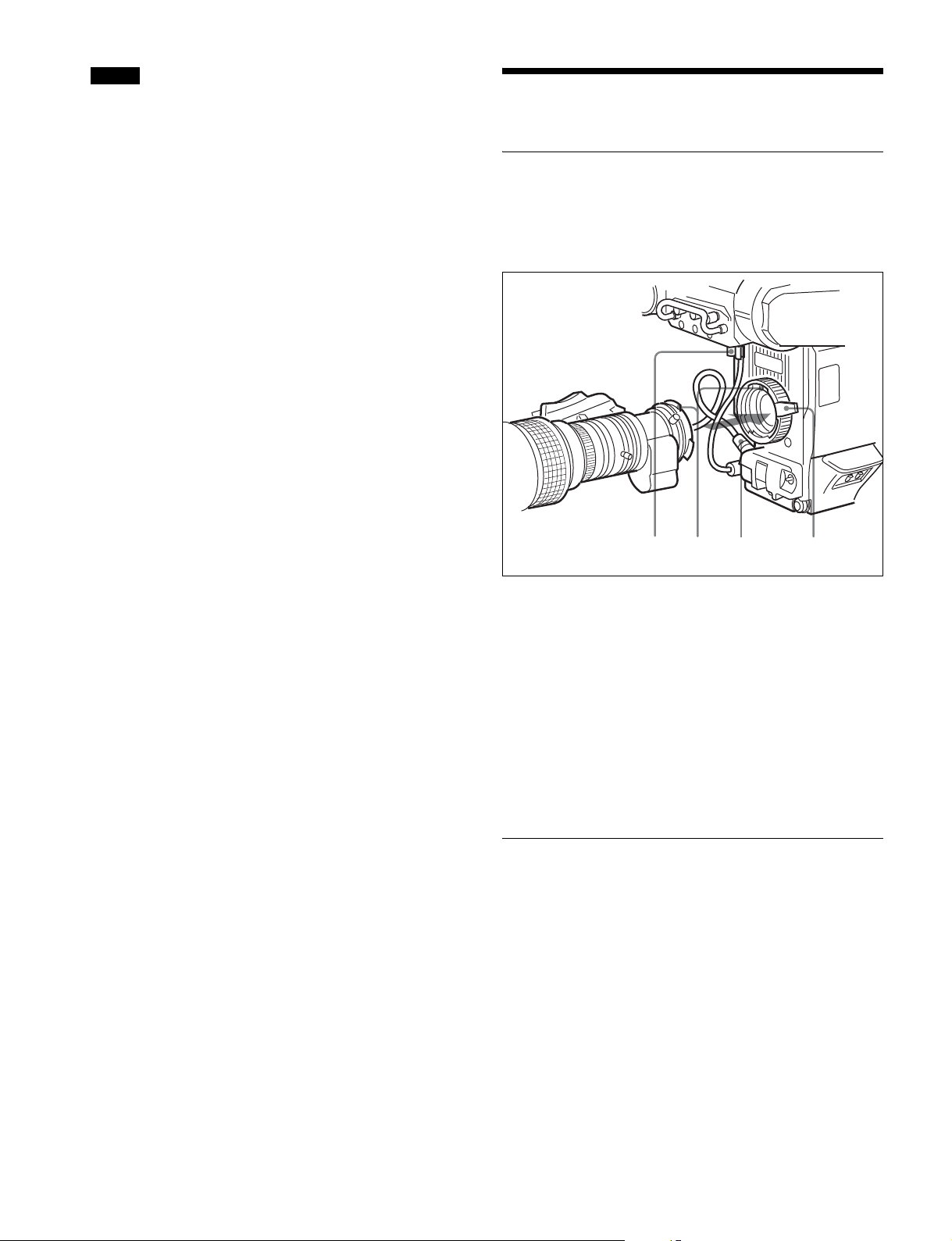
Attachment procedure
1,3425
1 Push the lens fixing lever upwards and remove the
lens mount cap from the lens mount.
2 Align the lens’ alignment pin with the notch in the
upper part of the lens mount and insert the lens into
the mount.
3 While supporting the lens, push the lens fixing lever
downwards to secure the lens.
4 Connect the lens cable to the LENS connector.
5 Secure the lens cable with the cable clamp.
Adjusting the Flange Focal Length
Adjustment of the flange focal length (the distance between
the lens mount attachment plane and the imaging plane) is
necessary in the following situations:
• The first time a lens is attached
• When changing lenses
• If the focus is not sharp at both telephoto and wide angle
when zooming
The flange focal length can be more precisely adjusted by
using the focus assist indicators.
For details about focus assist indicators, see “Displaying the
focus assist indicators” on page 24.
15
Note
The various parts of the lens used in adjusting the flange focal
length are in different positions on different lenses. Refer to
the operation manual for the particular lens.
Adjustment procedure
1 Set the iris control to manual, and open the iris fully.
2 Place a flange focal length adjustment chart
approximately 3 meters from the camera and adjust
the lighting to get an appropriate video output level.
3 Loosen the Ff (flange focal length) ring lock screw.
4 With either manual or power zoom, set the zoom ring
to telephoto.
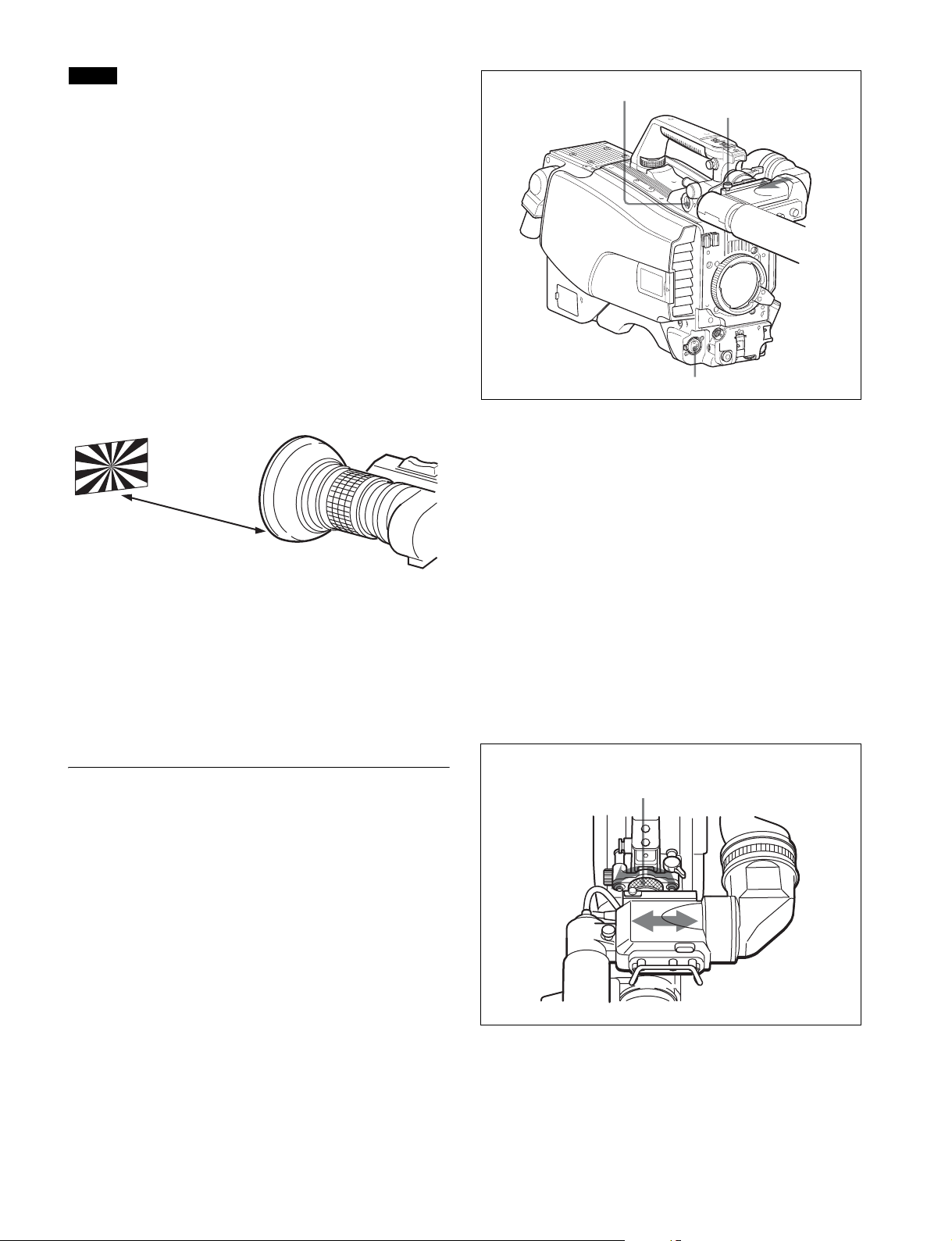
VF connector
Viewfinder stopper
5 Aim at the flange focal length adjustment chart and
turn the focus ring to focus the image.
About 3 meters (10 ft)
6 Set the zoom ring to wide angle.
7 Turn the Ff ring to bring the chart into focus. Take
care not to move the distance ring.
8 Repeat steps 4 through 7 until the image is in focus at
both telephoto and wide angle.
9 Tighten the Ff ring lock screw.
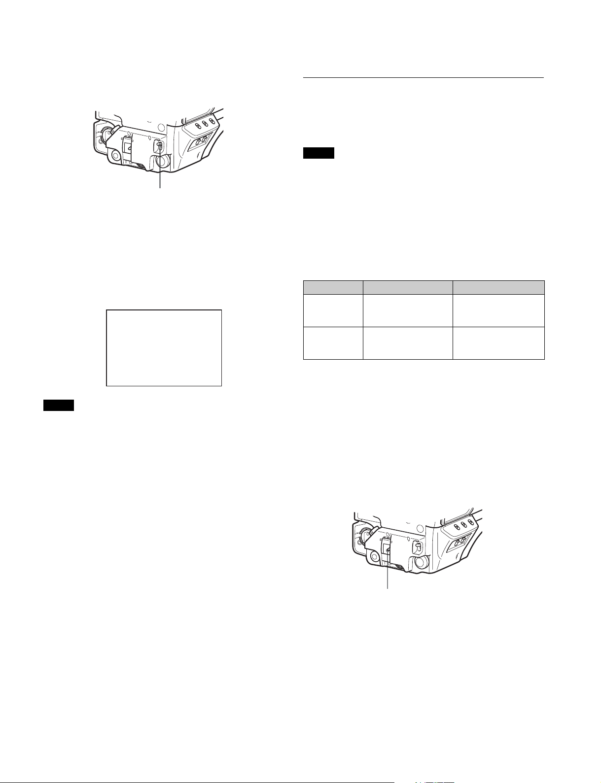
Attaching a Viewfinder
WARNING
When the viewfinder is attached, do not leave the camera with
the eyepiece facing the sun. Direct sunlight can enter through
the eyepiece, be focused in the viewfinder and cause fire.
MIC 1 IN connector
1 Slide the viewfinder in the direction of the arrow.
The viewfinder stopper automatically pops down.
2 Set the viewfinder left-right position, then tighten the
left-right positioning ring (see “To adjust the position
to the left or right” below).
3 Connect the viewfinder cable to the VF connector of
the camera.
4 Connect the microphone cable to the MIC 1 IN
connector of the camera.
Adjusting the viewfinder position
The viewfinder position may be adjusted towards the front and
rear and to the left and right to make it easy to see into it.
To adjust the position to the left or right
Viewfinder left-right
positioning ring
Attaching a viewfinder
The instructions are made using the HDVF-20A/200
viewfinder as an example.
For details about the viewfinder, refer to the operation manual
of the viewfinder.
1 Loosen the viewfinder left-right positioning ring.
2 Slide the viewfinder left or right to move it into a good
viewing position.
16
3 Tighten the viewfinder left-right positioning ring.
Attaching procedure of the BKW-401
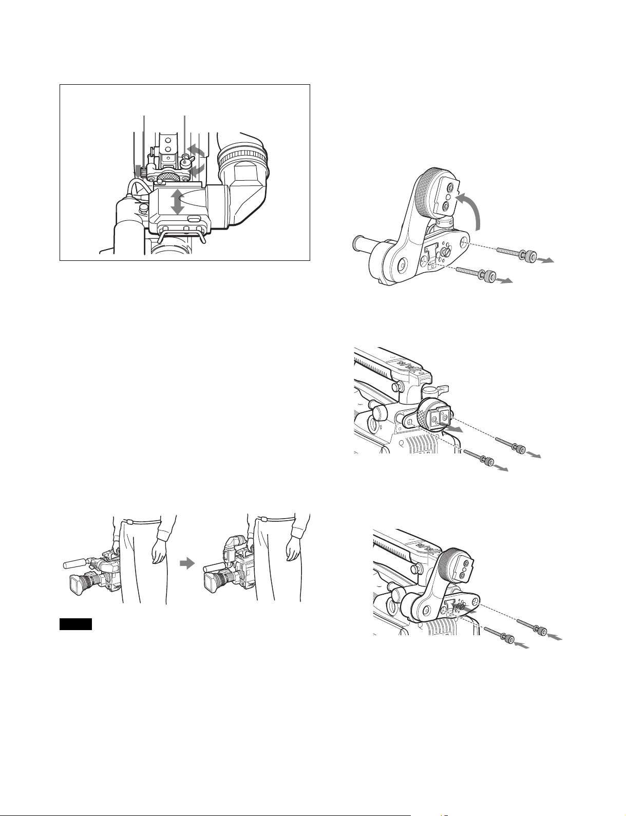
To adjust the position forward or backward
Viewfinder front-rear
LOCK knob
positioning lever
1 Loosen the viewfinder front-rear positioning lever
and LOCK knob.
2 Slide the viewfinder towards the front or rear of the
camera to move it into a good viewing position.
3 Tighten the viewfinder front-rear positioning lever
and LOCK knob.
1 Turn the arm of the rotation mechanism assembly of
the BKW-401 in the direction of the arrow in the
following illustration.
Next, using a hexagonal wrench 3 mm across flats,
remove the bolts (M4×8) together with the washers, to
separate the rotation mechanism assembly from the
viewfinder front-back positioning mechanism
assembly.
2 In the same manner as step 1, remove the viewfinder
shoe of the camera from the front-rear positioning
mechanism assembly.
Detaching the viewfinder
Loosen the viewfinder left-right positioning ring, pull the
viewfinder stopper, then pull out the viewfinder by sliding it in
the direction opposite to that when attached.
Keeping the viewfinder from hitting your leg
(using BKW-401)
To keep the viewfinder from bumping your leg when carrying
the camera, install the BKW-401 Viewfinder Rotation Bracket
(optional) and rotate the viewfinder upwards.
Note
Lock the viewfinder in a slightly forward position before
rotating it upwards. If the viewfinder is in its rearmost position,
the arm of the viewfinder rotation bracket will strike the camera
handle.
3 Using the two bolts (M4×8) and the washers removed
from the camera in step 2, attach the rotation
mechanism assembly of the BKW-401 to the camera.
Bolt
M4×8
17
4 Adjust the front-rear position so that the camera
handle does not interfere when you rotate the
BKW-401 arm upwards.
Not interfering with handle
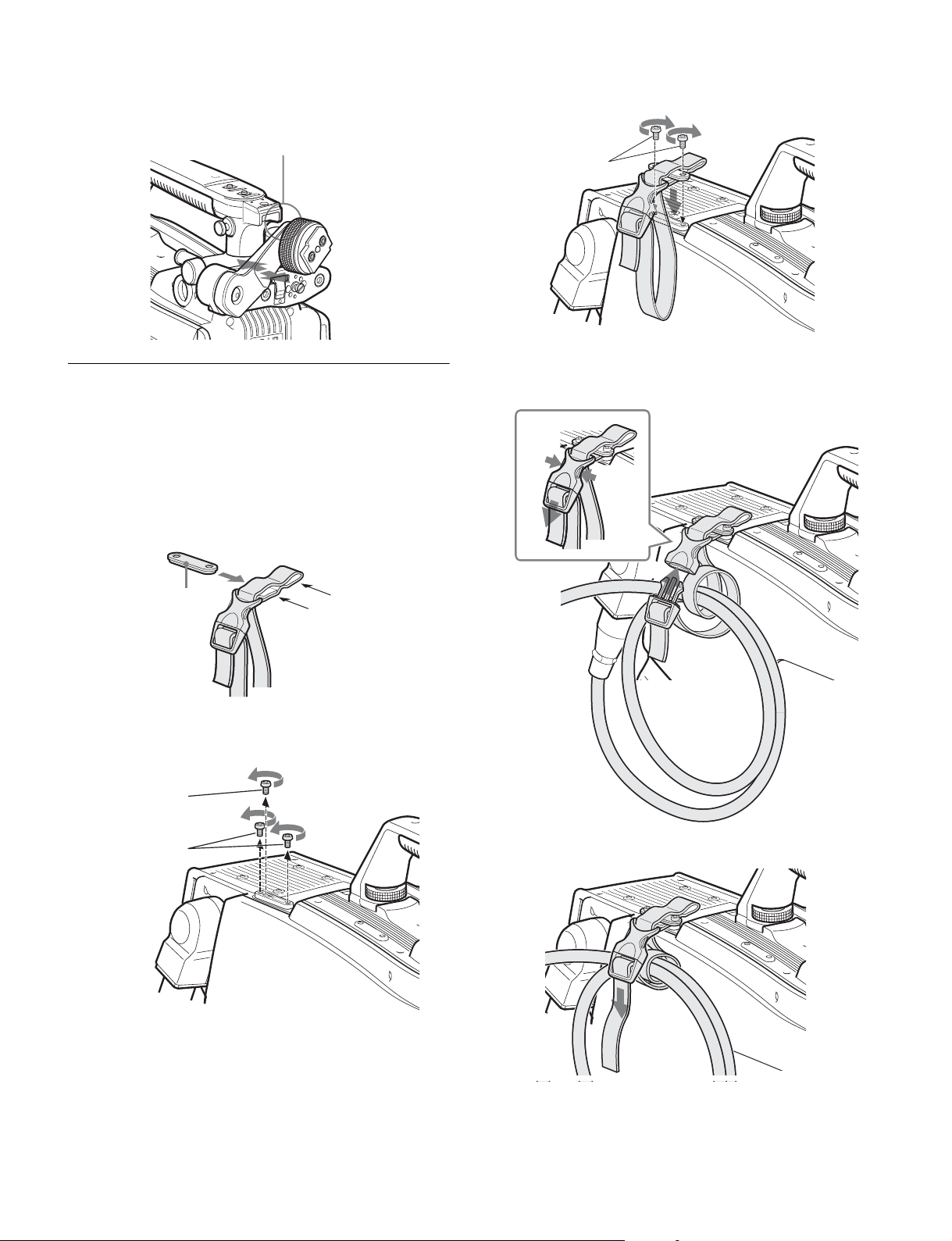
Attaching the Cable Clamp Belt
(Supplied)
3 Secure the cable clamp belt to the camera, using the
two supplied +B3×8 screws.
Screws (+B3×8)
4 1 Release the buckle, 2 bundle the cable with the
3 then lock the buckle again.
belt,
You can secure the optical/electrical multi cable, connected to
the BPU connector, to the side of the camera by attaching the
supplied cable clamp belt.
1 Insert the belt bracket into hole A or B of the cable
clamp belt.
Belt bracket
B
A
2 Remove two +B3×5 screws and a hidden screw
shown in the figure below from the camera.
Hidden screw
Screws (+B3×5)
1
3
2
Optical/electrical
multi cable
5 Adjust the length by pulling down the end of the belt.
18
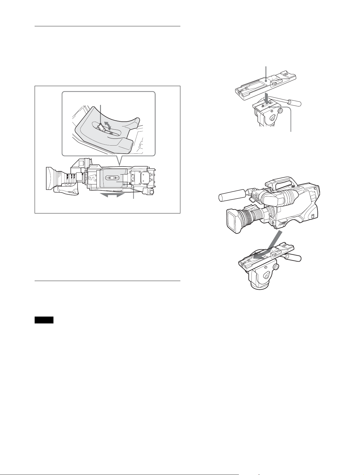
Adjusting the Shoulder Pad Position
You can shift the shoulder pad from its center position (factory
setting) backward by up to 10 mm (13/32 inch) or forward by
up to 25 mm (1 inch). This adjustment helps you get the best
balance for shooting with the camera on your shoulder.
Adjustment procedure
Shoulder pad lock lever
1,3
Attachment procedure
1 Attach the tripod attachment to the tripod and secure
it with the screw.
Tripod attachment
Tripod plate
2 Place the camera on the tripod attachment, and slide
forward it along the groove of the tripod attachment
until it clicks.
Bottom of the camera
2
Shoulder pad
1 Raise the lever in the center of the shoulder pad to
unlock the shoulder pad.
2 Slide the shoulder pad backward or forward until it is
in the most convenient position.
3 Move the lever down to lock the shoulder pad in the
selected position.
Mounting the Camera to a Tripod
Mount the camera to a tripod using a VCT-14 Tripod
Attachment.
Notes
• Select an appropriate hole from among those at the bottom
of the tripod attachment considering the balance of the
weight of the camera and the tripod attachment. If an
inappropriate hole is selected, the camera may fall over and
may cause injury or damage.
• Check that the size of the selected hole matches that of the
screw of the tripod. If they do not match, the tripod
attachment cannot be attached to the tripod securely.
3 Make sure that the camera is securely attached by
moving it back and forth.
19
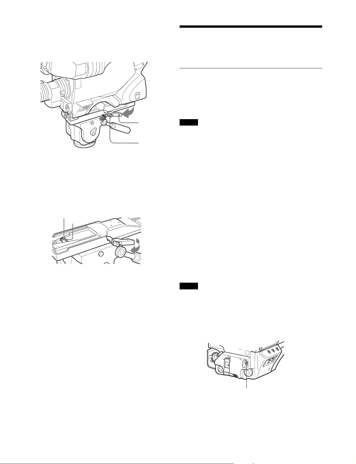
Removing the camera from the tripod
attachment
Hold down the red button and pull the lever in the direction of
the arrow.
Adjustments and Settings for Shooting
Adjusting the Black Balance and White
Balance
In order to maintain high picture quality, it is necessary to set
the black balance and white balance appropriately for the
conditions.
Lever
Red button
If the pin of the tripod attachment does not return to
its original position
After removing the camera, if the pin of the tripod attachment
does not return to its original position, hold down the red
button and move the lever in the direction of the arrow to return
the pin to its original position. It is not possible to mount a
camera with the pin not seated.
Original position
Pin
Note
When a camera control unit or a remote control device, such
as the MSU or RCP series, is connected, control is performed
from the RCP/MSU, and the switches on the camera are
disabled.
Black balance adjustment
The black balance needs adjustment in situations like the
following:
• The first time the camera is used
• When the camera is used after a long period of disuse
• When the surrounding temperature changes greatly
• When the gain value is changed using the setup menus
Normally, there is no need to adjust the black balance every
time the camera is turned on.
White balance adjustment
Always readjust the white balance when lighting conditions
change.
About the viewfinder screen
After the process of adjusting the black balance or white
balance begins, messages about the progress and results of
the adjustment will be displayed on the viewfinder screen.
Note
Adjusted values set through automatic adjustment, and other
settings, are stored in the camera’s memory and preserved
even when the camera power is turned off.
Adjusting the black balance
Push the AUTO W/B BAL switch toward BLK (downward).
AUTO W/B BAL switch
Automatic adjustment of black balance begins.
In automatic adjustment of black balance, both the black set
and black balance are adjusted.
20
During adjustment, a message like the one in the figure below
HD
MULTI FORMA
T SERIES
will be displayed on the viewfinder screen.
ABB:EXECUTING
When the adjustment process is completed, the message
“ABB : OK” will be displayed. The adjusted value is
automatically stored in memory.
To select the CC (color temperature conversion) filter
Press the CC filter select button while holding the FILTER
LOCAL button depressed.
Each press of the select button switches the available CC
filters (cross filter
1)
, 3200K, 4300K, 6300K) in sequence.
Notes
• During black balance adjustment, the iris will be
automatically closed.
• During black balance adjustment, the gain switching circuit
will work automatically, and the viewfinder screen will flicker
several times. This is not a malfunction.
When automatic black balance adjustment fails
If the automatic black balance adjustment process does not
end successfully, the error message “ABB : NG” will be
displayed on the viewfinder screen for approximately three
seconds.
If this error message is displayed, try black balance
adjustment again.
If the error message continues to be displayed after several
attempts, the camera requires internal inspection.
About black balance memory
The black balance values stored in memory will be preserved
even when the camera power is turned off.
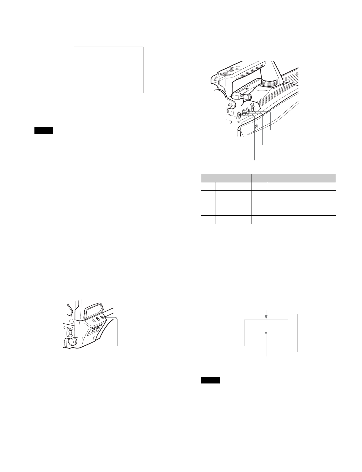
Adjusting the white balance
1 Set the WHITE BAL switch to A or B.
CC filter select button
ND filter select button
FILTER LOCAL button
ND filter Color temperature conversion filter
1 Clear A Cross filter
2 1/4ND B 3200K (clear)
3 1/8ND C 4300K
4 1/16ND D 6300K
5 1/64ND – –
1) The cross filter cannot be selected when shooting HD-HFR at
6× or 8× frame rate.
1)
3 Place a white pattern in the same lighting conditions
as the subject, and zoom in on it so that a white area
is obtained in the screen to satisfy the positional and
quantitative requirements illustrated below.
A white object (white cloth, a white wall, etc.) near the
subject may be used in place of a white pattern.
A rectangle centered in the screen.
The length of the sides must be at least 70% of the
height and width of the screen.
WHITE BAL switch
2 Select the filter setting according to the lighting
conditions.
To select the ND filter
Press the ND filter select button while holding the FILTER
LOCAL button depressed.
Each press of the select button switches the available ND
filters (clear, 1/4ND, 1/8ND, 1/16ND,1/64ND) in sequence.
Within this rectangle, there must be an area of
white greater than 10% of the entire screen.
Note
Be careful not to have any spots of high illumination in the
rectangle.
4 Adjust the lens iris opening.
With a manually adjusted lens: Set the opening to an
appropriate value.
21
With a lens which has automatic iris control: Set the
lens’ automatic/manual iris control switch to
automatic.
memory. Each memory can store up to five adjusted values,
for a total of 10.
5 Push the AUTO W/B BAL switch to WHT (up).
AUTO W/B BAL switch
White balance automatic adjustment begins.
During adjustment, the message “AWB : EXECUTING”
will be displayed on the viewfinder screen.
A message like the one in the figure below will be
displayed, and the adjustment process will complete. The
adjusted value will be automatically stored in the memory
(A or B) selected in step 1.
AWB:OK
Setting the Electronic Shutter
This section explains the different modes which can be used
for the electronic shutter and gives the procedures for setting
the shutter mode and shutter speed.
Note
When a camera control unit or a remote control device, such
as the MSU or RCP series, is connected, control is performed
from the RCP/MSU, and the switches on the camera are
disabled.
About the shutter modes
The shutter modes that can be used with the electronic shutter
of the camera and the shutter speeds that may be selected are
as follows:
Shutter modes and speeds
Shutter mode Shutter speeds
Standard 1/100, 1/125, 1/250,
ECS
(Extended
Clear Scan)
* The values in the table are those with 59.94P. With other formats,
the available values are different.
1/500, 1/1000, 1/2000
(seconds)
Continuously variable in
the range of 59.96 Hz to
4600 Hz
*
Usage
Use to obtain clear
images of quickly
moving subjects
Use to obtain images on
video monitors without
horizontal striping
Note
When using a zoom lens with automatic iris control capability,
hunting1) may occur. Adjust the lens’ iris gain control (labeled
IG, IS, S, etc.).
1) Hunting: The automatic iris responds over and over, and the image
repeatedly darkens and lightens.
For more information, refer to the lens’ operation manual.
When automatic white balance adjustment fails
If the white balance adjustment process does not end
successfully, the error message “AWB : NG” will be displayed
on the viewfinder screen for approximately three seconds.
If this error message is displayed, try white balance
adjustment again.
If the error message continues to be displayed after several
attempts, the camera requires internal inspection.
When there is no time to adjust the white balance
Set the WHITE BAL switch to PRST. The white balance will be
set automatically according to the filter settings.
About white balance memory
The white balance values stored in memory will be preserved
even when the camera power is turned off.
There are two white balance memories, A and B. When the
AUTO W/B BAL switch is pushed to the WHT side, the white
balance will be adjusted automatically according to the filter
settings. The adjusted value will be stored in the selected
Selecting the shutter mode and speed
The shutter mode, and the shutter speed in standard mode,
are set using the SHUTTER switch.
Setting the shutter mode, and shutter speed in
Standard mode
1 Push the SHUTTER switch from the ON position to the
SEL position.
SHUTTER switch
The current shutter setting will be displayed on the
viewfinder screen for about three seconds.
Example: “SHUTTER: 1/250”
2 Push the SHUTTER switch to the SEL position again
before the display disappears. Repeat this action until
the desired mode or speed is displayed.
When all modes and speeds are displayed, they will be
displayed in the following order:
22
Loading...