


 Loading...
HCD-TB10
SERVICE MANUAL
Ver 1.0 2002. 04
This set is the tuner, deck, CD and amplifier section in CHC-TB10.
AEP Model
UK Model
E Model
CD |
Model Name Using Similar Mechanism |
NEW |
|
|
|
||
CD Mechanism Type |
CDM55C-K6A |
||
SECTION |
|||
|
|
||
|
Optical Pick-up Block Type |
KSM-213DCP |
|
|
|
|
|
TAPE DECK |
Model Name Using Similar Mechanism |
NEW |
|
SECTION |
|
|
|
Tape Transport Mechanism Type |
CMAL1Z222A |
||
|
|||
|
|
|
SPECIFICATIONS
Amplifier section
European models
DIN power output (Rated):40 + 40 watts
(6 ohms at 1 kHz, DIN) Continuous RMS power output (Reference):
50 + 50 watts
(6 ohms at 1 kHz, 10% THD)
Music power output (Reference):
100 + 100 watts
(6 ohms at 1 kHz, 10% THD)
Other models
Measured at AC 120/220/240 V, 50/60 Hz: DIN power output (Rated):40 + 40 watts
(6 ohms at 1 kHz, DIN) Continuous RMS power output (Reference):
50 + 50 watts
(6 ohms at 1 kHz, 10% THD)
Inputs
MD IN (phono jacks): voltage 450 mV, impedance 47 kilohms
Outputs
PHONES (stereo minijack):
accepts headphones of 8 ohms or more.
SPEAKER: Accepts impedance of 6 to 16 ohms.
CD player section
System |
Compact disc and digital |
|
audio system |
Laser |
Semiconductor laser |
|
(λ=780 nm) |
|
Emission duration: |
|
continuous |
9-873-944-01 Sony Corporation
Frequency response 2 Hz – 20 kHz (±0.5 dB) CD DIGITAL OUT
(Square optical connector jack, rear panel)
Wavelength |
660 nm |
Tape deck section |
|
Recording system |
4-track 2-channel stereo |
Frequency response |
50 – 13,000 Hz (±3 dB), |
|
using Sony TYPE I |
Tuner section |
cassettes |
|
|
FM stereo, FM/AM superheterodyne tuner |
|
FM tuner section |
|
Tuning range |
87.5 – 108.0 MHz |
|
(50 kHz step) |
Antenna |
FM lead antenna |
Antenna terminals |
75 ohms unbalanced |
Intermediate frequency |
10.7 MHz |
AM tuner section |
|
Tuning range |
|
European models: |
531 – 1,602 kHz |
|
(with the interval set at |
|
9 kHz) |
Pan-American models: |
531 – 1,710 kHz |
|
(with the interval set at |
|
9 kHz) |
530 – 1,710 kHz (with the interval set at 10 kHz)
Other models: |
531 – 1,602 kHz |
|
(with the interval set at |
|
9 kHz) |
|
530 – 1,710 kHz |
|
(with the interval set at |
|
10 kHz) |
Antenna |
AM loop antenna |
|
External antenna terminals |
Intermediate frequency |
450 kHz |
General |
|
Power requirements |
|
European models: |
230 V AC, 50/60 Hz |
Mexican model: |
120 V AC, 60 Hz |
Other models: |
120 V, 220 V, 230 – |
|
240 V AC, 50/60 Hz |
|
Adjustable with voltage |
|
selector |
Power consumption |
|
European models: |
100 watts |
|
0.5 watts (at the Power |
|
Saving Mode) |
Other models: |
100 watts |
Dimensions (w/h/d) incl. projecting parts and controls Amplifier/Tuner/Tape/CD section:
Approx. 215 × 285 × 334 mm
Mass
Amplifier/Tuner/Tape/CD section: Approx. 6.5 kg
Design and specifications are subject to change without notice.
COMPACT HiFi COMPONENT SYSTEM
2002D1600-1 Home Audio Company
© 2002.04 |
Published by Sony Engineering Corporation |
TABLE OF CONTENTS
6.DIAGRAMS ······································································ 19 6-1. Circuit Boards Location ············································· 19 6-2. Block Diagrams ·························································· 21 6-3. Printed Wiring Board – MAIN Section – ·················· 23 6-4. Schematic Diagram – MAIN Section (1/4) – ············ 24 6-5. Schematic Diagram – MAIN Section (2/4) – ············ 25 6-6. Schematic Diagram – MAIN Section (3/4) – ············ 26 6-7. Schematic Diagram – MAIN Section (4/4) – ············ 27 6-8. Schematic Diagram – PANEL Section – ··················· 28 6-9. Printed Wiring Board – PANEL Section – ················ 29 6-10. Printed Wiring Board – LCD Section – ··················· 30 6-11. Schematic Diagram – AMP/POWER Section – ········ 31 6-12. Printed Wiring Board – AMP Section – ···················· 32 6-13. Printed Wiring Board – POWER Section – ·············· 33 6-14. Schematic Diagram – CD Section – ························· 34 6-15. Printed Wiring Board – CD Section – ······················· 35 6-16. Printed Wiring Board – MOTOR Section – ·············· 36 6-17. IC Pin Function Description ······································ 39
7.EXPLODED VIEWS ······················································ 41 7-1. Side Panel, Back Panel Section ·································· 41 7-2. Front Panel Section ···················································· 42 7-3. Chassis Section ·························································· 43 7-4. CD Mechanism Deck Section (CDM55C-K6A) ······· 44
8.ELECTRICAL PARTS LIST ······································· 45
HCD-TB10
SECTION 1
SERVICING NOTES
NOTES ON HANDLING THE OPTICAL PICK-UP
BLOCK OR BASE UNIT
The laser diode in the optical pick-up block may suffer electrostatic break-down because of the potential difference generated by the charged electrostatic load, etc. on clothing and the human body.
During repair, pay attention to electrostatic break-down and also use the procedure in the printed matter which is included in the repair parts.
The flexible board is easily damaged and should be handled with care.
NOTES ON LASER DIODE EMISSION CHECK
The laser beam on this model is concentrated so as to be focused on the disc reflective surface by the objective lens in the optical pickup block. Therefore, when checking the laser diode emission, observe from more than 30 cm away from the objective lens.
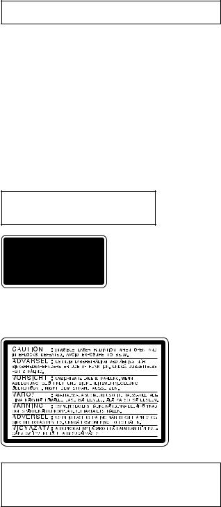
Laser component in this product is capable of emitting radiation exceeding the limit for Class 1.
This appliance is classified as a CLASS 1 LASER product. The CLASS 1 LASER PRODUCT MARKING is located on the rear exterior.
This caution label is located inside the unit.
CAUTION
Use of controls or adjustments or performance of procedures other than those specified herein may result in hazardous radiation exposure.
Notes on chip component replacement
•Never reuse a disconnected chip component.
•Notice that the minus side of a tantalum capacitor may be damaged by heat.
Flexible Circuit Board Repairing
•Keep the temperature of soldering iron around 270˚C during repairing.
•Do not touch the soldering iron on the same conductor of the circuit board (within 3 times).
•Be careful not to apply force on the conductor when soldering or unsoldering.
SAFETY-RELATED COMPONENT WARNING!!
COMPONENTS IDENTIFIED BY MARK 0OR DOTTED LINEWITH MARK 0 ON THE SCHEMATIC DIAGRAMS AND IN THE PARTS
LIST ARE CRITICAL TO SAFE OPERATION. REPLACE THESE COMPONENTS WITH SONY PARTS WHOSE PART NUMBERS APPEAR AS SHOWN IN THIS MANUAL OR IN SUPPLEMENTS PUBLISHED BY SONY.
3
HCD-TB10
Service position of the TAPE cassette mechanism deck
MAIN board
Jig cord : J-2501-082-A
CN404
TC Deck section
4

A – G
BASS wa (18)
CD disc tray qk (8) CD SYNC wj (16) CD NX wl (9)
DIMMER 2 (22) DISPLAY 3 (14, 21) Display window 5 EDIT wg (17)
ENTER qd (8, 10, 11, 17, 20, 27) FUNCTION qg (9, 10, 15, 16,
24)
GROOVE ws (18)
BUTTON DESCRIPTIONS
?/1 1
+/M L 7 x wh
l –/m 6
Z ql (8)
SECTION 2 GENERAL
M – Z
MD 9 (24)
MUSIC MENU wd (19) PHONES jack w;
PLAY MODE/TUNING MODE qf (9, 11, 26)
REC PAUSE/START wk (16) Remote sensor q; REPEAT/FM MODE qh (9, 13,
26)
SURROUND wf (18) Tape deck lid 4 (15) TAPE nN qs (15, 16) TREBLE qj (19) TUNER/BAND e; (11, 13)
TUNER MEMORY/DIRECTION qa (11, 15)
VOL 8
A – G
CD ql (9) CLEAR wd (10)
CLOCK/TIMER SELECT 2 (21, 25)
CLOCK/TIMER SET 7 (8, 17, 20)
DISPLAY qh (14, 21) EFFECT ON/OFF qf (19)
ENTER 7 (8, 10, 11, 17, 20, 27) GROOVE qd (18)
BUTTON DESCRIPTIONS
@/1 4 N 9 x 9 X 9
m/M wa
./ ws
HCD-TB10
This section is extracted from instruction manual.
M – Z
MD 0 (24)
MUSIC MENU +/– qg (19) PLAY MODE 5 (9, 26) PRESET –/+ ws
REPEAT 6 (9)
SLEEP 1 (20) SURROUND qs (18) TAPE qa (15) TONE qk (18)
TUNER/BAND w; (11, 13) TUNER MEMORY 8 (11) TUNING –/+ wa (11)
VOL +/– qj
5

HCD-TB10
Setting the clock
1 Turn on the system.
2 Press CLOCK/TIMER SET on the remote.
“CLOCK” appears.
3 Press . or > on the remote to set the hour.
4 Press ENTER.
The minute indication flashes.
5 Press . or > on the remote to set the minute.
6 Press ENTER.
The clock starts working.
Tip
If you make a mistake while setting the clock, press x, then start over from step 2.
To adjust the clock
1Press CLOCK/TIMER SET on the remote.
2Press . or > on the remote to select “CLOCK”, then press ENTER.
3Do the same procedures as step 3 to 6 above.
Note
You cannot set the clock in the Power Saving Mode.
Loading a CD
1 Press Z.
The disc tray opens.
2 Place a CD with the label side up on the
disc tray.
When you play a CD single (8 cm CD), place it on the inner circle of the tray.
3 Press Z again to close the disc tray.
6
HCD-TB10
SECTION 3
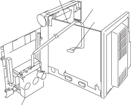
DISASSEMBLY
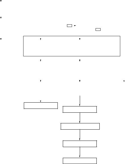
• The equipment can be removed using the following procedure.
|
|
|
|
|
|
|
|
|
|
|
|
|
|
|
|
|
|
|
|
|
|
|
|
|
SET |
|
|
|
|
|
|
|
|
|
|
|
|
|
|
|
|
|
|
|
|
|
|
|
|
|
|
|
|
|
|
|
|
|
|
|
|
|
|
|
|
|
|
|
|
|
|
|
|
|
|
|
|
|
|
|
|
|
|
|
|
|
|
|
|
|
|
|
|
|
|
|
|
|
|
|
|
|
|
|
|
|
|
|
|
|
|
|
||
|
|
|
|
|
|
|
|
|
|
|
|
|
|
|
|
|
|
|
|
|
|
|
|
|
SIDE PANEL |
|
|
|
|
|
|
|
|
|
|
|
|
|
|
|
|
|
|
||
|
|
|
|
|
|
|
|
|
|
|
|
|
|
|
|
|
|
|
|
|
|
|
|
|
|
|
|
|
|
|
|
|
|
|
|
|
|
|
|
|
|
|
|
||
|
|
|
|
|
|
|
|
|
|
|
|
|
|
|
|
|
|
|
|
|
|
|
|
|
TOP PANEL |
• |
The dotted square with arrow ( |
|
|
|
) prompts you to move to the next |
||||||||||||||
|
|
|
|
|
|
|
|
|||||||||||||||
|
|
|
|
|
|
|
job when all of the works within the dotted square ( |
)are completed. |
||||||||||||||
|
|
|
|
|
|
|
|
|
|
|
|
|
|
|
|
|
|
|||||
|
|
|
|
|
|
|
|
|
|
|
|
|
|
|
|
|
|
|
|
|
|
|
|
|
|
|
|
|
|
|
|
|
|
|
|
|
|
|
|
|
|
|
|
|
|
CASSETTE MECHANISM |
|
|
FRONT PANEL |
|
|
|
|
SUB TRANSFORMER BOARD, |
|
|
||||||||||||
(CMAL1Z222A) |
|
|
|
|
|
|
|
|
BACK PANEL |
|
|
|
|
|||||||||
|
|
|
|
|
|
|
|
|
|
|
|
|||||||||||
|
|
|
|
|
|
|
|
|
|
|
|
|
|
|
|
|
|
|
|
|
|
|
|
|
|
|
|
|
|
|
|
|
|
|
|
|
|
|
|
|
|
|
|
|
|
|
|
|
|
|
|
|
|
|
|
|
|
|
|
|
|
|
|
|
|
|
||
|
|
|
|
|
|
|
|
|
|
|
|
|
|
|
|
|
|
|
|
|
|
|
|
|
|
|
|
|
|
|
|
|
|
|
|
|
|
|
|
|
|
|
|
|
|
|
|
|
|
|
|
|
|
H/P BOARD, |
|
|
|
MAIN BOARD |
|
|
|
|
|
|||||
|
|
|
|
|
|
|
|
PANEL BOARD |
|
|
|
|
|
|
|
|
|
|
|
|
||
|
|
|
|
|
|
|
|
|
|
|
|
|
|
|
|
|
|
|
||||
|
|
|
|
|
|
|
|
|
|
|
|
|
|
|
|
|
|
|
|
|
|
|
|
|
|
|
|
|
|
|
|
|
|
|
|
|
|
|
|
|
|
|
|
|
|
|
|
|
|
|
|
|
|
|
|
|
|
|
|
|
|
|
|
|
|
|
|
|
|
|
|
|
|
|
|
|
|
|
|
|
|
|
|
|
|
|
|
|
|
|
|
|
|
|
|
|
|
|
LCD BOARD, |
|
|
CDM BOARD, |
|
POWER TRANSFORMER, |
||||||||||
|
|
|
|
|
|
|
BACK LIGHT BOARD |
|
CD MECHANISM |
|
P-AMP BOARD |
|||||||||||
|
|
|
|
|
|
|
|
|
|
|
|
DECK (CDM55C-K6A) |
|
|
|
|
||||||
|
|
|
|
|
|
|
|
|
|
|
|
|
|
|
|
|||||||
|
|
|
|
|
|
|
|
|
|
|
|
|
|
|
|
|
|
|
|
|
|
|
|
|
|
|
|
|
|
|
|
|
|
|
|
|
|
|
|
|
|
|
|
|
|
VOL BOARD
CAM (CDM55)
MOTOR (TRAY) BOARD
HOLDER ASSY
MOTOR BOARD
Note : Follow the disassembly procedure in the numerical order given.
7

HCD-TB10
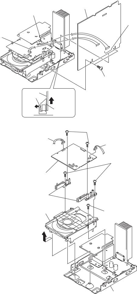
3-1. Side Panel
6 side panel (L) (Remove in the direction of the arrow.)
5four screws (CASE 3 TP2)
4two screws (+BVTP 3 × 10)
3 side panel (R) (Remove in the direction of the arrow.)
1two screws (+BVTP 3 × 10)
2 four screws 
 (CASE 3 TP2)
3-2. Top Panel
Note: Attach it so that it pressed down the MAIN board.
2 screw
(+BVTP 2.6 × 8)
5 connector
3 top panel
(Remove in the direction of the arrow.)
6 flat cable (9 core) (CN404)
1 screw
(+BVTP 2.6 × 8)
4 screw
(+BVTP 2.6 × 8)
8
HCD-TB10
3-3. Cassette Mechanism (CMAL1Z222A)
6 flat cable (9 core)
2 two screws |
|
(+BVTP 2.6 × 8) |
|
|
7 cassette mechanism deck |
|
(CMAL1Z222A) |
|
1 two screws |
4 screw |
(+BVTP 2.6 × 8) |
(+PTPWH 2.6 × 5) |
|
5 shield tc |
3 screw |
(Cassette mechanism) |
(+PTPWH 2.6 × 5) |
3-4. Front Panel
1 screw
(+BVTP 2.6 × 8)
2 flat cable (30 core)
(CN403)
6 front panel
4 connector (CN304)
3 flat cable (15 core) (CN733)
5 three screws (+BVTP 3 × 10)
9

HCD-TB10
3-5. H/P Board, PANEL Board
qf flat cable (39 core) (CN607)
0 two claws
4 CD Lid
5 spring (CD) |
3 two screws |
|
(+PTPWH 2.6 × 5) |
|
qa two claws |
3-6. LCD Board, BACK LIGHT Board
6 Remove solderings.
4 sub panel
2 two claws
3 two claws
front panel assy
9 three claws
qs PANEL board
(Remove in the direction of the arrow.)
qd connector
6 two screws
(CN611) ×
(+BVTP 2.6 8)
7 three screws (+BVTP 2.6 × 8)
8 ten screws (+BVTP 2.6 × 8)
1 two screws
(+BVTP 2.6 × 8)
2 H/P board
0 liquid crystal display panel
5 two screws (+BVTP 2.6 × 8)
8 LCD board
9 BACK LIGHT board
7two screws (+BVTP 2.6 × 8)
1 two screws (+BVTP 2.6 × 8)
10
HCD-TB10
3-7. VOL Board
Note: daring reassembling
when flange.
spring
sub panel
flange
6 VOL board
4 spring
5 shuttle
3 flange
2 nut
1 knob (vol)
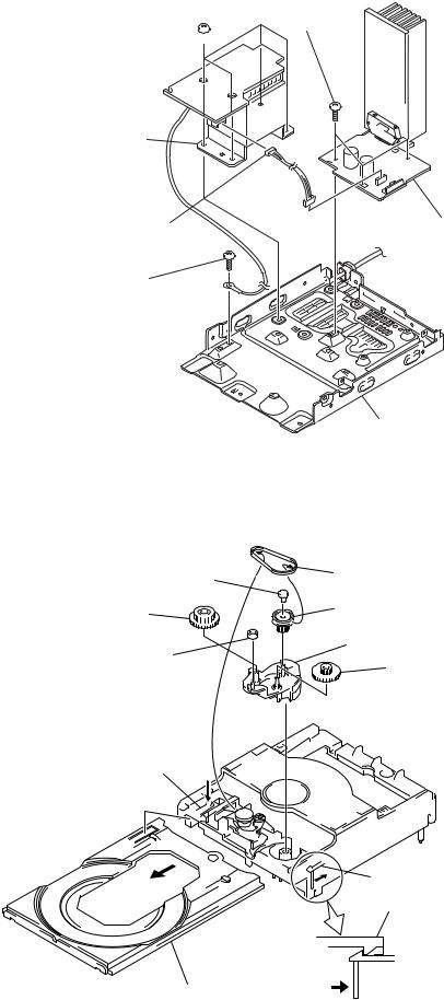
3-8. SUB TRANSFORMER Board, Back Panel
8 SUB TRANSFORMER board |
|
|
9 back panel |
|
|
1 connector |
4 six screws |
|
(CN903) |
||
(+BVTT 3 × 8) |
||
2 connector |
|
|
(CN907) |
|
|
7 two screws |
|
|
(+BVTT 3 × 8) |
|
|
3 connector |
|
|
(CN905) |
|
|
6 screw |
|
|
(+BVTT 3 × 8) |
|
|
|
5 two screws |
|
|
(+BVTT 3 × 10) |
11
HCD-TB10
3-9. MAIN Board
5 MAIN Board
3 connector (CN906)
4 connector (CN402)
2connector (CN734)
1 two screws (+BVTP 3 × 10)
MAIN board
CN501
(Pull out MAIN board.)
CN402
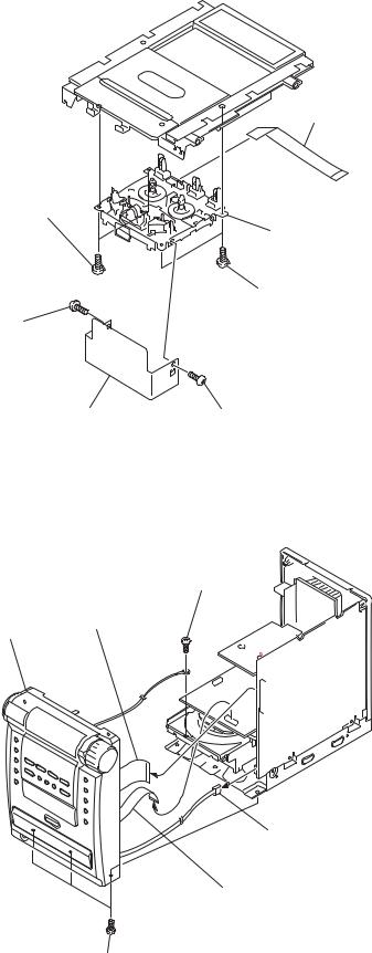
3-10. CDM Board, CD Mechanism Deck (CDM55C-K6A)
4 connector (CN735)
6 CDM board
8 pwb, holder
2 CD mechanism deck (CDM55C-K6A) (Remove in the direction of the arrow.)
5two screws (+BVTP 2.6 × 8)
3 connector (CN732)
7 two screws (+BVTT 2.6 × 8)
1screw (+BVTT 3 × 8)
chassis section
12
HCD-TB10
3-11. Power Trans Former, P-AMP Board
5 three screws (+BVTP 2.6 × 8)
3four screws 
 (+BVTT 4 × 6)
4 power transformer
1 connector |
6 P-AMP board |
|
|
(CN906) |
|
2 screw |
|
(+BVTP 2.6 × 8) |
|
chassis
3-12. Cam (CDM55)
7 bushing |
4 |
6 belt (CDM55) |
|
||
|
|
|
|
|
5 |
0 gear (B) |
|
8 pulley (LDG) |
|
|
|
9 roller |
|
qa cam (CDM55) |
|
|
|
|
|
qs gear (A) |
2 Push the claw in the direction of arrow C. C
A |
|
1 Pull out the tray in the arrow direction A, |
|
B |
and release the lock while pressing |
||
|
|||
|
|
this claw in the arrow direction B. |
3 Pull out the tray. |
B |
Release |
|
|
13
HCD-TB10
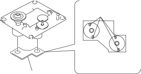
3-13. MOTOR (TRAY) Board
1 two screws (M 2.6)
2 MOTOR (TRAY) board
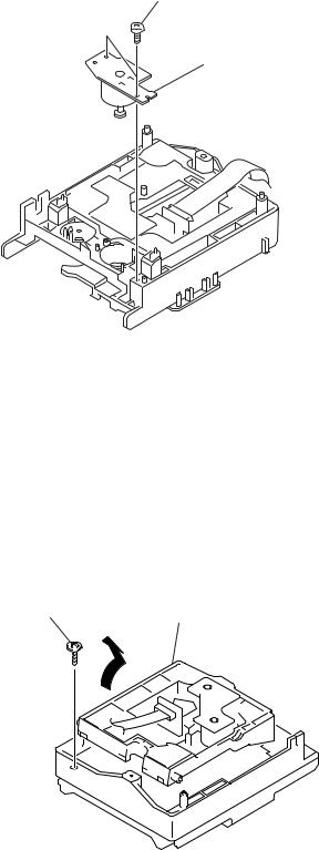
3-14. Holder Assy
1 floating screw
(PTPWH M2.6)
2 Remove the Holder (BU) assy in the direction of arrow A.
A
14
HCD-TB10
3-15. MOTOR Board
1 Remove the four solders.
M101
M102
2 MOTOR board
15
HCD-TB10
SECTION 4
TEST MODE
[Change-over of AMTuner Step between 9 kHz and 10 kHz]
•A step of AM channels can be changed over between 9 kHz and 10 kHz. (EXCEPT AEP, UK model)
Procedure:
1.Press the ?/1 button to turn the set on.
2.Select the function “TUNER”, and press the ENTER button to select the band “AM”.
3.Press the ?/1 button to turn the set off.
4.Press two buttons ENTER and ?/1 simultaneously, and the LCD changes to “AM 9 k STEP” or “AM 10 k STEP”, and thus the channel step is changed over.
[CD Ship Mode ]
•This mode moves the pickup to the position durable to vibration. Use this mode when returning the set to the customer after
repair.
Procedure:
1.Press the ?/1 button to turn the set on.
2.Press the NX button and the ?/1 button simultaneously.
3.The “STANDBY” display blinks instantaneously, then “LOCK” is displayed and the CD ship mode is set.
[CD Lock Mode ]
• This mode locks the tray and a CD in the set even after poweroff.
Procedure:
1.Press the ?/1 button to turn the set on.
2.Set a CD in the set.
3.Press two buttons x and Z simultaneously for five seconds.
4.The message “LOCKED” is displayed and the tray is locked.
5.After the power-off, the tray is still locked.
6.To unlock the tray , press two buttons x and Z simultaneously for five seconds.
7.The message “UNLOCKED” is displayed and the tray is unlocked.
[Cold Reset]
•The cold reset clears all data including preset data stored in the RAM to initial conditions. Execute this mode when returning
the set to the customer.
Procedure:
1. Press three buttons x , ENTER and ?/1 simultaneously. 2. The LCD displays “C RESET” and the set is reset.
[Version and Destination Display Mode]
• The version or destination is displayed.
Procedure:
1.Turn the set off.
2.To enter the test mode, press three buttons DIMMER , x and ENTER simultaneously.
3.The model and the destination is displayed.
4.Press the DISPLAY button.
5.The version is displayed.
6.Press the DISPLAY button again.
7.The date of this version is displayed.
8.To exit from this mode, press three buttons DIMMER , x and ENTER simultaneously.
[Panel Test Mode]
•All LCD segments and LEDs are tested.
•Keyboard check.
Procedure:
1.Press the ?/1 button to turn the set on.
2.To enter the test mode, press three buttons DISPLAY , x and ENTER simultaneously.
3.All segments and LEDs are turned on.
4.Press the DISPLAY and FUNCTION buttons simultaneously, and the key number check mode is activated.
5.The message “KEY0 0 0” is displayed.
Each time a button is pressed, the key code number is displayed.
6.Press the DISPLAY and FUNCTION buttons simultaneously, and the key count mode is activated.
7.The message “CNT 0 1” is displayed.
Each time a button is pressed, “CNT 0 1” value increased. However, once a button is pressed, it is no longer taken into account.
8.Press the DISPLAY and FUNCTION buttons simultaneously, and the volume control detect mode is activated.
9.The message “VOL FLAT” is displayed.
“VOL UP” is displayed if rotating VOL knob upward, or “VOL DOWN” is displayed if rotating dowanward.
10.Press the DISPLAY and FUNCTION buttons simultaneously, and the headphone detect mode is activated.
11.The message “HP OFF” is displayed when a headphone jack is not inserted.
“HP ON ” is displayed when a headphone jack is inserted.
12.To exit from the panel test mode after the headphone detect mode, press three buttons DISPLAY , x and ENTER simultaneously.
[MC Test Mode]
• This mode is used to test the function of the equalizer.
Procedure:
1.Press the ?/1 button to turn the set on.
2.To enter the test mode, press three buttons REC PAUSE/START , x and ENTER simultaneously.
3.Rotate the VOL knob upward. The volume is set to “VOL MAX”.
4.Rotate the VOL knob downward. The volume is set to “VOL MIN”.
5.Press the MUSIC MENU button.
The function of the equalizer is set to “GEQ FLAT”.
4.Press the BASS button.
The function of the equalizer is set to “GEQ MIN”.
5.Press the TREBLE button.
The function of the equalizer is set to “GEQ MAX”.
6.To exit from this mode, press the ?/1 button.
The LCD displayed “C RESET”, then the set is reset and turned off.
[CD Service Mode]
• This mode can run the CD sled motor freely. Use this mode, for instance, when cleaning the pickup.
Procedure:
1.Press the ?/1 button to turn the set on.
2.Select the function “CD”.
3.To enter the test mode, press three buttons CD SYNC , x and ENTER simultaneously.
4.The message “CD S” is displayed and the CD service mode is selected.
5.With the CD in stop status, press the +/M button to move the pickup to outside track and “CD S –F” is displayed, or press the –/m button to inside track and “CD S –R” is displayed.
6.To exit from this mode, press the ?/1 button.
The pick up moves to most inside track and the power is turned off.
16
HCD-TB10
SECTION 5
ELECTRICAL ADJUSTMENTS
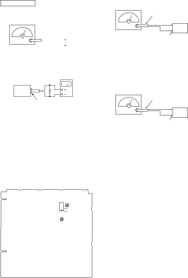
TUNER SECTION
AM IF Adjustment
AM RF Signal generator
|
|
|
|
|
set |
|
|
|
|
|
|
|
|
|
|
|
|
|
|
|
|
|
|
|
|
|
|
30% amplitude |
|
|
|
|
||
|
|
|
|
|||
modulation by |
AM ANTENNA terminal |
|||||
400Hz signal |
(JK101) |
|||||
output level : as low as possible |
|
|
|
|
||
FM Tuned Level Adjustment
FM RF Signal generator
75 Ω coaxial
Carrier frequency : 98 MHz
Modulation |
: AUDIO 1 kHz, 75 kHz |
|
deviation (100%) |
Output level |
: 30 dB (at 75 Ω open) |
set
FM ANTENNA terminal (JK101)
Procedure:
1.Supply a 98 MHz signal at 28 dB from theANTENNA terminal.
2.Tune the set to 98 MHz.
3.Adjust SFR101 to the point (moment) when the TUNED indicator will change from going off to going on.
level meter
16 Ω
set
headphones jack (JK302)
Procedure:
1.Set the frequency of the AM RF signal generator to 1000 kHz (at 10 kHz step) or 999 kHz (at 9 kHz step).
2.Tune the set to AM 1000 kHz (at 10 kHz step) or 999 kHz (at 9 kHz step).
3.Adjust IFT101 so that the reading on level meter becomes in maximum.
Adjustment Location: MAIN board
[MAIN BOARD] Component side
T101: NULL
IC101
 IFT101: AM IF
Adjustment Location: MAIN board
Null Adjustment
FM RF Signal generator
75 Ω coaxial
Carrier frequency : 98 MHz
Modulation |
: AUDIO 1 kHz, 75 kHz |
|
deviation (100%) |
Output level |
: 60 dB (at 75 Ω open) |
set
FM ANTENNA terminal (JK101)
Procedure:
1.Supply a 98 MHz signal at 60 dB from theANTENNA terminal.
2.Tune the set to 98 MHz.
3.Measure voltage between pin 22 and pin 3 of IC 101. Adjust
T101 until the voltage becomes 0 V.
Adjustment Location: MAIN board
SFR101:
FM TUNED LEVEL
17
Loading...