


HCDS-880
Table of contents
 Loading...
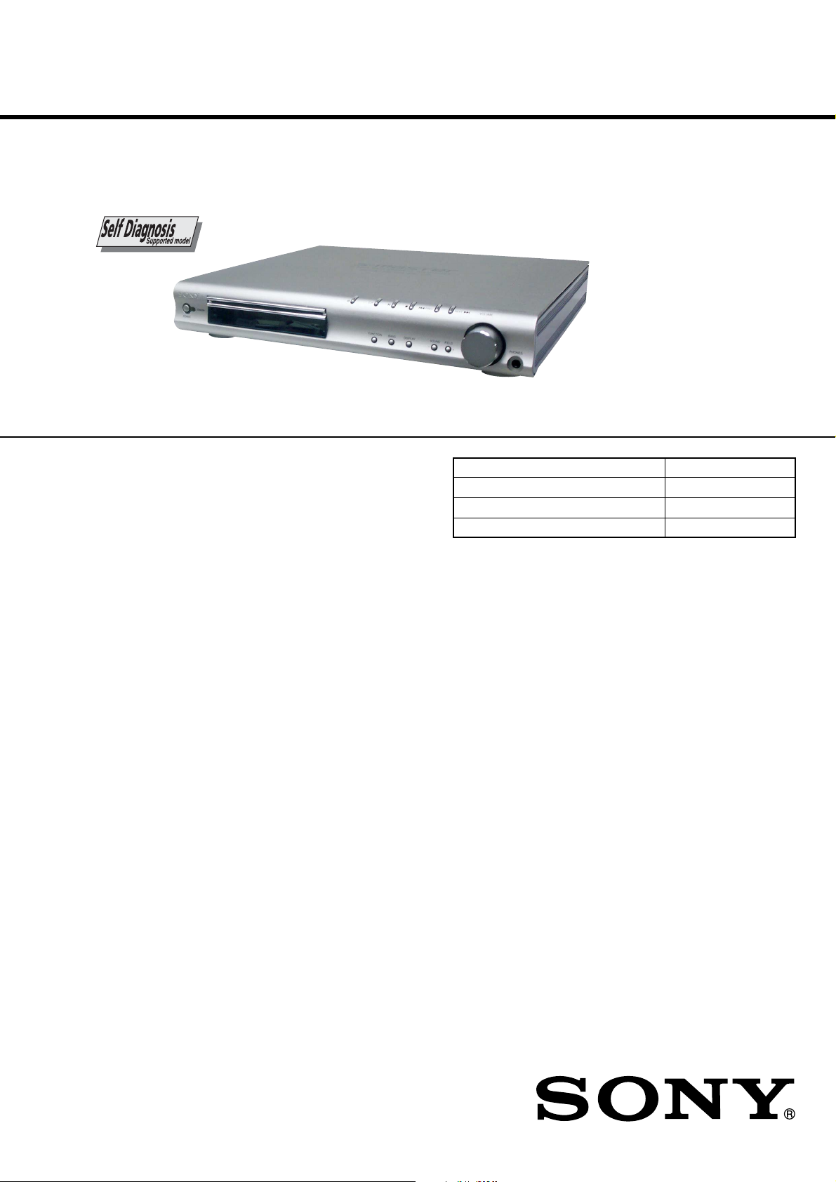
HCD-S550/S880
SERVICE MANUAL
Ver 1.6 2004.03
Photo: HCD-S550
HCD-S550/S880 is the amplifier, DVD/CD
player and tuner section in DAV-S550/S880.
SPECIFICATIONS
Amplifier section
S550:
Stereo mode 80 W + 80 W (4 ohms at 1 kHz, THD 10 %)
Surround mode Front: 80 W + 80 W
Center*: 80 W
Rear*: 80 W + 80 W (4 ohms at 1 kHz, THD 10 %)
Subwoofer*: 100 W (3 ohms at 100 Hz, THD 10 %)
S880:
Stereo mode 100 W + 100 W (3 ohms at 1 kHz, THD 10 %)
Surround mode Front: 100 W + 100 W
Center*: 100 W
Rear*: 100 W + 100 W (3 ohms at 1 kHz, THD 10 %)
Subwoofer*: 100 W (3 ohms at 100 Hz, THD 10 %)
* Depending on the sound field settings and the source, there may be no sound output.
AEP Model
UK Model
E Model
Australian Model
Chinese Model
Model Name Using Similar Mechanism NEW
Mechanism Type CDM72B-DVBU12
Base Unit Name DVBU12
Optical Traverse Unit Name DBU-1
Inputs (Analog) VIDEO 1, 2:
Sensitivity: 150 mV
Impedance: 50 kilohms
Inputs (Digital) VIDEO 2 (optical):
Sensitivity: –
Outputs (Analog) VIDEO 1 (AUDIO OUT):
Voltage: 2 V
Impedance: 1 kilohms
PHONES:
Accepts low- and high-impedance headphones
9-874-135-07 Sony Corporation
2004C05-1 Home Audio Company
© 2004.03 Published by Sony Engineering Corporation
– Continued on next page –
SACD/DVD RECEIVER

HCD-S550/S880
Self-diagnosis Function
(When letters/numbers appear in the
display)
When the self-diagnosis function is
activated to prevent the system from
malfunctioning. In this case a five-character
service number (e.g., C 13 00) with a
combination of a letter and digits appears on
the screen and the front panel display. Refer
to the following table.
First three
characters of
the service
number
C 13
C 31
E XX
(xx is a number)
Cause and/or Corrective
Action
The disc is dirty.
, Clean the disc with a soft
cloth.
The disc is not inserted
correctly.
, Re-insert the disc
correctly.
To prevent a malfunction, the
system has performed the selfdiagnosis function.
, Contact your nearest Sony
dealer or local authorized
Sony service facility and
give the 5-character
service number.
Example: E 61 10
C:13:00
Super Audio CD/DVD system
Laser Semiconductor laser
Signal format system NTSC or NTSC/PAL
Frequency response (at 2 CH STEREO mode)
Signal-to-noise ratio More than 80 dB (VIDEO 1 (A UDIO)
Harmonic distortion Less than 0.03 %
FM tuner section
System PLL quartz-locked digital synthesizer
Tuning range 87.5 – 108.0 MHz (50 kHz step)
Antenna FM wire antenna
Antenna terminals 75 ohms, unbalanced
Intermediate frequency 10.7 MHz
AM tuner section
System PLL quartz-locked digital synthesizer
Tuning range
European, Middle Eastern, and Philipinne models:
Other models: 531 – 1,602 kHz (with the interval set at 9 kHz)
Antenna Loop antenna
Intermediate frequency
(Super Audio CD/DVD: λ = 650 nm)
(CD: λ = 780 nm)
Emission duration: continuous
DVD (PCM): 2 Hz to 22 kHz (±1.0 dB)
CD: 2 Hz to 20 kHz (±1.0 dB)
connectors only)
system
system
531 – 1,602 kHz (with the interval set at 9 kHz)
530 – 1,710 kHz (with the interval set at 10 kHz)
450 KHz
SELF DIAGNOSIS FUNCTION
Video section
Inputs Video: 1 Vp-p 75 ohms
Outputs Video: 1 Vp-p 75 ohms
General
Power requirements
European model: 230 V AC, 50/60 Hz
Australian and Asian models: 220 – 240 V AC, 50/60 Hz
Mexican model: 120 V AC, 60 Hz
Chinese model: 220 V AC, 50/60 Hz
Taiwan model: 110 – 120 V AC, 50/60 Hz
Other models: 110 – 240 V/220 – 240 V AC, 50/60 Hz
Power consumption
S550:
S880:
Dimensions (approx.) 355 × 60 × 323 mm (14 × 2
Mass (approx.) 3.8 kg (8 lb 7 oz)
Operating temperature 5˚C to 35˚C (41˚F to 95˚F)
Operating humidity 5 % to 90 %
Design and specifications are subject to change without notice
S video:
Y: 1 Vp-p 75 ohms
C: 0.286 Vp-p 75 ohms
COMPONENT:
Y: 1 Vp-p 75 ohms
P
B/CB, PR/CR: 0.7 Vp-p 75 ohms
.
120 W (120 V AC) 120 W (230 V AC)
1 W (120 V AC) 2 W (230 V AC)
135 W (120 V AC) 135 W (230 V AC)
1 W (120 V AC) 2 W (230 V AC)
(w/h/d) incl. projecting parts
(at the Power Saving Mode)
(at the Power Saving Mode)
2
3
/8 × 12 3/4 inches)
Note: Refer to the “5. TEST MODE” (page 20) for another self-diagnosis
function.
HCD-S550/S880
1.5 k
Ω
0.15 µF
AC
voltmeter
(0.75 V)
To Exposed Metal
Parts on Set
Earth Ground
Notes on chip component replacement
•Never reuse a disconnected chip component.
• Notice that the minus side of a tantalum capacitor may be damaged by heat.
Flexible Circuit Board Repairing
•Keep the temperature of the soldering iron around 270 ˚C during repairing.
• Do not touch the soldering iron on the same conductor of the
circuit board (within 3 times).
• Be careful not to apply force on the conductor when soldering
or unsoldering.
CAUTION
Use of controls or adjustments or performance of procedures
other than those specified herein may result in hazardous radiation exposure.
This appliance is classified as a
CLASS 1 LASER product. The label
is located on the bottom exterior.
SAFETY CHECK-OUT
After correcting the original service problem, perform the following safety check before releasing the set to the customer:
Check the antenna terminals, metal trim, “metallized” knobs,
screws, and all other exposed metal parts for AC leakage.
Check leakage as described below.
LEAKAGE TEST
The AC leakage from any exposed metal part to earth ground and
from all exposed metal parts to any exposed metal part having a
return to chassis, must not exceed 0.5 mA (500 microamperes.).
Leakage current can be measured by any one of three methods.
1. A commercial leakage tester, such as the Simpson 229 or RCA
WT -540A. Follow the man ufacturers’ instructions to use these
instruments.
2. A battery-operated AC milliammeter. The Data Precision 245
digital multimeter is suitable for this job.
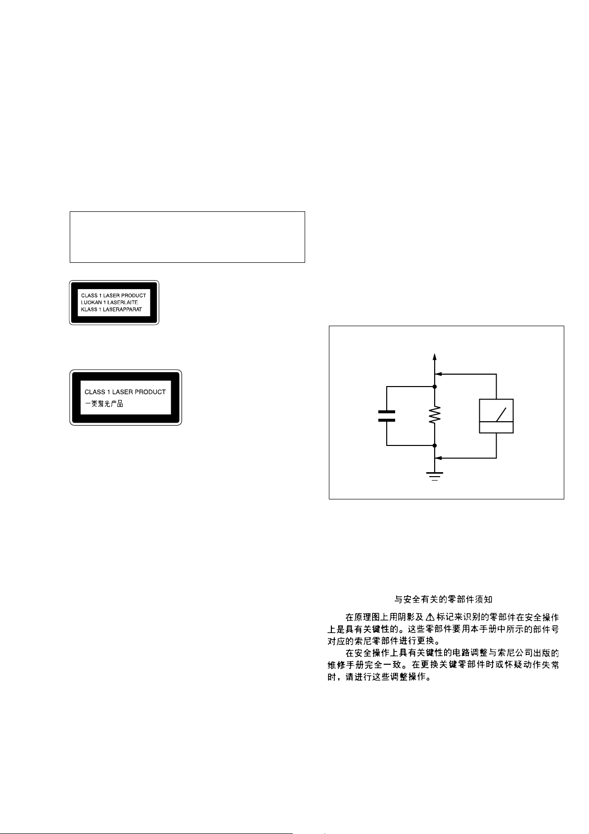
3. Measuring the voltage drop across a resistor by means of a V OM
or battery-operated A C voltmeter . The “limit” indication is 0.75
V, so analog meters must have an accurate low-voltage scale.
The Simpson 250 and Sanwa SH-63Trd are examples of a passive VOM that is suitable. Nearly all battery operated digital
multimeters that have a 2 V A C range are suitable. (See Fig. A)
SAFETY-RELATED COMPONENT WARNING!!
COMPONENTS IDENTIFIED BY MARK 0 OR DOTTED
LINE WITH MARK 0 ON THE SCHEMATIC DIAGRAMS
AND IN THE PARTS LIST ARE CRITICAL TO SAFE
OPERATION. REPLACE THESE COMPONENTS WITH
SONY PARTS WHOSE PART NUMBERS APPEAR AS
SHOWN IN THIS MANUAL OR IN SUPPLEMENTS PUBLISHED BY SONY.
Fig. A. Using an AC voltmeter to check AC leakage.
ATTENTION AU COMPOSANT AYANT RAPPORT
À LA SÉCURITÉ!
LES COMPOSANTS IDENTIFIÉS P AR UNE MARQUE 0
SUR LES DIAGRAMMES SCHÉMATIQUES ET LA LISTE
DES PIÈCES SONT CRITIQUES POUR LA SÉCURITÉ
DE FONCTIONNEMENT. NE REMPLACER CES COMPOSANTS QUE PAR DES PIÈCES SONY DONT LES
NUMÉROS SONT DONNÉS DANS CE MANUEL OU
DANS LES SUPPLÉMENTS PUBLIÉS PAR SONY.
3

HCD-S550/S880
Ver 1.4
TABLE OF CONTENTS
SELF DIAGNOSIS FUNCTION.................................... 2
1. SERVICING NOTES ............................................... 5
2. GENERAL
Location of Controls ...................................................... 6
3. DISASSEMBLY
3-1. Disassembly Flow .......................................................... 9
3-2. Front Panel Section, Side Panel (L)/(R) ........................ 10
3-3. I/O Board......................................................................... 10
3-4. SEL Board ....................................................................... 11
3-5. DVD Board...................................................................... 11
3-6. Mechanism Deck Section (CDM72B-DVBU12).......... 12
3-7. POWER SW Board, DDCON Board............................. 12
3-8. Power Board ................................................................... 13
3-9. AMP Board .................................................................... 13
3-10. Optical Pick-up (DVBU12) ........................................... 14
3-11. RELAY Board ................................................................ 14
3-12. Holder (AT) Assy, Retainer (Chassis) Block................. 15
3-13. Belt (L2) ......................................................................... 15
3-14. Pulley (RTR) Assy ......................................................... 16
3-15. Belt (CK) ........................................................................ 16
3-16. Pulley (SPT) Assy .......................................................... 17
3-17. Belt (CK), Motor (CK) Assy (M751) ............................ 17
4. ASSEMBLY
4-1. How to Install Pulley (SPT) Assy .................................. 18
4-2. How to Install Pulley (RTR) Assy ................................. 18
4-3. How to Install Rotary Encoder (Mode) (S741)............. 19
5. TEST MODE............................................................. 20
6. ELECTRICAL ADJUSTMENT........................... 27
7. DIAGRAMS
7-1. Block Diagram – RF SERVO Section – ....................... 28
7-2. Block Diagram – AUDIO (DSP) Section – .................. 29
7-3. Block Diagram – AUDIO OUT, PANEL Section – ..... 30
7-4. Block Diagram – VIDEO Section – ............................. 31
7-5. Block Diagram – MECHANISM DECK,
POWER SUPPLY Section – .......................................... 32
7-6. Note for Printed Wiring Boards and
Schematic Diagrams ...................................................... 33
7-7. Printed Wiring Boards – RF Section – ......................... 34
7-8. Schematic Diagram – RF Section –.............................. 35
7-9. Printed Wiring Boards
– MECHANISM DECK Section – ................................ 36
7-10. Schematic Diagram
– MECHANISM DECK Section – ................................ 37
7-11. Printed Wiring Board
– DVD Board (Component Side) – ............................... 38
7-12. Printed Wiring Board
– DVD Board (Conductor Side) – ................................. 39
7-13. Schematic Diagram – DVD Board (1/10) – ................. 40
7-14. Schematic Diagram – DVD Board (2/10) – ................. 41
7-15. Schematic Diagram – DVD Board (3/10) – ................. 42
7-16. Schematic Diagram – DVD Board (4/10) – ................. 43
7-17. Schematic Diagram – DVD Board (5/10) – ................. 44
7-18. Schematic Diagram – DVD Board (6/10) – ................. 45
7-19. Schematic Diagram – DVD Board (7/10) – ................. 46
7-20. Schematic Diagram – DVD Board (8/10) – ................. 47
7-21. Schematic Diagram – DVD Board (9/10) – ................. 48
7-22. Schematic Diagram – DVD Board (10/10) – ............... 49
7-23. Printed Wiring Board – AMP Section (1/2) – .............. 50
7-24. Printed Wiring Boards – AMP Section (2/2) –............. 51
7-25. Schematic Diagram – AMP Section (1/2) – ................. 52
7-26. Schematic Diagram – AMP Section (2/2) – ................. 53
7-27. Printed Wiring Board – I/O Section (1/2) – .................. 54
7-28. Printed Wiring Boards – I/O Section (2/2) – ................ 55
7-29. Schematic Diagram – I/O Section (1/2) – .................... 56
7-30. Schematic Diagram – I/O Section (2/2) – .................... 57
7-31. Printed Wiring Boards
– DC-DC CONVERTER Section – ............................... 58
7-32. Schematic Diagram
– DC-DC CONVERTER Section – ............................... 59
7-33. Printed Wiring Boards – CONTROL Section – ........... 60
7-34. Schematic Diagram – CONTROL Section –................ 61
7-35. Printed Wiring Board – FL Board – ............................. 62
7-36. Schematic Diagram – FL Board – ................................ 63
7-37. Printed Wiring Board – POWER Section (1/2) –......... 64
7-38. Printed Wiring Boards – POWER Section (2/2) – ....... 65
7-39. Schematic Diagram – POWER Section – .................... 66
7-40. IC Pin Function Description .......................................... 84
8. EXPLODED VIEWS
8-1. General Section ............................................................. 102
8-2. Front Panel Section-1.................................................... 103
8-3. Front Panel Section-2.................................................... 104
8-4. Chassis Section-1 .......................................................... 105
8-5. Chassis Section-2 .......................................................... 106
8-6. Chassis Section-3 .......................................................... 107
8-7. Chassis Section-4 .......................................................... 108
8-8. Mechanism Deck Section-1 (CDM72B-DVBU12)...... 109
8-9. Mechanism Deck Section-2 (CDM72A-DVBU12) ..... 110
8-10. Mechanism Deck Section-3 (CDM72A-DVBU12) ..... 111
8-11. Mechanism Deck Section-4 (CDM72A-DVBU12) ..... 112
8-12. Mechanism Deck Section-5 (CDM72A-DVBU12) ..... 113
8-13. Mechanism Deck Section-6 (CDM72A-DVBU12) ..... 114
8-14. Mechanism Deck Section-7 (CDM72A-DVBU12) ..... 115
8-15. Optical Pick-up Section (DVBU12) ............................. 116
9. ELECTRICAL PARTS LIST ............................. 117
4
SECTION 1
)
SER VICING NOTES
HCD-S550/S880
Ver 1.6
NOTES ON HANDLING THE OPTICAL PICK-UP
BLOCK OR BASE UNIT
The laser diode in the optical pick-up block may suffer electrostatic break-down because of the potential difference generated
by the charged electrostatic load, etc. on clothing and the human
body.
During repair, pay attention to electrostatic break-down and also
use the procedure in the printed matter which is included in the
repair parts.
The flexible board is easily damaged and should be handled with
care.
NOTES ON LASER DIODE EMISSION CHECK
The laser beam on this model is concentrated so as to be focused
on the disc reflective surface by the objective lens in the optical
pick-up block. Therefore, when checking the laser diode emission, observe from more than 30 cm away from the objective lens.
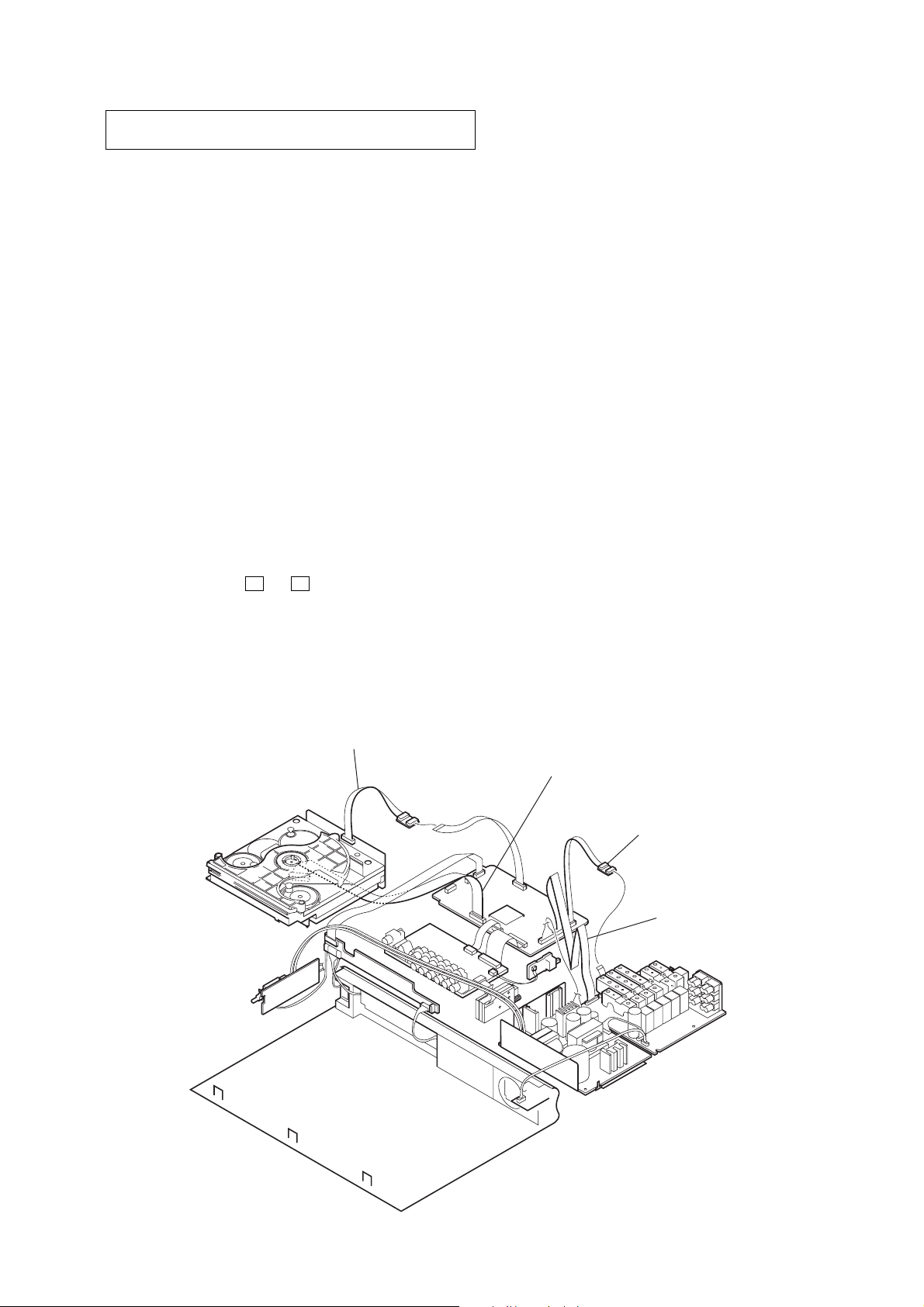
JIG ON REPAIRING
When repairing this set, etc., connect the extension cable as the
figure shown below.
RELEASING THE DISC SLOT LOCK
The disc slot lock function for the antitheft of an demonstration
disc in the store is equipped.
CHECKING OF OPERATIONS WITH REMOTE COMMANDERS OF DIFFERENT MODELS
Some of the signal of remote commander vary between generation of player.
Between DAV-S400/S500/S800/C450/C700/C900 and DAV-S550/
S880/C770/C900, remote commander signal codes of “FUNCTION”, “BAND”, “ST/MONO” and “MEMORY” are different.
Take notice of the above when you check the operation with remote commanders of different models.
NOTE OF REPLACING THE DVD BOARD
When replacing the DVD board, since the adjustment value is not
set up correctly, “Drive Auto Adjustment” can’t be performed.
In this case, initialize Memory in the following procedures.
Procedure:
1. Set the test mode. (See page 20)
2. Press the [2] key of the remote commander , and set the “DRIVE
MANUAL OPERATION”. (See page 22)
3. Press the [6] key of the remote commander, and set the “2-6,
Memory Check”. (See page 24)
4. Press the [CLEAR] key of the remote commander, and initialize Memory.
Releasing Procedure:
1. Press two buttons of A and x simultaneously for three seconds.
2. The message “UNLOCKED” is displayed and the slot is unlocked.
Note: When “LOCKED” is displayed, the slot lock is not released by
turning power on/off with the [POWER] button.
extension cable (with relay board)
(RELAY board-DVD board)
(Part No. J-2501-091-A)
extension cable
(RF board-DVD board)
(Part No. J-2501-217-A)
extension cable
(DVD board-AMP board)
(Part No. J-8000-024-A)
extension cable
(DVD board-AMP board
(Part No. J-2501-198-A)
5
HCD-S550/S880
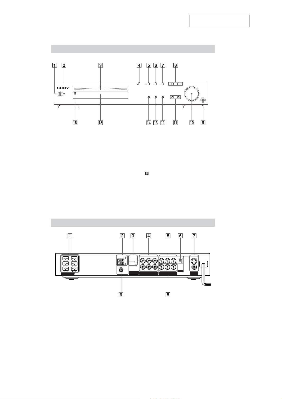
LOCATION OF CONTROLS
Front Panel
SECTION 2
GENERAL
This section is extracted from
instruction manual.
STANDBY
1 POWER switc
2 STANDBY indicator
3 Disc slot
4 A (Eject)
5 H (play)
6 X (pause)
7 x (stop)
8 ./> PREV/NEXT, PRESET –/+
Rear Panel
FUNCTION BAND DISPLAY SOUND FIELD
9 PHONES jack
q; VOLUME control
qa SOUND FIELD –/+
qs DISPLAY
qd BAND
qf FUNCTION
qg Front panel display
(remote sensor)
qh
PHONES
R
OPTICAL
DIGITAL
IN
VIDEO 2
S VIDEO (DVD ONLY)
VIDEO
MONITOR
OUT
FRONT
REAR
L
L
IMPEDANCE
USE
WOOFER 3Ω
EXCEPT
WOOFER 3Ω
FRONT
R
CENTER WOOFER
REAR
R
SPEAKER
1 SPEAKER jacks
2 AM antenna
3 COMPONENT VIDEO OUT/SCAN
SELECT switch
4 VIDEO 1 jacks
AM
COAXIAL
FM
75Ω
AUDIO OUT
VIDEO OUT VIDEO IN
SCAN SELECT
SELECTABLE
INTERLACE
COMPONENT
VIDEO OUT
LR LR
LR
AUDIO IN VIDEO IN
VIDEO 1
AUDIO IN
YPB/CBPR/C
COMPONENT VIDEO OUT
6 DIGITAL IN (OPTICAL) jack
7 MONITOR OUT (VIDEO/S VIDEO)
jacks
8 COMPONENT VIDEO OUT jacks
9 FM 75Ω COAXIAL antenna jack
5 VIDEO 2 jacks
6
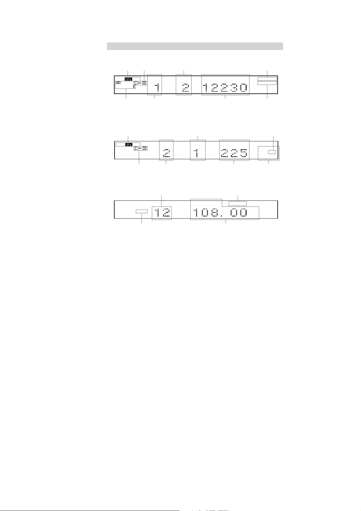
Front Panel Display
When playing back a DVD
Current sound
Playing status
Current chapter number
Lights up when you can
change the angle
HCD-S550/S880
TITLE CHAPTER H M S
PCM
DIGITAL
PRO LOGIC
Current surround
format
Current title
number
Playing time Current repeat mode
When playing back a Super Audio CD, CD, VIDEO CD, or MP3
Current index number
(The index indicator does not appear
Current sound
SACD
Playing status
PCM
Current track number Current play mode
during Super Audio CD or MP3
playback.)
TRACK INDEX M S
Playing time
When listening to the radio
Preset number Monaural/Stereo effect
TUNED MONO ST
FM AM
Current band
Current station
ANGLE
REPEAT 1
Lights up during
PBC playback
(VIDEO CD only)
REPEAT 1
PROG PBC
SHUFFLE
MHz
7
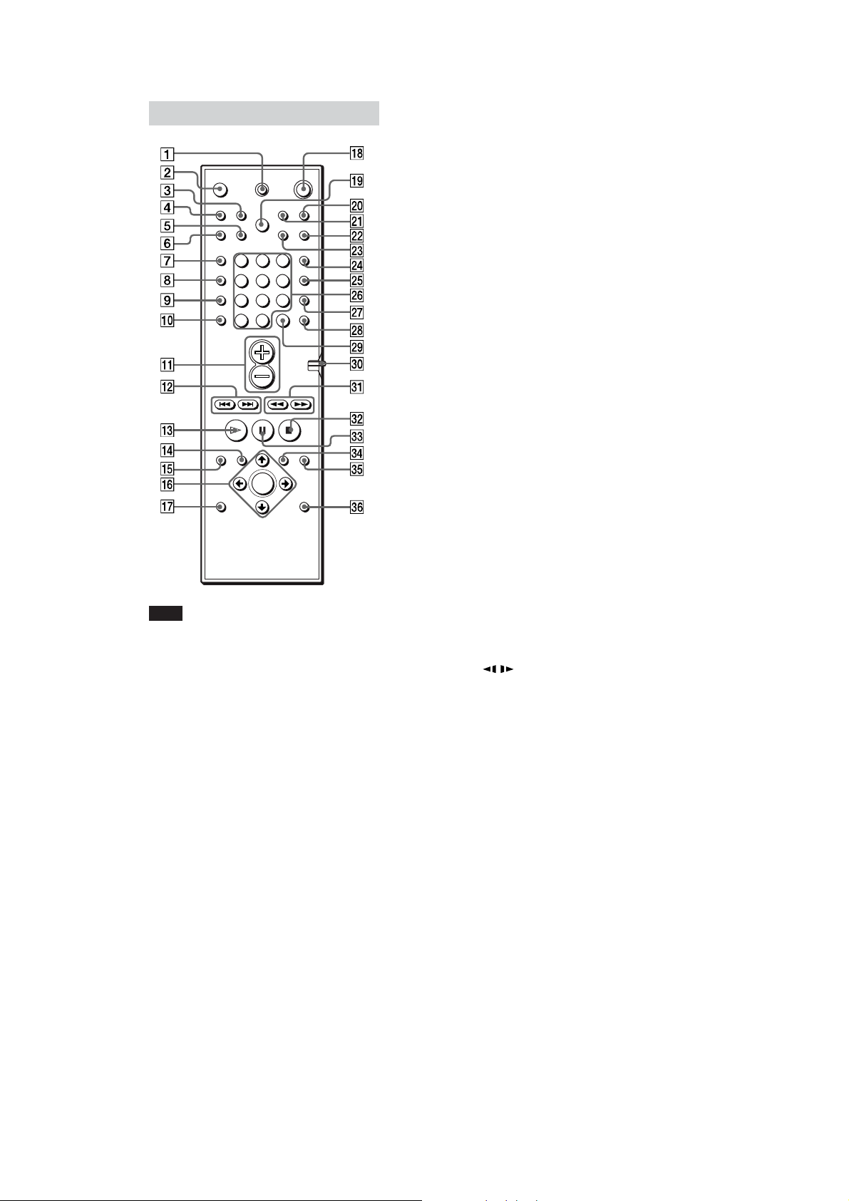
HCD-S550/S880
Remote
123
456
7
89
>
10
10/0
1 TV [/1 (on/standby)
2 Z (EJECT)
3 NAME
4 STEREO/MONO
5 MEMORY
6 CLEAR
7 PLAY MODE
8 AUDIO
9 ANGLE
q; SUBTITLE
qa VOL +/–
qs ./> PREV/NEXT, TV CH –/+,
PRESET –/+
qd H PLAY/SELECT
qf DVD TOP MENU
qg DVD DISPLAY
qh C/X/x/c/ENTER
qj DVD SETUP
qk 1 (standby)
ql DIMMER
w; TV/VIDEO
wa REPEAT
ws MUTING
wd TIME
wf FUNCTION
Note
This remote control glows in the dark. However,
before glowing, the remote must be exposed to light
for awhile.
wg BAND
wh Number buttons
wj SOUND FIELD
wk DISPLAY
wl ENTER
e; COMMAND MODE DVD TV switch
ea m/M/
/ SLOW, TUNING –/+
es x STOP
ed X PAUSE
ef DVD MENU
eg O RETURN
eh AMP MENU
8
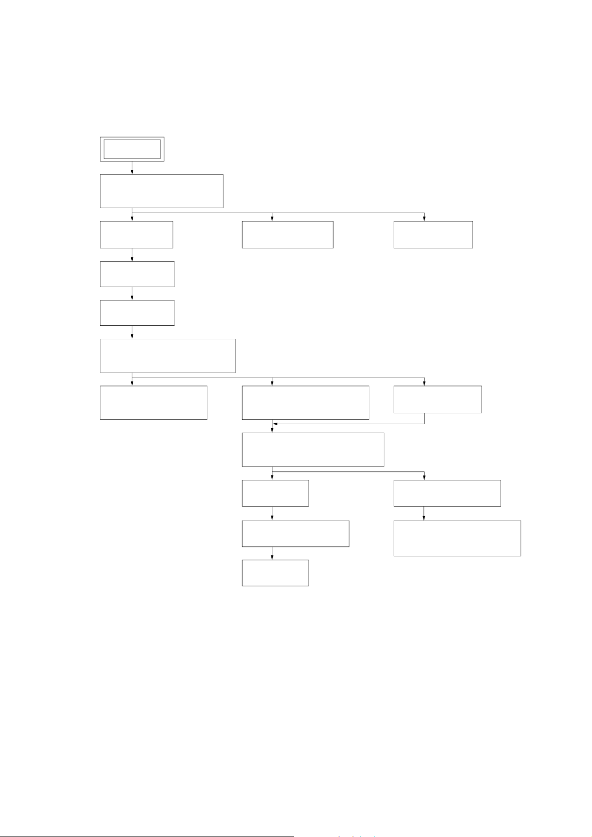
• This set can be disassembled in the order shown below.
3-1. DISASSEMBLY FLOW
SET
3-2. FRONT PANELSECTION,
SIDE PANEL (L)/(R)
(Page 10)
HCD-S550/S880
SECTION 3
DISASSEMBLY
3-3. I/O BOARD
(Page 10)
3-4. SEL BOARD
(Page 11)
3-5. DVD BOARD
(Page 11)
3-6. MECHANISM DECK
SECTION (CDM72B-DVBU12)
(Page 12)
3-7. POWER SW BOARD,
DDCON BOARD
(Page 12)
3-8. POWER BOARD
(Page 13)
3-10. OPTICAL PICK-UP BLOCK
(DVBU12)
(Page 14)
3-12. HOLDER (AT) ASSY.
RETAINER (CHASSIS) BLOCK
(Page 15)
3-13. BELT (L2)
(Page 15)
3-9. AMP BOARD
(Page 13)
3-11. RELAY BOARD
(Page 14)
3-16. PULLEY (SPT) ASSY
(Page 17)
3-14. PULLEY (RTR) ASSY
(Page 16)
3-15. BELT (CK)
(Page 16)
3-17. BELT (CK),
MOTOR (CK) ASSY (M751)
(Page 17)
9
HCD-S550/S880
)
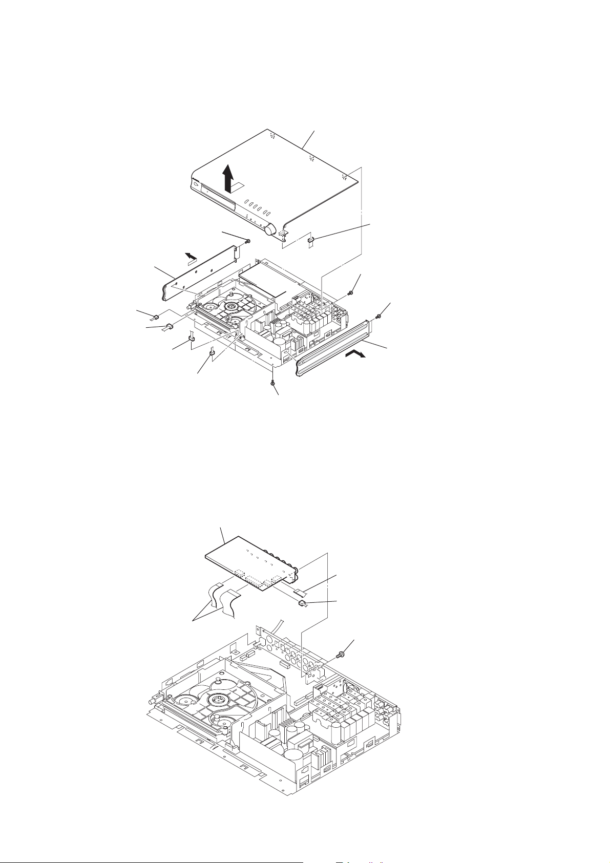
Note: Follow the disassembly procedure in the numerical order given.
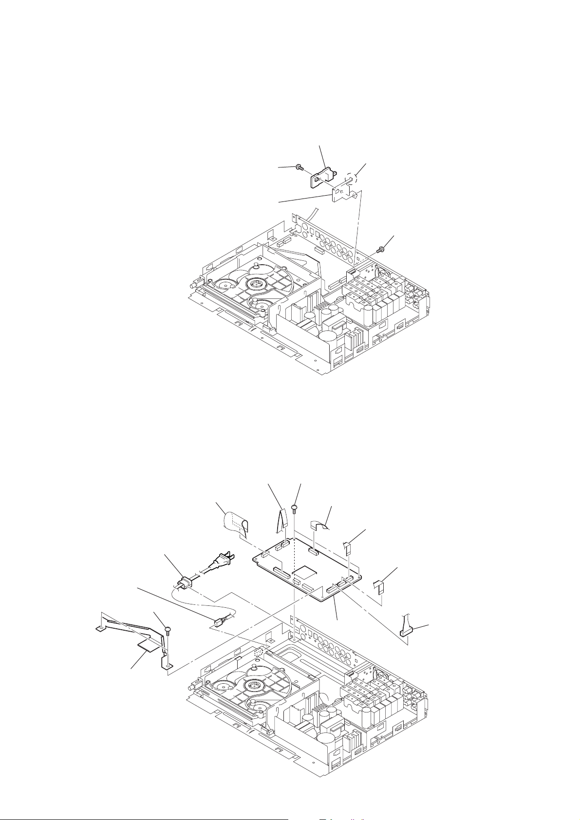
3-2. FRONT PANEL SECTION, SIDE PANEL (L)/(R)
3
0
two screws
0
two screws
×
8)
×
8)
qa
side panel (L)
8
connector
(CN803)
(BVTP3
(BVTP3
9
front panel section
1
4
connector (CN900)
three screws
×
(BVTP3
8)
qs
two screws
(BVTP3
×
8)
7
3-3. I/O BOARD
2
connector
(CN802)
6
connector
(CN804)
5
connector
(CN805)
two flexible flat cables
(CN202, 203)
5
I/O board
2
three screws
(BVTP3
×
8)
1
flexible flat cable
(CN201)
2
connector (CN205
4
qd
side panel (R)
seven screws
(BVTP3
×
8)
10
3-4. SEL BOARD
r
3
screw
(DIA. 2.6
4
retainer
×
5
8)
SEL board
2
claw
1
screw
(DIA. 2.6
HCD-S550/S880
×
8)
3-5. DVD BOARD
8
power cord block
9
connector
(CN900)
9
two screws
(BVTP3
×
8)
0
retainer
5
flexible board
(CN401)
1
flexible flat cable
(CN005)
qa
two screws (BVTP3
2
flexible flat cable
(CN006)
qs
DVD board
×
8)
3
flexible flat cable
(CN001)
4
flexible flat cable
(CN004)
6
connecto
(CN008)
11

HCD-S550/S880
)
3-6. MECHANISM DECK SECTION (CDM72B-DVBU12)
1
flexible flat cable
(CN701)
3
mechanism deck
(CDM72B-DVBU12)
2
four screws
×
(BVTP3
8)
3-7. POWER SW BOARD, DDCON BOARD
6
four screws
(P2
×
5
power button section
8
flexible flat cable
(CN814)
9
connector
(CN807)
4
connector
(CN901)
0
two screws
(BVTP3
6)
×
7
power SW board
8)
2
four screws
(BVTP3
3
×
8)
1
connector (CN902
12
qa
DDCON board
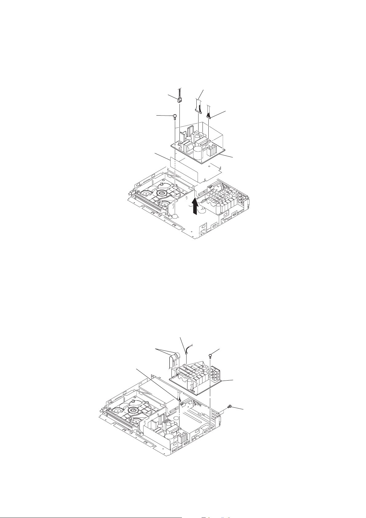
3-8. POWER BOARD
d
4
four screws
(BVTP3
6
power sheet
3
connector
(CN902)
×
8)
2
connector
(CN903)
1
connector
(CN904)
7
HCD-S550/S880
power boar
3-9. AMP BOARD
1
two wires (flat type)
(CN301, 305)
3
connector
(CN904)
2
connector
(CN302)
5
4
four screws
(BVTP3
6
×
8)
AMP board
5
two screws
×
(BVTP3
8)
13
HCD-S550/S880
k
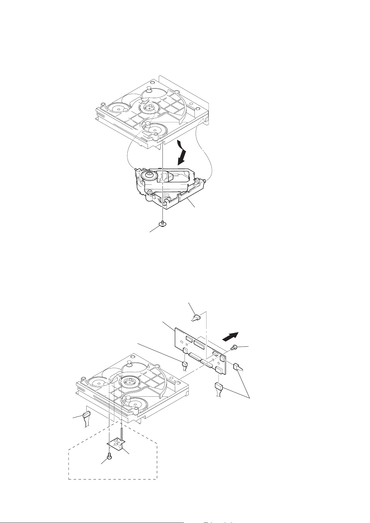
3-10. OPTICAL PICK-UP BLOCK (DVBU12)
3-11. RELAY BOARD
1
screw
(PTPWHM2.6)
9
8
connecter
(CN706)
relay board
7
connector
(CN702)
2
optical pick-up bloc
(DVBU12)
5
4
two screws
(BTP2.6
×
6)
14
3
connector
(CN741)
S880
1
three screws
(BTP2.6
× 6
6
two connector
(CN703, 707)
2
retainer
)
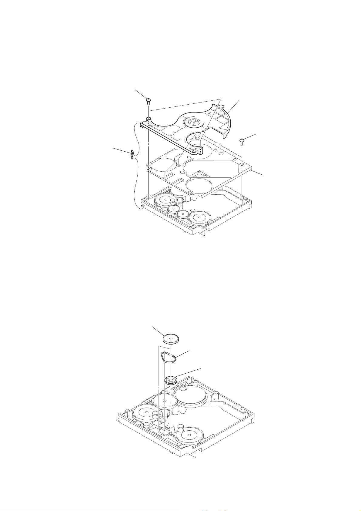
3-12. HOLDER (AT) ASSY, RETAINER (CHASSIS) BLOCK
k
2
three screws
(BTP2.6
×
8)
1
tension spring
(S5)
3
holder (AT) assy
4
HCD-S550/S880
four screws
(BTP2.6
×
6)
5
retainer (chassis) bloc
3-13. BELT (L2)
1
two gears
(S1)
2
belt (L2)
3
pulley (LDG)
15
HCD-S550/S880
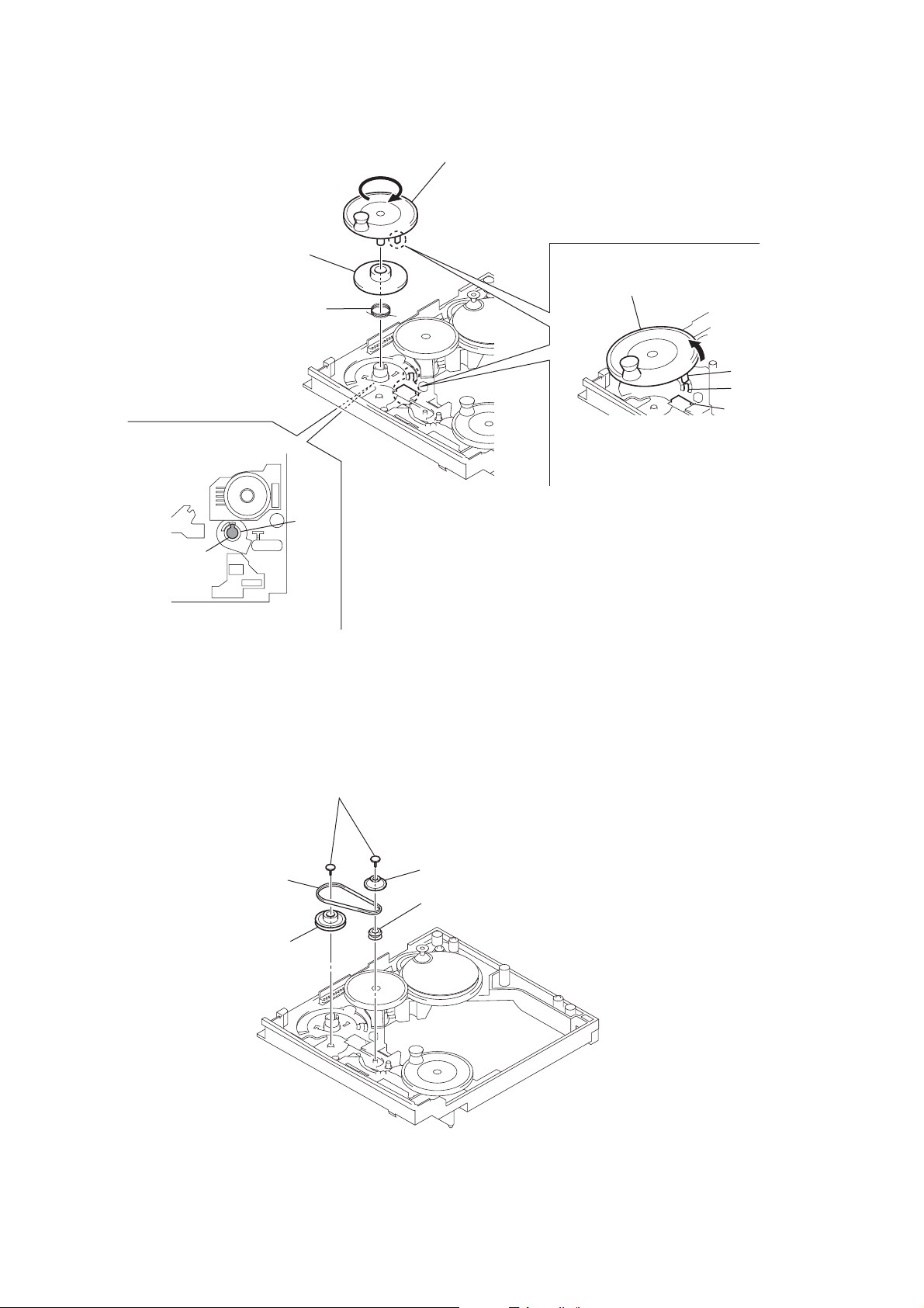
3-14. PULLEY (RTR) ASSY
2
3
gear (L4)
torsion spring
(L)
A
1
Rotate the pulley (RTR) assy in the direction of arrow
to disengage the shaft of the pulley (RTR) assy from
the hole of the chassis (refer to fig. 1), and remove it.
pulley (RTR) assy
B
Tilting the pulley (RTR) assy in the direction
of arrow B, move it over the claw and
the connector of the chassis.
A
boss
claw
connector
shaft
(pulley (RTR) assy)
3-15. BELT (CK)
front
– bottom view –
fig. 1
3
belt (CK)
5
pulley (LCG)
hole
1
two bushings
(CDM72)
2
gear (L5)
4
pulley (L5)
16
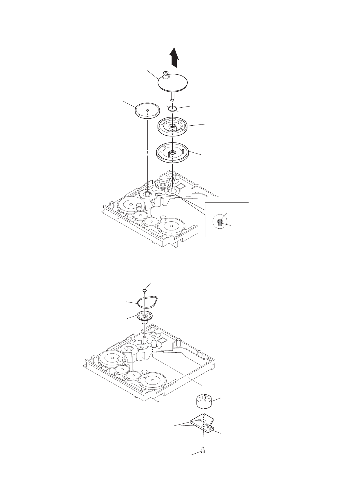
3-16. PULLEY (SPT) ASSY
y
2
pulley (SPT) assy
3
gear (S2)
4
torsion spring (S)
5
gear (SPT)
6
gear (KT)
HCD-S550/S880
3-17. BELT (CK), MOTOR (CK) ASSY (M751)
1
busing (CDM72)
2
belt (CK)
3
pulley (CKG)
hole
shaft
(pulley (SPT) assy
1
Rotate the pulley (SPT) assy to fit position
of the shaft to the hole of the chassis.
4
two solders
5
two screws
(BTP2.6
7
motor (CK) ass
(M751)
6
CK motor board
×
6)
17
HCD-S550/C880
SECTION 4
ASSEMBLY
• This set can be assembled in the order shown below.
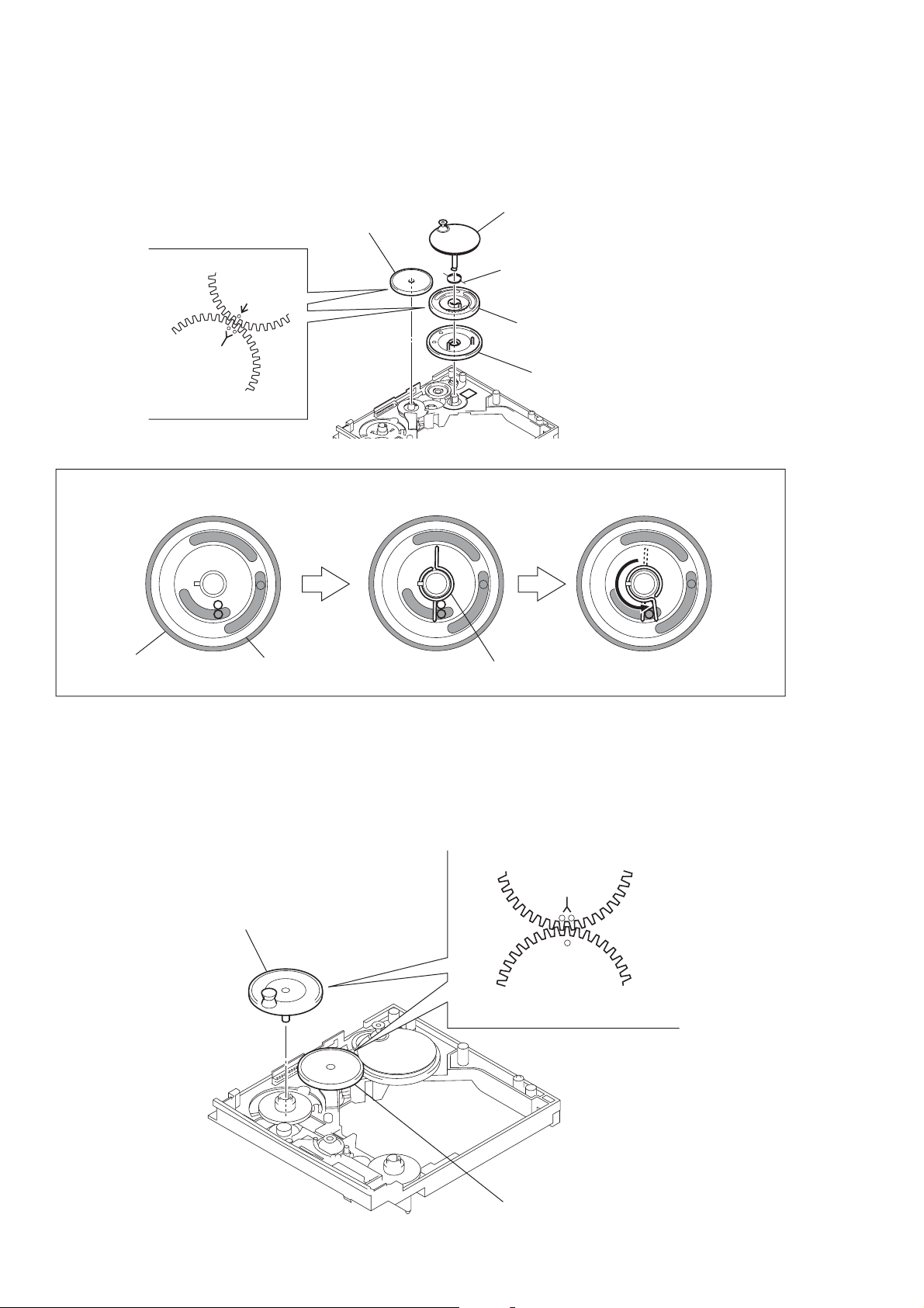
4-1. HOW TO INSTALL PULLEY (SPT) ASSY
4
gear (S2)
gear (S2)
5
pulley (SPT) assy
3
torsion spring (S) (Note)
2
gear (SPT)
gear (SPT)
Note: installation of torsion spring (S)
gear (KT)
gear (SPT)
4-2. HOW TO INSTALL PULLEY (RTR) ASSY
torsion spring (S)
1
gear (KT)
18
gear (S2)
pulley (RTR) assy
pulley
(RTR) assy
gear (S2)
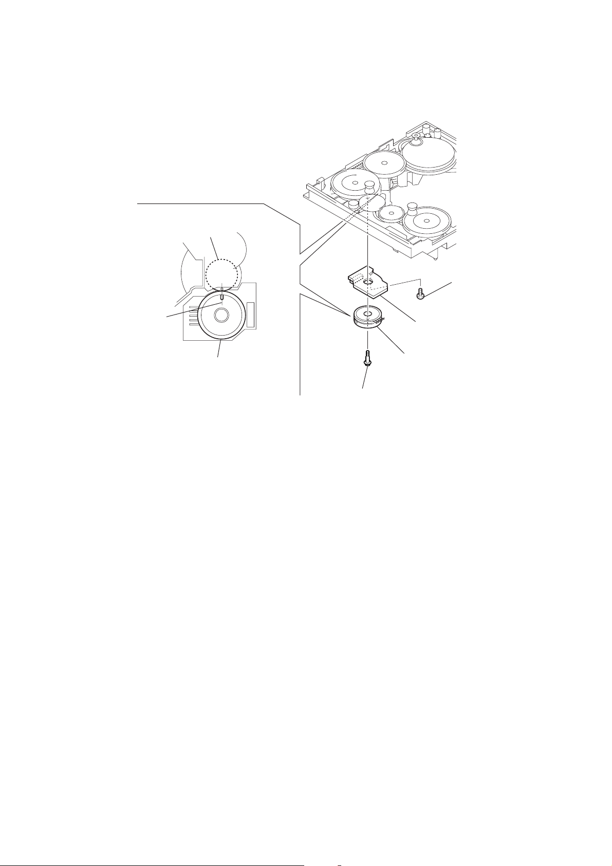
4-3. HOW TO INSTALL ROTARY ENCODER (MODE) (S741)
cam (CDM72)
2
screw
(BTP2.6 × 6)
HCD-S550/S880
linearly
rotary encoder (mode)
(S741)
-bottom view-
4
screw
(PWH,2 × 6)
1
encoder board
3
rotary encoder (mode)
(S741)
19

HCD-S550/S880
Ver 1.4
SECTION 5
TEST MODE
[GENERAL DESCRIPTION]
The T est Mode allows you to make dia gnosis and adjustment easily
using the remote commander and monitor TV. The instructions,
diagnostic results, etc. are given on the on-screen display (OSD).
[TEST DISC LIST]
Use the following test disc on test mode.
TDV-520CSO (DVD-SL): PART No. J-2501-236-A
LIV-P01 (CD): PART No. 4-999-032-01
TDV-540C (DVD-DL): PART No. J-2501-235-A
Note: Do not use exiting test disc for DVD.
[STARTING TEST MODE]
1. Press the [POWER] button to turn the power on, and set the
function to DVD.
2. While pressing the x and [DISPLAY] button, turn the
[VOLUME] knob clockwise to enter the test mode.
3. It displays “TEST MODE” on the fluorescent indicator tube,
and displays the Test Mode Menu on the monitor screen as
follows. (At the bottom of the menu screen, the model name
and revision number are displayed)
Test Mode Menu
0. Syscon Diagnosis
1. Drive Auto Adjustment
2. Drive Manual Operation
3. Mecha Aging
4. Emergency History
5. Mecha Error History
6. Version Information
7. Video Level Adjustment
Exit: POWER Key
Model :DAV-Sxxx
Revision :x.xx
4. To execute each function, select the desired menu and press its
number on the remote commander (RM-SS880J).
5. To release from test mode, press the
the power off.
[POWER] button and tur n
[OPERATING TEST MODE]
0. SYSCON DIAGNOSIS
The same contents as board detail check by serial interface can be
checked from the remote commander operation.
On the Test Mode Menu screen, press [10/0] key on the remote
commander, and the following Check Menu will be displayed.
### Syscon Diagnosis ###
Check Menu
0. Quit
1. All
2. Version
3. EEPROM
4. SPIO
5. SD Bus
6. Video
7. Audio
0-1. All (All items continuous check)
This menu checks all diagnostic items continuously. Normally, all
items are checked successively one after another automatically
unless an error is found, but at a certain item that requires judgment
through a visual check to the result, the following screen is displayed
for the key entry.
• Example display
### Syscon Diagnosis ###
Diag All Check
No.2 Version
2-3. ROM Check Sum
Check Sum = 2320
Press NEXT Key to Continue
Press PREV Key to Repeat
For the ROM Check, the check sum calculated by the Syscon is
output, and therefore you must compare it with the specified value
for confirmation.
Following the message, press the [NEXT ] button to go to the
next item, or press the [ PREV] button to repeat the same
operation again.
To quit the diagnosis and return to Check Menu screen, press the
.
>
[RETURN] key on the remote commander to display Check Menu.
• Error occurred
If an error occurred, the diagnosis is suspended and error is displayed.
Press the
diagnosis, or press the [ PREV] button to repeat the same check
where an error occurred, or press the [NEXT ] button to continue
the check from the item next to faulty item.
General Description of Checking Method
Selecting 2 and subsequent items calls the submenu screen of each
item. And selecting 2 and subsequent items executes respective
menus and outputs the results.
For the contents of each submenu, see “Check Items List” as below .
Check Items List:
[RETURN] key on the remote commander to quit the
.
>
0-2. Version
0-2-1. All
0-2-2. Revision
0-2-3. ROM Check Sum
0-2-4. Model Type
0-2-5. Region
0-3. EEPROM Check
0-3-1. Sampling Check
0-3-2. Detail Check
0-4. GP I/O Check
0-5. SD Bus Check
0-6. Video Check
0-7. Audio Check
0-0. Quit
Quit the Syscon Diagnosis and return to the Test Mode Menu.
20
0-2. Version
0-2-2. Revision
The revision number of ROM (IC204) that the program for
the DVD system processor (IC206) is stored.
(4 digits hexadecimal number)

HCD-S550/S880
0-2-3. ROM Check Sum
The revision number of ROM (IC204) that the program for
the DVD system processor (IC206) is stored.
0-2-4. Model Type
Model name is displayed. (DAV-S550 or DAV-S880)
0-2-5. Region
Model destination code is displayed. (2 digits number)
0-3. EEPROM Check
0-3-1. Sampling Check
EEPROM check at every 64 words.
It compares read data with write data of each address. When
there are discrepancies between two data, it displays error.
0-3-2. Detail Check
EEPROM check at every 1 word.
It compares read data with write data of each address. When
there are discrepancies between two data, it displays error.
0-4. GP I/O Check
Pull up/down setting check of the DVD system processor (IC206)
pin 150, 151 and 154 (for clock setting port).
0-5. SD Bus Check
SD bus data check between DVD decoder (IC701) and D-RAM
(IC706).
0-6. Video Check
Output the color bars for video level adjustment.
0-7. Audio Check
Output the test signal (1kHz sine wave) for 5.1 CH test.
1. DRIVE AUTO ADJUSTMENT
On the Test Mode Men u screen, press the [1] key on the remote
commander, and the Adjustment Menu will be displayed.
## Drive Auto Adjustment ##
Adjustment Menu
0. ALL
1. DVD-SL
2. CD
3. DVD-DL
by pressing the [RETURN] button on the remote commander.
Note: During adjustment of each disc, the measurement for disc type judg-
ment is made. As automatic adjustment does not judge the disc
type unlike conventional models, take care not to insert wrong type
discs. Also, do not give a shock during adjustment.
1-1. DVD-SL (single layer)
Press the [1] key on the remote commander and insert a DVD single
layer disc following the message. Then the adjustment will be made
through the steps below, then adjusted values will be written to the
EEPROM.
DVD Single Layer Disc Adjustment Steps:
1. Sled tilt reset
2. Disc check memory SL
3. Wait 300 msec
4. Set disc type SL
5. LD on
6. Spindle start
7. Wait 1 sec
8. Focus servo on 0
9. Auto track offset adjust
10. CLVA on
11. Wait 500 msec
12. Tracking on
13. Wait 1 sec
14. Sled on
15. Check CLV on
16. Auto LFO adjust
17. Auto focus offset adjust
18. Auto tilt position adjust
19. Auto focus gain adjust
20. Auto focus offset adjust
21. EQ boost adjust
22. Auto loop filter offset adjust
23. Auto track gain adjust
Search Check
24. 32 track jump forward
25. 32 track jump reverse
26. 500 track jump forward
27. 500 track jump reverse
28. All servo stop
29. EEP copy loop filter offset
1-2. CD
Press the
following the message. Then the adjustment will be made through
the steps below , then adjusted values will be written to the EEPR OM.
[2] key on the remote commander and insert a CD disc
Exit: RETURN
Normally, [10/0] is selected to adjust DVD (single layer), CD and
DVD (dual layer) in this order . But, individual items can be adjusted
for the case where adjustment is suspended due to an error. In this
mode, the adjustment can be made easily through the operation
following the message displayed on the screen.
The disc used for adjustment must be the one specified for
adjustment.
1-0. ALL
Press the [10/0] key on the remote commander, and the servo set
data in EEPROM will be initialized. Then, 1. DVD-SL disc, 2. CD
disc and 3. DVD-DL disc are adjusted in this order.
Each time one disc was adjusted, it is ejected. Replace it with the
specified disc following the message. Y ou can finish the adjustment
CD Adjustment Steps
1. Sled tilt rest
2. Disc check memory CD
3. Wait 500 msec
4. Set disc type CD
5. LD on
6. Spindle start
7. Wait 500 msec
8. Focus servo on 0
9. Auto track offset adjust
10. CLVA on
11. Wait 500 msec
12. Tracking on
13. (TC display start)
14. Wait 1 sec
15. Jitter display start
16. Sled ON
17. Check CLV on
21
HCD-S550/S880
18. Auto loop filter offset adjust
19. Auto focus offset adjust
20. Auto focus gain adjust
21. Auto focus offset adjust
22. EQ boost adjust
23. Auto LFO Adjust
24. Auto track gain adjust
Search Check
25. 32Tj forward
26. 32Tj reverse
27. 500Tj forward
28. 500Tj reverse
29. All servo stop
1-3. DVD-DL (dual layer)
Press the [3] key on the remote commander and insert a DVD dual
layer disc following the message. Then the adjustment will be made
through the steps below, then adjusted values will be written to the
EEPROM.
DVD Dual Layer Disc Adjustment Steps:
1. Sled tilt reset
2. Disc check memory DL
3. Wait 500 msec
4. Set disc type DL
5. LD on
6. Spindle start
7. Wait 1 sec
Layer 1 Adjust
8. Focus servo on 0
9. Auto track offset adjust
10. CLVA on
11. Wait 500 msec
12. Tracking on
13. Wait 500 msec
14. Sled on
15. Check CLV lock
16. Auto loop filter offset adjust, Auto focus adjust
17. Auto focus gain adjust
18. Auto focus offset adjust
19. EQ boost adjust
20. Auto loop filter offset adjust
21. Auto Track Gain Adjust
Search Check
22. 32 track jump forward
23. 32 track jump reverse
24. 500 track jump forward
25. 500 track jump reverse
Layer 0 Adjust
26. Focus jump (L1 t L0)
27. Auto track offset adjust L0
28. CLVA on
29. Wait 500 msec
30. Tracking on
31. Wait 500 msec
32. Sled on
33. Check CLV lock
34. Auto focus filter offset adjust
35. Auto Focus Adjust
36. Auto focus gain adjust
37. Auto focus offset adjust
38. EQ boost adjust
39. Auto Loop Filter Offset
40. Auto track gain adjust
Search Check
41. 32 track jump forward
42. 32 track jump reverse
43. 500 track jump forward
44. 500 track jump reverse
Layer Jump Check
45. Layer jump (L0 ? L1)
46. Layer jump (L1 ? L0)
47. All servo stop
2. DRIVE MANUAL OPERATION
Note: This mode is used for design, and not used in service fundamen-
tally.
On the Test Mode Menu screen, press the [2] key on the remote
commander, and the Operation Menu will be displayed. For the
manual operation, each servo on/off control and adjustment can be
executed manually.
## Drive Manual Operation ##
Operation Menu
1. Disc Type
2. Servo Control
3. Track/Layer Jump
4. Non EEPROM Write Adjust
5. EEPROM Write Adjust
6. Memory Check
7. Disc Check Memory
8. Error Rate Display
9. SACD Water Mark
Exit: RETURN
In using the manual operation menu, take care of the following
points. These commands do not provide protection, thus requiring
correct operation. The sector address or time code field is displayed
when a disc is loaded.
Note:
1. Set correctly the disc type to be used on the Disc Type screen.
2. In case of an alarm, immediately press the x button to stop the
servo operation, and press the [POWER] button to turn the power
off.
Basic operation:
(controllable from front panel or remote commander)
[POWER] :Power OFF (release the Test Mode)
x : Servo stop
A : Stop and eject/Loading
[RETURN] : Return to Operation Menu or Test
Mode Menu
[ PREV], [NEXT ] :Transition between sub modes of menu
>.
[1] to [9], [10/0] : Selection of menu items
Cursor o/
O
: Increase/Decrease in manually
adjusted value
22

HCD-S550/S880
2-1. Disc Type
Disc Type
Disc Type Select
1. Disc Type Auto Check
2. Set Disc Type DVD
3. Set Disc Type CD
4. Set Disc Type Hybrid
Exit: RETURN
2-1-1. Disc Type Auto Check
1) Press the [1] ke y on the remote commander to display the Disc
Type Auto Check screen.
2) Insert a disc and press the [ENTER] key on the remote
commander.
3) It judges the type of inserted disc automatically and displays
the disc type and so on as below.
Disc Type Auto Check
Disc Type xx
Layer xx
Mirr Time xx
Mirr Count xx
FZC Count xx
PI Reference xx
PI Peak xx
2-1-3. Disc Type CD
It sets up so that it may judge as a disc type of specification of the
disc with which the set was inserted.
[1]: CD disc (normal speed, 12 cm)
[2]: CD disc (double speed, 12 cm)
[3]: CD disc (normal speed, 8 cm)
[4]: CD disc (double speed, 8 cm)
[5]: CD-RW disc (normal speed, 12 cm)
[6]: CD-RW disc (double speed, 12 cm)
[7]: CD-RW disc (normal speed, 8 cm)
[8]: CD-RW disc (double speed, 8 cm)
2-1-4. Disc Type Hybrid
It sets up so that it may judge as a disc type of specification of the
disc with which the set was inserted.
[1]: SACD Hybrid disc (SACD layer, 12 cm)
[2]: SACD Hybrid disc (CD layer, normal speed, 12 cm)
[3]: SACD Hybrid disc (CD layer, double speed, 12 cm)
[4]: SACD Hybrid disc (SACD layer, 8 cm)
[5]: SACD Hybrid disc (CD layer, normal speed, 8 cm)
[6]: SACD Hybrid disc (CD layer, double speed, 8 cm)
2-2. Servo Control
Note: Be sure to perform the disc type setup before performing this item.
Servo Control
1.LD off R.Sled FWD
2.Focus off L.Sled REV
3.SPDL off U.Sled Reset
4.CLVA off D.Sled Limit
5.Trk. off
6.Sled off
7.Fcs.Srch off
8.Fcs.OppL off
ENTER.Execute
Exit: RETURN
Disc Type : CD, DVD or Hybrid (SACD)
Layer : SINGLE, DUAL or HYBRID
Mirr Time : Mirror time of between disc surface and record
surface when disc type judgment. (hexadecimal
number)
Mirr Count : The number of times which mirror counts between
disc surface and record surface when disc type
judging.
FZC Count : The number of times which focus zero cross points
of each layer when lens down.
PI Reference : The average of PI reference voltage. (hexadecimal
number)
PI Peak : PI peak level voltage. It performs only when disc
type judgment is successful. (hexadecimal number)
2-1-2. Disc Type DVD
It sets up so that it may judge as a disc type of specification of the
disc with which the set was inserted.
[1]: DVD single layer disc (12 cm)
[2]: DVD dual layer disc (0 layer, 12 cm)
[3]: DVD dual layer disc (1 layer, 12 cm)
[4]: DVD-RW disc (12 cm)
[5]: DVD single layer disc (8 cm)
[6]: DVD dual layer disc (0 layer, 8 cm)
[7]: DVD dual layer disc (1 layer, 8 cm)
[8]: DVD-RW disc (8 cm)
0.All Servo Off
Exit: RETURN
On this screen, the servo on/off control necessary for replay is
executed. Normally, turn on each servo from 1 sequentially and
when CLVA is turned on, the usual trace mode becomes active. In
the trace mode, DVD sector address or CD time code is displayed.
This is not displayed where the spindle is not locked.
The spindle could run overriding the control if the spindle system is
faulty or RF is not present. In such a case, do not operate CLVA.
[1] LD :Turn on/off the laser.
[2] Focus : Search the focus and turn on the focus.
[3] SPDL :Turn on/off the spindle.
[4] CLVA : Turn on/off normal servo of spindle servo.
[5] Trk. : Turn on/off the tracking servo.
[6] Sled : Turn on/off the sled servo.
[7] FCS. Srch : Turn on/off the focus search.
[8] FCS. OppL : Turn on/off the focus search to another
(opposite) layer of designated layer in Disc
Type setting. (dual layer disc only)
[10/0] : All servo off.
[R] Sled FWD (right cursor) : Move the sled forward.
[L] Sled REV (left cursor) : Move the sled reverse.
[U] Sled FWD (up cursor) : Reset the sled.
[D] Sled REV (down cursor):Limit in the sled.
23

HCD-S550/S880
2-3. Track/Layer Jump
Track/Layer Jump
1. 1Tj FWD R.Lj L0>L1
2. 1Tj REV L.Lj L1>L0
3.500Tj Fine FWD U.Fj L0>L1
4.500Tj Fine REV D.Fj L1>L0
5.10kTj Dirc FWD
6.10kTj Dirc REV
7.20kTj Dirc FWD
8.20kTj Dirc REV
0. All Servo Off
Exit: RETURN
On this screen, track jump, etc. can be performed. Only for the DVD
dual layer disc, the focus jump and layer jump are displayed in the
right field
[1] 1Tj FWD : 1 track jump forward.
[2] 1Tj REV : 1 track jump reverse.
[3] 500Tj FWD: 500 track jump (fine search)forward.
[4] 500Tj REV : 500 track jump (fine search) reverse.
[5] 10kTj FWD: 10k track jump (direct search) forward.
[6] 10kTj REV : 10k track jump (direct search) reverse.
[7] 20kTj FWD: 20k track jump (direct search) forward.
[8] 20kTj REV : 20k track jump (direct search) reverse.
[10/0] : All servo off.
2-4. Non EEPROM Write Adjust
2-5. EEPROM Write Adjust
EEPROM Write Adjust
1. Focus Offset
2. Focus Gain
3. Trk. Offset Coarse
4. ——————
5. Trk. Gain
6. EQ Boost
0.All Servo Off
Exit: RETURN
On this screen, each item can be adjusted automatically. Select the
desired number
selected item is adjusted automatically.
[1] to [10/0] from the remote commander, and
[1] Focus Offset: Adjusts focus offset.
[2] Focus Gain : Adjusts focus gain.
[3] TRK. Offset : Adjusts tracking offset of the RF amp
(IC001) side.
[5] TRK. Gain : Adjusts track gain.
[6] EQ Boost : Adjusts amount of boost of equalizer.
[10/0] : All servo off.
2-6. Memory Check
Display images are shown as follows, and all two screens are able
to switch by theOkey (UP) or okey (DW).
Non EEPROM Write Adjust
1. Focus Offset
2. Focus Gain
3. Trk. Offset Coarse
4. Trk. Offset Fine
5. Trk. Gain
6. EQ Boost
0.All Servo Off
Exit: RETURN
On this screen, each item can be adjusted manually. Select the desired
number
setting for the selected item will be displayed, then increase or
decrease numeric value with theOkey or okey. This value is
stored in the EEPROM. If CLV has been applied, the jitter is
displayed for reference for the adjustment.
[1] to [10/0] from the remote commander, and current
[1] Focus Offset: Adjusts focus offset.
[2] Focus Gain : Adjusts focus gain.
[3] TRK. Offset : Adjusts tracking offset of the RF amp
(IC001) side.
[4] TRK. Offset : Adjusts tracking offset of the DSP (IC401)
side.
[5] TRK. Gain : Adjusts track gain.
[6] EQ Boost : Adjusts amount of boost of equalizer.
[10/0] : All servo off.
EEPROM Data 1/2 CD SL L0 L1
Focus Gain xx xx xx xx
Trk. Gain xx xx xx xx
Focus Offset xx xx xx xx
Trk. Offset xx xx xx xx
EQ. Boost xx xx xx xx
PI Level xx xx -- -Fcs. Balance -- xx -- -Jitter xx xx xx xx
Mirror Time xx xx xx -FE Level -- xx -- -Traverse Lv1. -- xx -- -Next:DW Default:CLR Exit:RET
EEPROM Data 2/2 CDRW DVDRW
Focus Gain xx xx
Trk. Gain xx xx
Focus Offset xx xx
Trk. Offset xx xx
EQ. Boost xx xx
Next:UP Default:CLR Exit:RET
On this screen, current servo adjusted data stored in the EEPROM
are displayed. The adjusted data are initialized by pressing the
[CLEAR] key, but be careful that they are not recoverable after
initialization.
Before clearing the adjusted data, make a note of the set data. This
screen will also appear if [0]-All is selected in the Drive Auto
Adjustment. In this case, default setting cannot be made.
24

HCD-S550/S880
2-7. Disc Check Memory
Disc Check Memory
1. SL Disc check
2. SL Disc check
3. SL Disc check
Exit: RETURN
On this screen, measure the mirror time of chucked disc, and write
to the EEPROM.
2-8. Error Rate Display
Error Rate Display
UC CR ADD
PI1 Err Now xx xxxx xxxxxxxx
Max xx xxxx xxxxxxxx
Avg xx xxxx xxxxxxxx
PI2 Err Now xx xxxx xxxxxxxx
Max xx xxxx xxxxxxxx
Avg xx xxxx xxxxxxxx
PO Err Now xx xxxx xxxxxxxx
Max xx xxxx xxxxxxxx
Avg xx xxxx xxxxxxxx
Exit: RETURN
On this screen, measure and display the error rate.
3. MECHA AGING
On the T est Mode Menu screen, selecting [3] executes the aging of
the mechanism deck.
### Aging Test MENU ###
Operation Menu
1. Open/Close Test
Exit: RETURN
1) On the Aging Test MENU screen, press the [1] key on the
remote commander to display the Open/Close Test screen.
2) Insert discs and press the [ENTER] key on the remote
commander.
3) Is starts the aging.
During aging, the disc number, operating status and repeat cyc le
are displayed. Aging can be aborted at any time by pressing
the x key. After the operation is stopped, press the x key or
[RETURN] key aging to return to the Aging Test MENU.
4. EMERGENCY HISTORY
On the Test Mode Menu screen, selecting [4] displays the
information such as servo emergency history.
The history information from last 1 up to 10 can be scrolled with
theOkey orokey. Also, specific information can be displayed
by directly entering that number with ten keys.
UC : Incorrect value
CR : Correct value
Add: Address
2-9. SACD Water Mark Check
SACD Water Mark Check
PSP AMP
PSN
Start: ENTER Exit: RETURN
On this screen, measure the PSP AMP v alue and PSN value of SACD
water mark.
### EMG. History ###
Laser Hours CD xxxxhxxm
DVD xxxxhxxm
a. bb xx xx xx xx xx xx xx
xx xx xx xx xx xx xx xx
a. bb xx xx xx xx xx xx xx
xx xx xx xx xx xx xx xx
Select:1-9 Scroll:UP/DOWN
(1.Latest EMG.) Exit: RETURN
xxxxhxxm: T he laser on total hours. Data below minutes are
omitted.
a. : Error number.
bb : Error code.
xx : Not used.
• Clearing History Information
Clearing laser hours:
Press the
Then both CD and DVD data are cleared.
Clearing emergency history:
Press the [DVD TOP MENU] and [CLEAR] keys in this order.
Initializing set up data:
Press [DVD MENU] and [CLEAR] keys in this order.
The data have been initialized when “Set Up Initialized”
message is displayed. The EMG. History screen will be restored
soon.
[DVD DISPLAY] and [CLEAR] keys in this order.
25

HCD-S550/S880
• Code list of Emergency History
10: Communication to RF AMP (IC001) failed.
11: Each servo for focus, tracking, and spindle is unlocked.
12: Check sum error of EEPROM (IC203).
14: Communication to servo DSP (IC401) failed, or servo DSP
decoder (IC801) is faulty.
15: Communication to DVD decoder (IC701) failed, or DVD
decoder (IC801) is faulty.
16: Communication to DSD decoder (IC801) failed, or DSD
decoder (IC801) is faulty.
20: Initialization of sled servo failed. It is not placed in the ini-
tial position.
23: Sled servo operation error.
24: Made a request to move the sled servo to wrong position.
30: Tracking balance adjustment error.
31: Tracking gain adjustment error.
33: Focus bias adjustment error.
34: Focus gain adjustment error.
35: Equalizer adjustment error.
40: Focus servo does not operate.
41: With a DVD dual layer disc, focus jump failed.
50: CLV (spindle) servo does not operate.
51: Spindle does not stop.
60: Made a request to seek nonexistent address.
61: Seek error of retry more than regulated times.
70: Control data could not be read.
80: Disc reading failed.
5. MECHA ERROR HISTORY
On the T est Mode Menu screen, selecting [5] displays the information
of mechanism deck error history.
The history information from last 1 up to 8 can be scrolled with
theOkey orokey. Also, specific information can be displayed
by directly entering that number with ten keys.
aa: Initialization is completed or not.
FF : Complete.
other number: Not complete.
bb:Operating status of mechanism deck at an error occurred.
(lod sq jcp)
00 : Initializing.
10 to 15 : Open operating.
16 to 19 : Kicking cause open failed.
1A to 1F : Open operating.
20 to 27 : Complete the open operation.
28 : No disc and complete the open operation.
29 to 2F : Complete the open operation.
30 to 3F : Close requesting.
40 to 4F : Open requesting.
50 to 5F : Close operating.
60 to 6F : Complete the chucking operation.
80 to 8F : Complete the release operation.
(BU is home position)
90 to 9F : BU down operating.
A0 to AF : Opening/closing the shutter. Or stationary state in
open/close the shutter is enablement.
B0 to BF : BU up requesting.
C0 to CF : BU down requesting.
D0 to DF: BU upping.
E0 to EF : No disc checking in disc loading.
cc: Operating status of mechanism deck at an error occurred.
(lod oq jcp)
00 : Complete the operation.
10 to 1F : Open operating.
20 to 2F : Close operating.
30 to 3F : Release operating.
60 to 6F : Chucking operating.
70 to 7F : Kicking operating.
80 to 8F : Returning the BU to home position. (after kicking)
### Mecha Error History ###
1. aa bb cc xx xx xx xx xx
2. aa bb cc xx xx xx xx xx
3. aa bb cc xx xx xx xx xx
4. aa bb cc xx xx xx xx xx
5. aa bb cc xx xx xx xx xx
6. aa bb cc xx xx xx xx xx
7. aa bb cc xx xx xx xx xx
8. aa bb cc xx xx xx xx xx
Scroll:UP/DOWN
(1.Latest Err.) Exit: RETURN
26

SECTION 6
ELECTRICAL ADJUSTMENT
HCD-S550/S880
Ver 1.4
6. VERSION INFORMATION
On the Test Mode Menu scr een, selecting [6] displays the ROM
version and region code.
The parenthesized hexadecimal number in version field is checksum
value of ROM.
## Version Information ##
IF con. Ver.x. xx
SYScon. Ver.x. xx (xxxx)
Model DAV-Sxxx
Region 0x
Front End Ver.x.xx
Exit: RETURN
IF con. : The version of system controller (IC901).
SYScon. : The version of DVD system processor (IC206).
Front End: The version of mechanism controller (IC301).
7. VIDEO LEVEL ADJUSTMENT
AUTO SERVO ADJUSTMENT
After parts related to the servo circuit (RF amplifier (IC001), DSP
(IC401), motor driver (IC501), EEPROM (IC302) so on) are
replaced, re-adjusting the servo circuit is necessary. Select “ALL”
at “1. DRIVE AUTO ADJUSTMENT” (Refer to page 21 in TEST
MODE) and adjust DVD-SL (single layer), CD and DVD-DL (dual
layer).
On the Test Mode Menu scr een, selecting [7] displays color bars
for video level adjustment. During display of color bars, OSD
disappears but the menu screen will be restored if pressing the
[RETURN] key.
2727
HCD-S550/S880
SECTION 7
DIAGRAMS
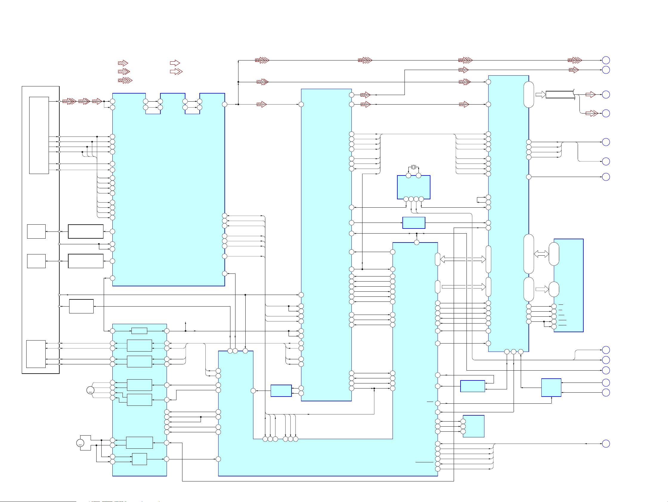
7-1. BLOCK DIAGRAM – RF SERVO Section –
• SIGNAL PATH
: CD PLAY
: DVD PLAY
: SACD PLAY
RF
1
63
DVDRFP
RFSIN
ATOP
ATON
62
61
: AUDIO
: VIDEO
117
RFIN
64
FNP
AIP
59
AIN
60
FNN
535254
DIP
55
DIN
RFAC
57
50
RFAC
DOUT
PCMD
32, 30, 27, 24
HDB0 – HDB7
66
160
MDAT
44, 41, 39, 35,
AV DATA BUS
WARFI
CDDOUT
SD0 – SD7
(for AUDIO SYSTEM)
SD0 – SD7
(for VIDEO SYSTEM)
A
B
C
D
(Page 29)
(Page 29)
(Page 29)
(Page 31)
DETECTOR
OPTICAL PICK-UP
BLOCK
(TDP022W)
LASER
CD LD
DIODE
(FOR CD)
LASER
DVD LD
DIODE
(FOR DVD)
INLIM
FCS+
FCS–
2AXIS
DEVICE
FOCUS/
COIL
TRK+
TRK–
TRACKING
A
B
C
D
F
E
PD
SW
AUTOMATIC POWER
CONTROL (FOR CD)
AUTOMATIC POWER
CONTROL (FOR DVD)
LASER DIODE
M1
(SPINDLE)
SELECT
Q301
M2
(SLED)
MM
D
Q002
Q001
CBA
MM
A2
3
B2
4
C2
5
D2
6
18
CD E
17
CD F
B
12
A
A
11
B
D
10
C
C
9
D
B
16
CD A
A
15
CD B
D
14
CD C
C
13
CD D
22
CDLD
24
CDPD
DVDPD
23
DVDLD
21
V125
36
FOCUS/TRACKING COIL DRIVER,
SPINDLE, SLED MOTOR DRIVER
36 48
37 1
34 3
35 4
32
31
30
29
27
28
47
46
IC501
BUFFER
FOCUS COIL
DRIVE
TRACKING COIL
DRIVE
SLED MOTOR
DRIVE
SLED MOTOR
DRIVE
SPINDLE MOTOR
DRIVE
BUFFER
CD/DVD/SACD RF AMP,
FOCUS/TRACKING ERROR AMP
POWER SAVE
MUTE12
MUTE34
MUTE5
TSD-M
IC001
4042
7
10
39
19
20
21
22
13
45
(1.65V)
FF
FR
TF
TR
AVC
SDATA
SCLK
SDEN
MIRR
LDON
FF
FR
TE
FE
7
8
44
43
97
60
63
73
62
47
46
48
39
40
42MNTR
27
26
76 31
LDSEL
FCS JMP 1
FCS JMP 2
SLED B
SLED A
DSAVE
MUTE 2D
SP ON
TSD
FG
28
LD ON
SLED
DATA_RF
CLK_RF
SDEN
MIRR
INLIM
61
TE
FE
PI
TE
FE
PI
CLK_RF
DATA_RF
82
83
SDATA RF
AMP
IC402 (1/2)
SDEN
2
SDEN
SDCLK RF
BCLK
LRCK
C2PO
WDCK
WFCK
SBSO
DIGITAL SIGNAL PROCESSOR,
DIGITAL SERVO PROCESSOR
SSTP
26
41
TE
40
SE
FE
39
43
RFDC
VC
38
CE
42
FF
33
FFDR
FR
34
FRDR
TF
31
TFDR
TR
32
TRDR
SFDR
29
SRDR
30
MIRR
PI
FE
TE
67PI66
65
FE
TE
MECHANISM
CONTROLLER
IC301 (1/2)
EXCK
IC401
XTAI
MDP
XRST
MD2
SCOR
DATA
CLOK
XLAT
SENS
SQSO
SQCK
LOCK
GFS
MUTE
COUT
SCLK
FOK
MIRR
LRCK
65
C2PO
14
GSCOR
17
WFCK
10
SBSO
79
EXCK
80
SCOR
CLOCK
GENERATOR
IC303
10 3
71
25
2
63
15
4
6
5
7
76
77
24
13
3
19
8
22
20
3
26
49
50
27
9
52
54
75
71
59
30
72
74
29
DOCTR/
ISBTEST
SCOR
DATA CD
CLOK CD
LAT CD
SENS CD
SQSO
SQCK
LOCK CD
GFS CD
MUTE CD
COUT CD
SCLK CD
FOK CD
MIRR
IC703 (2/2)
7 8
XTI
SO2
MO1
13 9
27M
BUFFER
X302
27MHz
XTO
SO3
SO1
768FS
98
XDRST
XRD
XWR
XCS DVD
INT0 DVD
INT1 DVD
GFS DVD
XRST DVD
JIT OFFSET
SACD/DVD
EEP RDY
EEP SI
EEP CLK
EEP CS
SDIN DSD
SDOUT DSD
SCK DSD
XMSLAT
READY DSD
MUTE DSD
JIT
14-21
D0 – D7
89-96
A0 – A7
85
84
12
22
23
58
25
45
64
77
6
5
100
99
47
46
24
51
48
53
BCLK
67
BCLK
LRCK
C2PO
GSCOR
WFCK
SBSO
EXCK
SCOR
COMPARATOR
IC703 (1/2)
5
SDA
6
SCL
7
WP
MSDATO
MSDATI
MSCK
XMSLAT
SHRRDY
SHRMUT
158
BCK
163
LRCK
155
C2PO
146
GSCOR
151
WFCK
148
SBIN
147
EXCK
150
SCOR
DVD DECODER
167
XTA1
169
XTA2
170
XTAL
137
MDIN2
135
SPO
D0 – D7
172-176, 1, 2, 4
A0 – A7
5, 7, 9-14
17
XRD
18
XWR
19
XCS
20
XINT0
21
XINT1
107
GFS
164
XRST
EEPROM
IC302
IC701
AEP0
109
XDCK
XSAK
HDB8
XSHD
MNT2
MDB0 – MDB9,
MDBA – MDBF
MA0 – MA9
WE
XMOE
XRAS
XCAS
XSRQ
MNT1
53
92
48
46
26
49
93
66-69, 71, 73-75, 96, 97,
79, 80, 82-87,
76
94
78
95
XDCK
XSAC
SDEF
XSHD
2-5, 7-10,
99, 101, 102, 104-106
89, 91
21-24,
17
33
18
34
35
SACD/DVD
SELECT
IC814
41-44, 46-49
27-32
WE
OE
RAS
UCAS
LCAS
XMSLAT, SHRRDY, SHRMUT
XDCK, XSAC, SDEF, XSHD
(for AUDIO SYSTEM)
XDCK, XSAC,, SDEFF
(for VIDEO SYSTEM)
WCK
I/O0 – I/O15A0 – A9
16Mbit
D-RAM
IC706
768FS
27M
XRST_DSD
XSRQ
XSRQ-ZIVA
MSDATO, MSDATI, MSCK,
E
F
G
H
J
K
L
M
I
(Page 29)
(Page 31)
(Page 29)
(Page 29)
(Page 31)
(Page 29)
(Page 29)
(Page 31)
(Page 29)
2828
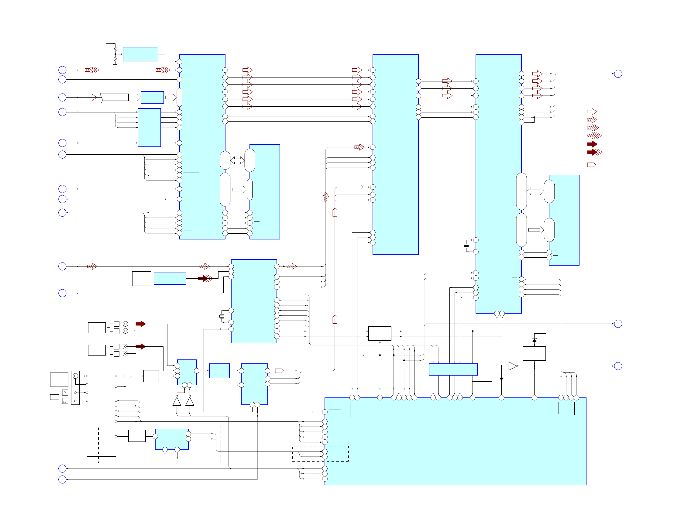
7-2. BLOCK DIAGRAM – AUDIO (DSP) Section –
D5V
REFERENCE VOLTAGE
GENERATOR
(Page 28)
(Page 28)
(Page 28)
(Page 28)
(Page 28)
(Page 28)
(Page 28)
(Page 28)
(Page 31)
(Page 28)
(Page 31)
(Page 31)
(Page 30)
WARFI
A
WCK
G
SD0 – SD7
C
SDEF, XSHD,
XDCK, XSAK
E
768FS
H
MSDATO, MSDATI, MSCK,
XMSLAT, SHRRDY, SHRMUT
M
XRST_DSD
J
XSRQ
K
TDOSA, TDISA,
TCK, TMS, TRST
N
CDDOUT
B
SPDIF
O
COAXIAL
FM
75Ω
AM
AV0 – AV2
P
RSTAD
S
AV DATA BUS
J205 (1/4)
VIDEO 1
AUDIO IN
J206 (1/3)
VIDEO 2
AUDIO IN
FM/AM TUNER PACK
FM ANT
L-CH
GND
R-CH
AM ANT
GND
DI
DO
CK
CE
TUNED
FM-DET
(AEP, UK, Russian)
L
R
L
R
XDCK
XSAK
SDEF
XSHD
R-CH
TUDI
TUDO
TUCLK
TCE
TUN
DET AMP
IC402 (2/2)
LEVEL SHIFT
LEVEL SHIFT
OPTICAL
DIGITAL IN
VIDEO 2
R-CH
R-CH
Q201
IC812
IC813
MSDATO
MSDATI
MSCK
XMSLAT
SHRRDY
SHRMUT
TDOSA
TDISA
TCK
TMS
TRST
OPTICAL RECEIVER
AMP
Q221
4
X201
4.332MHz
IC204
Q205
MUX
XI XO
13 14
127
126
123
169 – 176
166
167
168
165
11
6
4
3
2
7
10
9
164
29
27
26
30
31
AUDIO INPUT
SELECTOR
IC202
2
Y2
1
Y0
5
Y1
10 9
AV2
RDATA
RCLK
WAVRB
WARFI
WCK
SD0 – SD7
SDCK
XSAK
SDEF
XSHD
DSD DECODER
MCKI
MSDATO
MSDATI
MSCK
XMSLAT
MSREADY
SMUTE
XRST
XSRQ
TDO
TDI
TCK
TMS
TRST
Y
AB
Q206
AV0
2
16
RDS DECODER
IC801
12.288MHz
3
RDSD
RDSC
IC201
PHREFO
EXCKO1
X600
DSAL
DSAR
DSAC
DSALFE
DSALS
DSARS
DQ0 – DQ7A0 – A11
XWE
XRAS
XCAS
DCKE
DCLK
LOW-PASS
FILTER
IC603
64
66
69
71
74
76
62
13
134-131
139-136,
162-159, 157-154,
152, 151, 149, 148
143
145
144
142
141
5
DIN2
4
DIN1
3
DIN0
22
XIN
21
XOUT
20
XMCK
R-CH
9, 11, 12
2, 3, 5, 6, 8,
A0 – A11
19-24, 27-32
15
WE
17
RAS
16
CAS
34
CKE
35
CLK
DIGITAL AUDIO
INTERFACE
IC606
A/D CONVERTER
IC602
1
DOUT
LIN
BCK
LRCK
5
RIN
SYSCLK
16 6
DQ0 – DQ7
16Mbit
SD-RAM
IC808
16
DATA
13
CKOUT
14
BCK
15
LRCK
36
DI
35
DO
38
CL
37
CE
17
XSTATE
48
XMODE
34
ERROR
24
AUDIO
15
14
13
RSTB
(AEP, UK, Russian)
EXID2
BCK2
LRCK2
PLOCK
DIGDI
DIGCLK
CSDIR
XST
RSTDIR
DO
EXIMCK
EXILRCK
TUDI
TUDO
TUCLK
TCE
TUN
RDSD
RDSC
AV0
AV1
AV2
EXID1
EXIBCK
33
52
54
55
53
51
88
94
95
96
48
EXID1
EXIMCK
EXIBCK
EXILRCK
AD-RST
TUN-DI
TUN-DO
TUN-CLK
TUN-CE
TUNED
RDS-DATA
RDS-CLK
AV-SEL0
AV-SEL1
AV-SEL2
EXID2
BCK2
LRCK2
98
65
DFIL RST2
DF-SYNC
63
DSIFL
64
DSIFR
65
DSICT
66
DSISW
67
DSISL
68
DSISR
62
DSBCKF
52
MCK
58
EXID1
59
EXIMCK
55
EXIBCK
56
EXILRCK
57
EXID2
29
BCK2
28
LRCK2
79
INIT
78
SYNC
SELEXT
77
ENABLE
SWITCH
Q908 – 910
97
DF-SW
F2FLREX1
F2CSWEX2
F2LRCK
DIGITAL AUDIO
PROCESSOR
IC612
DO
DIGDI
7
25DI8
DIG-DI
F2SLR
CKOUT
F2BCK
CSDIR
DIGCLK
20
DIG-CLK
47
46
45
49
43
44
RSTDIR
24
DIR-CE
DIR-XMODE
X601
13.5MHz
DIGDI
DIGCLK
XST
PLOCK
LEVEL SHIFT
IC900
22
18
6
DSP-DO
DIR-XST
DIR-ZERO
SYSTEM CONTROLLER
IC901 (1/3)
15
17
DSP-HACN
DSP-GP9
18
SDI1
30
SDI2
114
SDI3
22
KFSIO
17
BCKI1
15
LRCKI1
SIGNAL PROCESSOR
9
MCLK1
12
MCLK2
33
HDIN
34
HCLK
35
HDOUT
32
HACN
68
GP9
19
DIR-ERR
SCKOUT
DIGITAL AUDIO
IC607
EXLOCK69GP8
59
D903
23
DIR-AD
SDO4
SDO1
SDO2
SDO3
BCKO
LRCKO
GP10
CS0
WE0
PM
HCS
BST
XRST
Q903
26
23
24
25
14
20
19
67
D0 – D15A0 – A15
44
45
113
36
56
D4
D1
D2
D3
SCK
BCKO
LRCKO
98, 80-77, 75-72
108, 107, 105-102, 99
112, 110, 109,
97-92, 82-85, 66-64
41
17
POWER ON
MUTING
Q490, 492
28
DAMP-MUTEN
RSTDSP
12V
D490
2
D0 – D15
7-10, 13-16,
29-32, 35-38
S-RAM
IC604
A0 – A15
5-1, 44-42,
27-24, 21-18
OE
WE
PM
HCS
BST
PM
13 14 16 12
BST
HCS
DSP-CS
DSP-PM
D1 – D4, SCK,
BCKO, LRCKO
• R-ch is omitted due
to same as L-ch.
• SIGNAL PATH
DIGDI, DIGCLK
NSMUTE
RSTDSP
DSP-BST
DSP-RST
HCD-S550/S880
(Page 30)
Q
: AUDIO
: CD PLAY
: DVD PLAY
: SACD PLAY
: AUX IN
: OPTICAL
DIGITAL IN
: TUNER
(Page 30)
T
(Page 30)
R
2929

HCD-S550/S880
7-3. BLOCK DIAGRAM – AUDIO OUT, PANEL Section –
D/A CONVERTER
3
SDTI
1
MCLK
2
BICK
4
LRCK
8
CDTI
7
CCLK
IC802
DAT
CLK
CS
RST
OSC0
OSC1
VOLUME
S201
SCAN SELECT
INTERLACE
SELECTABLE
IC608
AOUTL+
AOUTL–
AOUTR+
AOUTR–
PDN
65
63
62
61
60
58
59
C818, R840
KEY0, KEY2
KEY INPUT
DETECT
IC903, 904
WAKE UP
DETECT
Q907
SIRCS DETECT
Q906
ROTARY
ENCODER
S800
12
11
10
9
CSN
OSC
I2CDATA
I2CCLK
I2HLP
(Page 29)
(Page 29)
(Page 29)
(Page 29)
(Page 32)
(Page 31)
(Page 31)
• SIGNAL PATH
: AUDIO
DIGDI, DIGCLK
T
RSTAD
S
D1 – D4, SCK,
BCKO, LRCKO
Q
NSMUTE
R
DISC IN
X
I2CDATA,
I2CCLK, I2HLP
W
ZIVARESET
V
FLUORESCENT
INDICATOR TUBE
FL801
D4
SCK
BCKO
LRCKO
DIGDI
DIGCLK
S801 – 806,
S821 – 825
DISC LOADING
DETECT
Q913
REMOTE CONTROL
FL DRIVER
5 – 39
S1 – S35
40 – 51
G1 – G12
4
AD1
3
AD2
RECEIVER
IC801
LOW-PASS
FILTER
IC610
60
57
61
56
82 – 84
93
92
85
86
49
3
5
100
4
MUTING
Q207, 208
SYSTEM CONTROLLER
FL-DATA
FL-CLK
FL-CS
FL-MUTE
KEY0 – KEY2
WAKE
SIRCS
EN-A
EN-B
PROG SW
I2C-DATA
I2C-CLK
I2HLP
CQ-RST
IC901 (2/3)
MUTING CONTROL
Q900
HPSW
HP-MUTE
AU-MUTE
DAS-CS
DAMP-DATA
DAMP-CLK
CS1
CS2
CS3
DAMP-RST
DAMP-MUTING
DIP-RST
DIP-OCP
X1
X2
L
R
J205 (2/4)
VIDEO 1
AUDIO OUT
64
46
47
32
39
38
1
2
29
30
31
26
27
43
44
X901
20MHz
AU-MUTE
DAS-CS
HP-SW
HP-MUTE
AU-MUTE
DAS-CS
SCDT
SHIFT
LATCH1
LATCH2
LATCH3
INIT
PGMUTE
D1
SCK
BCKO
LRCKO
SCDT
SHIFT
LATCH1
INIT
PGMUTE
D2
SCK
BCKO
LRCKO
SCDT
SHIFT
LATCH2
INIT
PGMUTE
D3
SCK
BCKO
LRCKO
SCDT
SHIFT
LATCH3
INIT
PGMUTE
STREAM PROCESSOR
IC305
43
DATA
64
XFSIIN
44
BCK
45
LRCK
38
SCDT
37
SCSHIFT
36
SCLATCH
41
INIT
40
PGMUTE
39
NSPMUTE
STREAM PROCESSOR
IC308
43
DATA
64
XFSIIN
44
BCK
45
LRCK
38
SCDT
37
SCSHIFT
36
SCLATCH
41
INIT
40
PGMUTE
39
NSPMUTE
STREAM PROCESSOR
IC310
43
DATA
64
XFSIIN
44
BCK
45
LRCK
38
SCDT
37
SCSHIFT
36
SCLATCH
41
INIT
40
PGMUTE
39
NSPMUTE
OUTL1–
OUTL2–
OUTR1–
OUTR2–
OUTL1+
OUTL2+
OUTR1+
OUTR2+
XFSOIN
FSOCKO
FSOI
XFSOUT
XFSOIN
OUTR1+
OUTR2+
OUTL1+
OUTL2+
FSOI
XFSOUT
XFSOIN
OUTL1+
OUTL2+
OUTR1+
OUTR2+
FSOI
OVER LOAD
DETECT
Q109, 110
OVER LOAD
DETECT
Q103, 104
OVER LOAD
DETECT
Q105, 106
OVER LOAD
DETECT
Q111, 112
OVER LOAD
DETECT
Q107, 108
OVER LOAD
DETECT
Q101, 102
HP-SW
32V
J401
SPEAKER
FAN
Y
(+)
(–)
(+)
(–)
(+)
(–)
(+)
(–)
(+)
(–)
(+)
(–)
(Page 32)
J900
PHONES
FRONT
L
FRONT
R
CENTER
WOOFER
REAR
L
REAR
R
21
18
7
4
24
15
10
1
28
73
74
77
28
10
1
24
15
74
77
28
24
15
10
1
74
BUFFER
49.152MHz
IC300
X300
HADPHONE
AMP
IC401
HP-MUTE
CONTROL
POWER AMP
IC301
6
INA
16
INB
ENA
ENB
7 17 8 18
POWER AMP
IC304
6
INA
16
INB
ENA
ENB
7 17 8 18
POWER AMP
IC307
6
INA
16
INB
ENA
ENB
7 17 8 18
POWER AMP
IC306
6
INA
16
INB
ENA
ENB
7 17 8 18
POWER AMP
IC309
6
INA
16
INB
ENA
ENB
7 17 8 18
POWER AMP
IC311
6
INA
16
INB
ENA
ENB
7 17 8 18
PROTECT DETECT
Q113, 114
MUTING
Q902
D181 D192
OUTA
19
OUTB
DIAGA
DIAGB
OUTA
19
OUTB
DIAGA
DIAGB
OUTA
19
OUTB
DIAGA
DIAGB
OUTA
19
OUTB
DIAGA
DIAGB
OUTA
19
OUTB
DIAGA
DIAGB
OUTA
19
OUTB
DIAGA
DIAGB
MUTING
Q900, 901
POWER ON
MUTING
9
D105
9
D102
9
D103
9
D106
9
D104
9
D101
Q192
3030
Loading...