


CFS-1085-S
Table of contents
 Loading...
CFS-1085S
SERVICE MANUAL
Ver 1.0 2001.10
Model Name Using Similar Mechanism CFS-1065S
Tape Transport Mechanism Type MF-1055-117
SPECIFICATIONS
• Frequency range
FM: Saudi Arabia: 87.5–107 MHz/
Other countries: 87.5–108 MHz
MW: Saudi Arabia: 530–1 605 kHz/
Other countries: 530-1 611 kHz/
SW1: 2.3–7 MHz/SW2: 7–22 MHz
• IF FM: 10.7 MHz,
MW/SW: 455 kHz
• Antennas FM/SW: Telescope/
MW: Built-in ferrite bar
• Recording system 4-track, 2-
channel stereo
• Frequency response 80–10 000Hz
• Speakers Woofer: 10 cm (4 inches)
dia., 6 Ω,cone type/Tweeter: 2 cm
(13 ⁄16 inch) dia.
• Input CD/TV LINE IN jacks
(phono jacks), sensitivity 0.436 V,
input impedance 47 kΩ
• Output Headphones jack (stereo
minijack), for 6–32 Ω impedance
headphones
• Maximum Power output
10 W
E Model
• Battery life
FM Recording: Sony R20P: Approx.
5 hours/Sony LR20 alkaline:
Approx. 10 hours
Playback: Sony R20P: Approx. 1.5
hours/Sony LR20 alkaline:
Approx. 3 hours
• Power requirements
110–120V/220–240 V AC
selectable, 50/60 Hz
9V DC, six R20 (size D) batteries
• Power consumption
AC 14 W
• Dimensions Approx. 579 x 206 x
197 mm (w/h/d) (22 7 ⁄8 x 8 1 ⁄8 x
7 7 ⁄8 inches) incl. projecting parts
and controls, not incl. handle
• Mass Approx. 4.6 kg (10 lb 2 oz)
incl. batteries
• Supplied accessory AC power
cord (1)
Design and specifications are
subject to change without notice.
9-873-310-01
2001J0200-1
© 2001.10
RADIO CASSETTE-CORDER
Sony Corporation
Personal Audio Company
Published by Sony Engineering Corporation

CFS-1085S
TABLE OF CONTENTS
1. GENERAL .......................................................................... 3
2. DISASSEMBLY
2-1. Power Board ......................................................................... 4
2-2. LED Board, GE SW Board, MEGA BASS Board................ 5
2-3. MAIN Board, MIC Board, VOL Board................................ 5
2-4. Mechanism Deck, Tuner Board ............................................ 6
2-5. Record/Playback Head (HRP101), Erase Head (HE301),
Belt, Motor (M601) ............................................................. 6
2-6. Dial Pointer Installation ........................................................ 7
3. ADJUSTMENT .................................................................. 8
4. DIAGRAMS
4-1. Circuit Boards Location ...................................................... 12
4-2. Block diagrams ................................................................... 13
4-3. Printed Wiring Board – Main Section –..............................14
4-4. Schematic Diagram – Main Section – ................................ 15
4-5. Schematic Diagram – Tuner Section –................................ 16
4-6. Printed Wiring Board – Tuner Section – ............................. 17
4-7. IC Block Diagrams ...........................................................18
5. EXPLODED VIEWS
5-1. Rear Cabinet Section........................................................... 20
5-2. Front Panel Section ............................................................. 21
5-3. Speaker Section................................................................... 22
5-4. Mechanism Deck Section (1).............................................. 23
5-5. Mechanism Deck Section (2).............................................. 24
6. ELECTRICAL PARTS LIST .................................25
SAFETY-RELATED COMPONENT WARNING !!
COMPONENTS IDENTIFIED BY MARK ! OR DOTTED LINE
WITH MARK ! ON THE SCHEMATIC DIAGRAMS AND IN
THE PARTS LIST ARE CRITICAL TO SAFE OPERATION.
REPLACE THESE COMPONENTS WITH SONY PARTS
WHOSE PART NUMBERS APPEAR AS SHOWN IN THIS
MANUAL OR IN SUPPLEMENTS PUBLISHED BY SONY.
2
SECTION 1
GENERAL
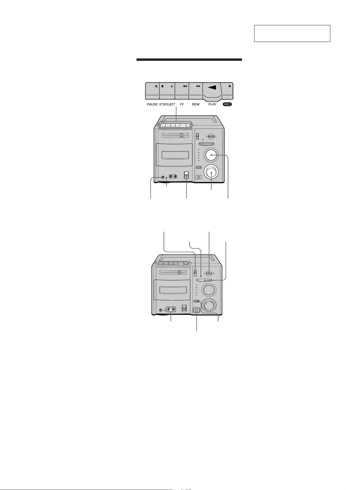
Location of controls
CFS-1085S
This section is extracted from
instruction manual.
OPR/
BATT
PHONES
FUNCTION
BAND FINE TUNING
FM STEREO
CD/TV
LINE IN
VOLUME
SOUND SELECT
TUNING
MAXI BASS
MIC
3
CFS-1085S
)
Note: Disassemble the unit in the order as shown below.
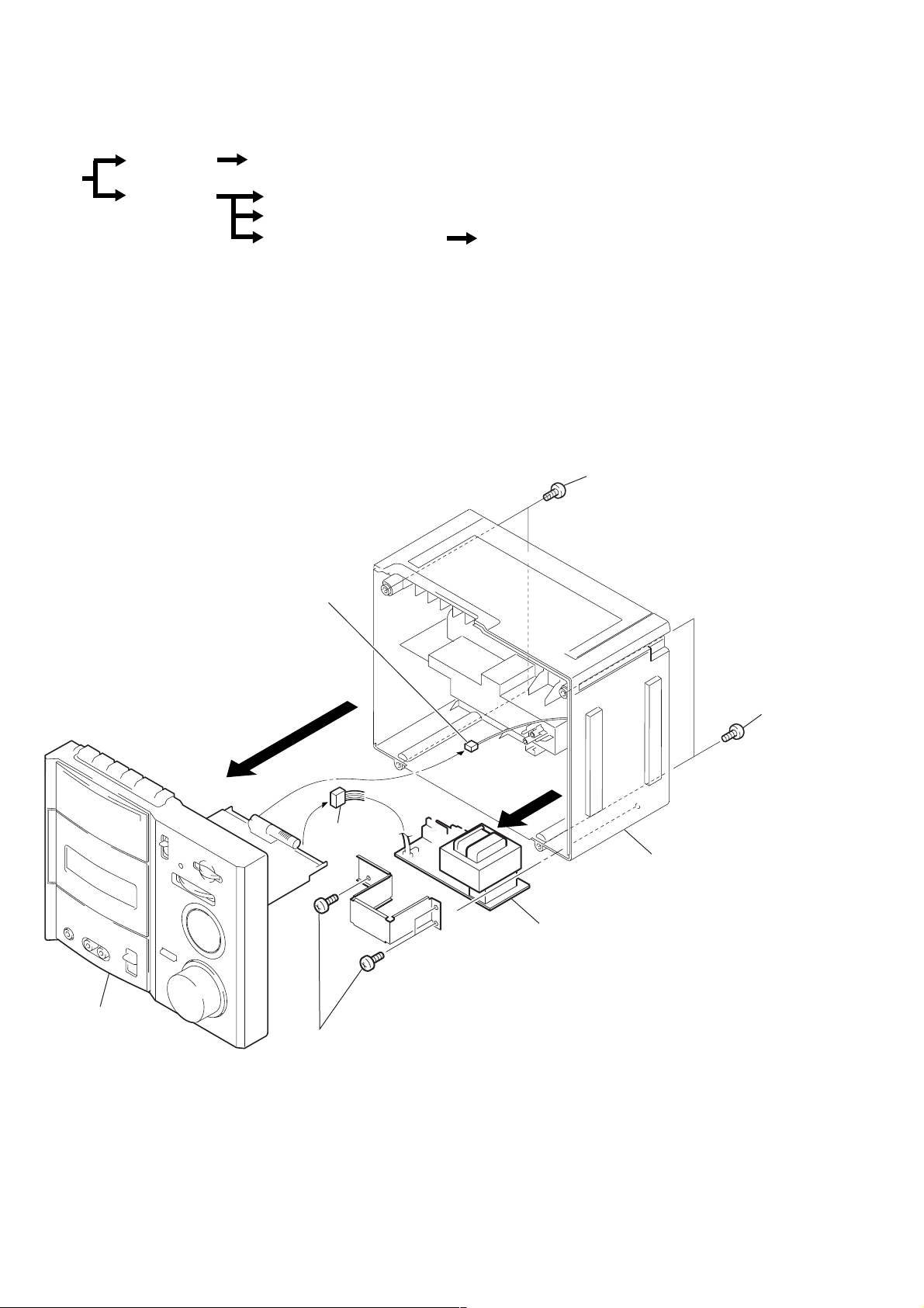
SECTION 2
DISASSEMBLY
Cabinet (rear)
Power board
Set
Cabinet (front)
LED board, GE SW board, Mega bass SW board
Main board, MIC board, VOL board
Mechanism deck, Tuner board
Note: Follow the disassembly procedure in the numerical order given.
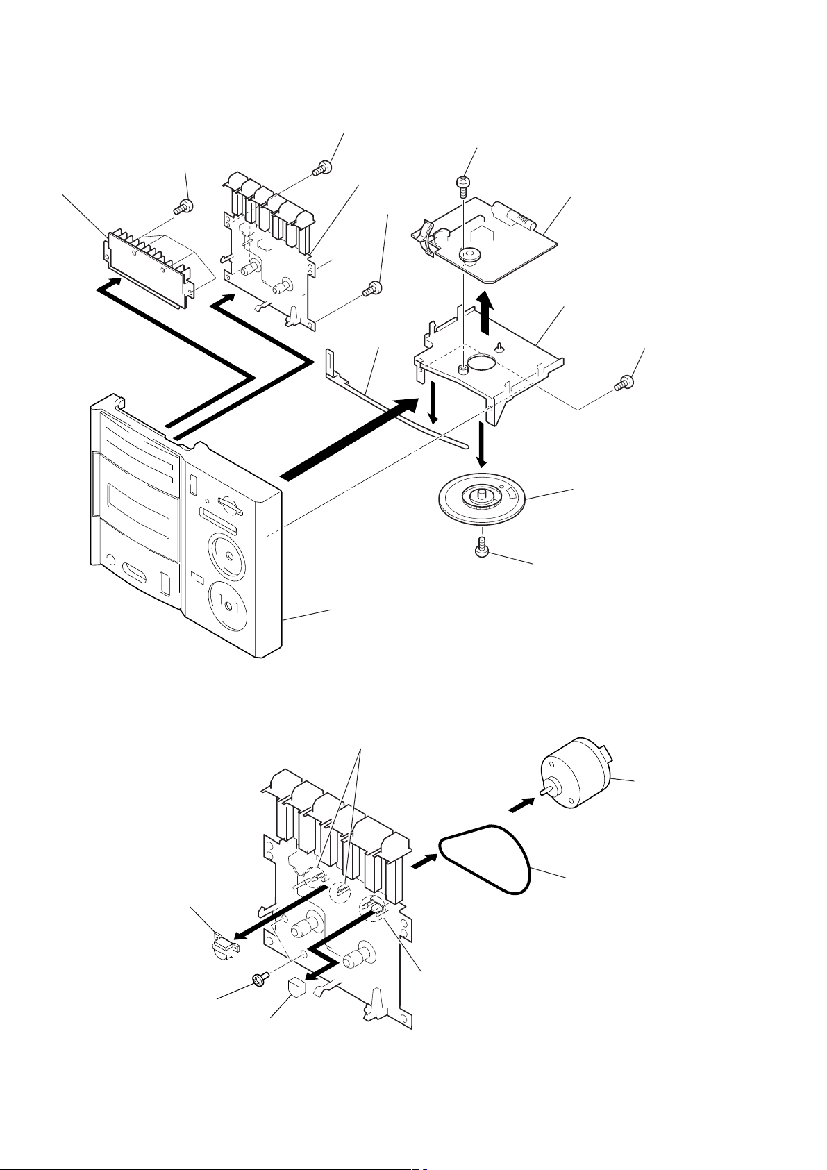
2-1. POWER BOARD
Tuner board
4
(CNP1)
Record/playback head (HRP101), Erase head (HE301),
Belt, Motor (M601)
Screws (3X4)
1
Cabinet (front)
2
Main board
3
(CNP305)
Screws (3X10)
5
6
Power board
Cabinet (rear)
Screws (3X4
1
4
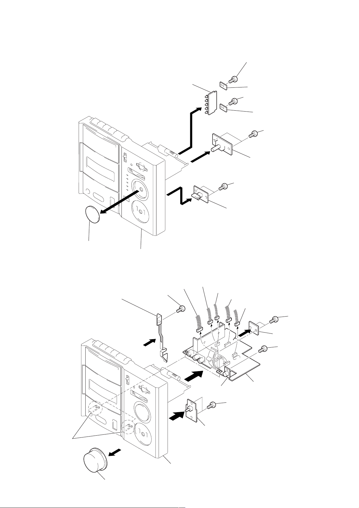
2-2. LED BOARD, GE SW BOARD, MEGA BASS SW BOARD
Screw (2.6X8)
1
CFS-1085S
Knob (job)
5
Cabinet (front)
LED board
2
7
4
Bracket (B) board
Screw (2.6X8)
1
Bracket (B) board
Screws (2.6X8)
3
GE SW board
Screws (2.6X8)
6
Mega bass SW board
2-3. MAIN BOARD, MIC BOARD, VOL BOARD
Screw (2.6X8)
1
2
6
Lever (rec)
Claws
qd
CNP306
8
qg
7
CNP303
9
MIC board
VOL board
CNP302
0
qf
CNP304
qa
CNP301
qs
4
Main board
Screws (2.6X8)
Screws (2.6X8)
3
Bracket (B) board
Screw (2.6X8)
5
Knob (VOL)
Cabinet (front)
5
CFS-1085S
)
2-4. MECHANISM DECK, TUNER BOARD
Screws (2.6X8)
5
Pointer chassis
Screws (2.6X8)
3
Mechanism deck
Screws (2.6X8)
3
Screw (3X8)
0
Tuner board
6
4
qa
Pointer
9
2
8
Cabinet (front)
Chassis
Knob (tun)
Screw (2.6X5)
7
2-5. RECORD/PLAYBACK HEAD (HRP101), ERASE HEAD (HE301), BELT, MOTOR (M601)
Screws (2.6X8
1
Claws
1
Motor
(M601)
Record / playback head
(HRP101)
Screws (2.6X5)
5
2
Erase head
(HE301)
4
7
3
6
Belt
Claws
6
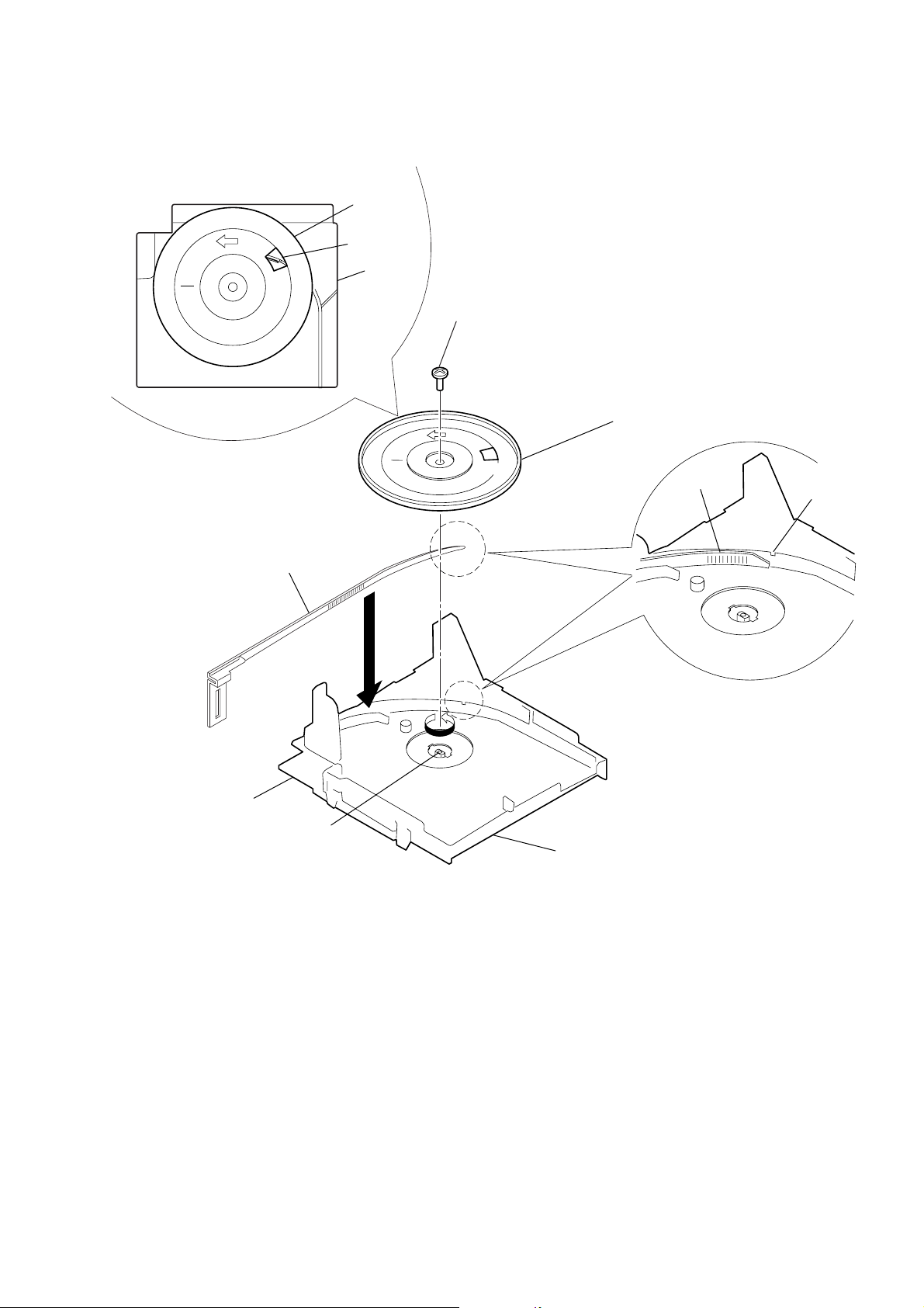
2-6. DIAL POINTER INSTALLATION
CFS-1085S
Knob (tune)
MIN
(Fig-2)
Pointer
Window
Chassis
2
Screw (2.6X5)
5
MIN
Knob (tune)
Pointer
Notch
(Fig-1)
Tuner board
PVC shaft
1
Chassis
1 Turn the PVC shaft fully counterclokwise.
2 Place the pointer in the chassis groove.
3 Line up the tip of the pointer with the notch in the chassis.
(Fig-1)
4 Attach so that the knob (T une) is at the position shown in
Fig-2.
5 Fasten the knob (tune) to the PVC shaft with the screw.
7
CFS-1085S
SECTION 3
ADJUSTMENTS
3-1. MECHANICAL ADJUSTMENTS
PRECAUTION
1. Clean the following parts with a denatured-alcohol-moistened
swab :
record/playback head pinch roller
erase head rubber belts
capstan
2. Demagnetize the record/playback head with a head demagnetizer. (Do not bring the head demagnetizer close to the erase
head.)
3. Do not use a magnetized screwdriver for the adjustments.
4. The adjustments should be performed with the rated power supply voltage (9V) unless otherwise noted.
1.Torque Measurement
Mode T orque Meter Meter Reading
2.95 – 6.86 mN•m
Playback CQ-102C (30 – 70 g•cm)
(0.42 – 0.97 oz•inch)
0.15 – 0.53 mN•m
Back Tension CQ-102C (1.5 – 5.5 g•cm)
(0.021 – 0.076 oz•inch)
Rewind
Fast Forward
CQ-201B (55 – 135 g•cm)
5.4 – 13.2 mN•m
(0.77 – 1.87 oz•inch)
3-2. ELECTRICAL ADJUSTMENTS
TAPE SECTION
z Switch location
FUNCTION switch................. TAPE (RADIO OFF)
SOUND SELECT.................... FLAT
VOLUME................................. mechanical center
MEGA BASS............................ OFF
0dB = 0.775 V
Test T ape
Type Signal Used for
WS-48B 3kHz, 0dB Tape Speed Adjustment
2. T ape T ension Measurement
Mode Torque Meter Meter Reading
FWD CQ-403A more than 100g (3.53 oz)
8
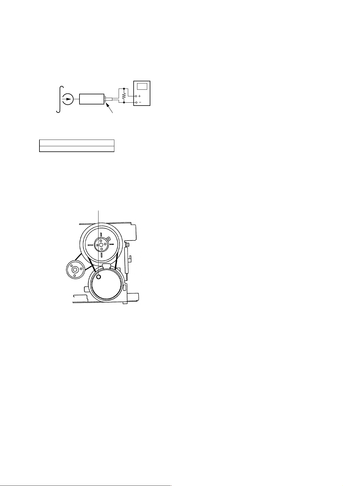
Tape Speed Adjustment
y
Procedure :
Mode : playback
CFS-1085S
test tape
WS-48B
(3kHz, 0dB)
set
digital frequenc
Ω
32
phones jack
counter
Adjustment V alues :
Digital frequencycounter
2,910 to 3,090Hz
Frequency difference between the begining and the end of the
tape should be within 1% (30Hz)
Adjustment V alues :
tape speed adjustment
control inside motor
9
CFS-1085S
c
r
c
Adjustment Location : Mechanism deck
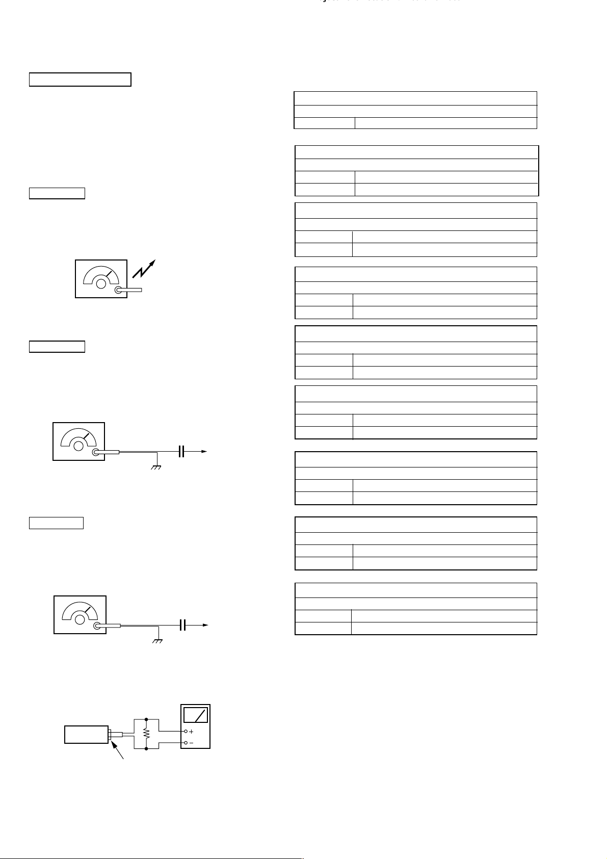
TUNER SECTION
z Switch location
FUNCTION switch................ TAPE (RADIO OFF)
SOUND SELECT.................. FLAT
VOLUME.............................. mechanical center
MEGA BASS......................... OFF
TUNER SECTION
MW Section
Procedure :
BAND Switch : MIN
FINE TUNE control : mechanical center
AM RF signal
generator
30% amplitude modulation by 400Hz
signal.
Output level : as low as possible
SW Section
Procedure :
BAND Switch : SW1, SW2
FINE TUNE control : mechanical center
AM RF signal
generator
30% amplitude modulation by
400Hz signal.
Output level : as low as possible
Put the lead-wire
antenna close to
the set.
12PF
telescopi
antenna
terminal
( ) : Saudi Arabia model
AM IF ADJUSTMENT
Adjust for a maximum reading on level meter.
T1 455kHz
MW FREQUENCY COVERAGE ADJUSTMENT
Adjust for a maximum reading on level meter.
L4 520kHz
CT4 1,680kHz
MW TRACKING ADJUSTMENT
Adjust for a maximum reading on level meter.
L3 620kHz
CT3 1,400kHz
SW1 FREQUENCY COVERAGE ADJUSTMENT
Adjust for a maximum reading on level meter.
L6 2.2MHz
CT6 7.3MHz
SW1 TRACKING ADJUSTMENT
Adjust for a maximum reading on level meter.
L5 2.2MHz
Confirmation 7.3MHz
SW2 FREQUENCY COVERAGE ADJUSTMENT
Adjust for a maximum reading on level meter.
L8 6.8MHz
CT8 22.5MHz
SW2 TRACKING ADJUSTMENT
Adjust for a maximum reading on level meter.
L7 6.8MHz
Confirmation 22.5MHz
FM Section
Procedure :
BAND Switch : FM
FINE TUNE control : mechanical center
FM RF signal
generator
0.01µF
22.5kHz frequency deviation by
1kHz signal.
Output level : as low as possible
level mete
32Ω
set
J301 (phones)
telescopi
antenna
terminal
• Repeat the procedures in each adjustment several times, and the
frequency coverage and tracking adjustments should be finally
done by the trimmer capacitors.
FM FREQUENCY COVERAGE ADJUSTMENT
Adjust for a maximum reading on level meter.
L2 86.5MHz (87.35MHz)
CT2 109.5MHz (107.8MHz)
FM TRACKING ADJUSTMENT
Adjust for a maximum reading on level meter.
L1 86.5MHz (87.35MHz)
CT1 109.5MHz (107.8MHz)
10
Loading...