


CCD-TR417E
Sony CCD-TR417E, CCD-TR427E, CCD-TR617E, CCD-TR717E, CCD-TR918E Service Manual
...
CCD-TR317E/TR417E/TR427E/TR617E/TR717E/TR918E
CCD-TRV37E/TRV47E/TRV48E/TRV57E/TRV67E/TRV87E
RMT-708
AEP Model
East European Model
North European Model
Russian Model
CCD-TR417E/TR427E/TR617E/TR717E/
TR918E/TRV37E/TRV48E/TRV57E/
TRV67E/TRV87E
UK Model
CCD-TR417E/TR427E/TR717E/
TR918E/TRV37E/TRV48E/
TRV57E/TRV67E/TRV87E
E Model
Hong Kong Model
Australian Model
Chinese Model
CCD-TR317E/TRV47E/TRV57E/
TRV67E/TRV87E
Tourist Model
CCD-TRV47E/TRV57E/TRV67E/TRV87E
SERVICE MANUAL
VIDEO CAMERA RECORDER
CCD-TR717E/TR918E/TRV67E/TRV87E
MICROFILM
B201 MECHANISM
For MECHANISM ADJUSTMENT, refer to
the “8mm Video MECHANICAL
ADJUSTMENT MANUAL
” (9-973-801-11).
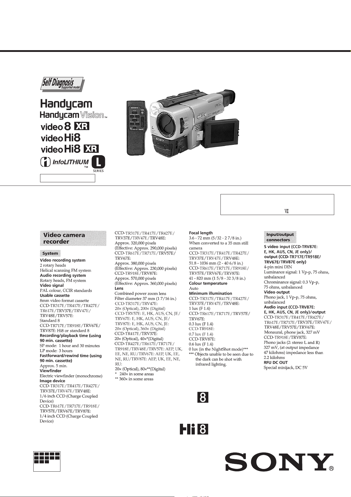
SPECIFICATIONS
Photo : CCD-TRV87E
VIDEO CAMERA RECORDER
CCD-TR317E/TR417E/TR427E/TR617E/
TRV37E/TRV47E/TRV48E/TRV57E
— Continued on next page —
Ver 1.1 2000. 11
— 2 —
SAFETY-RELATED COMPONENT WARNING!!
COMPONENTS IDENTIFIED BY MARK 0 OR DOTTED LINE WITH
MARK 0 ON THE SCHEMATIC DIAGRAMS AND IN THE PARTS
LIST ARE CRITICAL TO SAFE OPERATION. REPLACE THESE
COMPONENTS WITH SONY PARTS WHOSE PART NUMBERS
APPEAR AS SHOWN IN THIS MANUAL OR IN SUPPLEMENTS
PUBLISHED BY SONY.
1. Check the area of your repair for unsoldered or poorly-soldered
connections. Check the entire board surface for solder splashes
and bridges.
2. Check the interboard wiring to ensure that no wires are
"pinched" or contact high-wattage resistors.
3. Look for unauthorized replacement parts, particularly
transistors, that were installed during a previous repair . Point
them out to the customer and recommend their replacement.
4. Look for parts which, through functioning, show obvious signs
of deterioration. Point them out to the customer and
recommend their replacement.
5. Check the B+ voltage to see it is at the values specified.
6. Flexible Circuit Board Repairing
• Keep the temperature of the soldering iron around 270˚C
during repairing.
• Do not touch the soldering iron on the same conductor of the
circuit board (within 3 times).
• Be careful not to apply force on the conductor when soldering
or unsoldering.
SAFETY CHECK-OUT
After correcting the original service problem, perform the following
safety checks before releasing the set to the customer.
• Abbreviation
HK : Hong Kong model
EE : East European model
NE : North European model
RU : Russian model
• SUPPLIED ACCESSORIES
Check that the following accessories are supplied with your
camcorder.
AUS : Australian model
HK : Hong Kong model
CN : Chinese model
JE : Tourist model
— 3 —
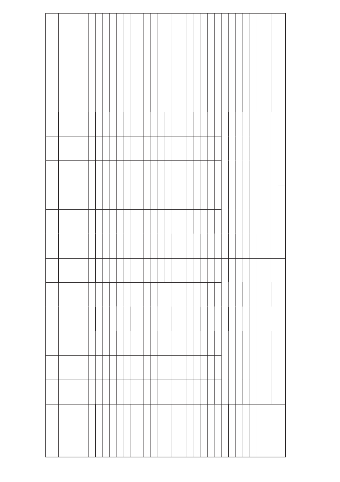
Table for difference of function
• Abbreviation
EE : East European model
NE : North European model
RU : Russian model
AUS : Australian model
HK : Hong Kong model
CN : Chinese model
JE : Tourist model
CCD-
TR V37E
AEP, UK,
EE, NE,
RU
8
510H
1/6
20×
40×(*3)
40× (*1),
240× (*3)
2.5
Mono
a
a
CCD-
TRV47E
E, AUS,
HK, CN,
JE
RMT-708
8
510H
1/6
20×
40×
200×
2.5
Mono
a
a
CCD-
TRV48E
AEP, UK,
EE, NE,
RU
RMT-708
8
510H
1/6
20×
40×
80× (*1),
360×
2.5
Mono
a
a
CD-240
CF-67
EJ-30
PD-117
MA-375
PJ-100
SE-101
VF-129
CCD-
TRV57E
E, AUS,
HK, CN,
JE, AEP,
UK, EE,
NE, RU
RMT-708
8
510H
1/4
20×
40×
80× (*1),
360×
2.5
a
Mono
a
a
a
CCD-
TRV67E
E, AUS,
HK, CN,
JE, AEP,
UK, EE,
NE, RU
RMT-708
Hi8
510H
1/4
20×
40×
80× (*1),
360×
2.5
a
Mono
a
a
a
VL-29
Model
Destination
Remote commander
8/Hi8
CCD imager
CCD imager size (inch)
Lens Optical
Digital zoom 1
Digital zoom 2
LCD panel (inch)
Back light, LCD
VTR REC
Steady shot
DIGITAL EFFECT
Photo mode
Audio system
Headphone jack
Night shot
LASER LINK
Video Light
CD board
CF board
EJ board
PD board
MA board
PJ board
SE board
VF board
VL board
CCD-
TR317E
E, AUS,
HK, CN
8
510H
1/6
20×
40×
200×
Mono
a
CCD-
TR417E
AEP, UK,
EE, NE,
RU
8
510H
1/6
20×
40×(*3)
40× (*1),
240× (*3)
Mono
a
CCD-
TR427E
AEP, UK,
EE, NE,
RU
RMT-708
8
510H
1/6
20×
40×
80× (*1),
360×
Mono
a
CD-239
CF-66
EJ-29
MA-374
PJ-99
VF-129
CCD-
TR617E
AEP, EE,
NE, RU
RMT-708
8
510H
1/4
20×
40×
80× (*2),
360×
a
Mono
a
a
CCD-
TR717E
AEP, UK,
EE, NE,
RU
RMT-708
Hi8
510H
1/4
20×
40×
80× (*1),
360×
a
Mono
a
a
SE-100
VL-28
CCD-
TR918E
AEP, UK,
EE, NE,
RU
RMT-708
Hi8
760H
1/4
20×
40×
80× (*1),
360×
a
a
a
a
Stereo
SUPER
a
a
CCD-
TRV87E
E, AUS,
HK, CN,
JE, AEP,
UK, EE,
NE, RU
RMT-708
Hi8
760H
1/4
20×
40×
80× (*1),
360×
2.5
a
a (*4)
a
a
a
Stereo
a
SUPER
a
a
Remark
RMT-708: with IC301 of MA-374/375 board.
Hi8: with S-VIDEO jack.
2.5: with PD-117 board.
a: with IC451 of SE-100/101 board.
a: with IC203 of VC-234 board.
a: with IC203 of VC-234 board.
a: with IC451 of SE-100/101 board.
SUPER: with IC203 of VC-234 board.
a: with IC751 of VC-234 board.
a: with VL-28/29 board.
*1 AEP2, UK model only
*2 AEP2 model only
*3 AEP1, EE, NE, RU model only
*4 E, AUS, HK, CN, JE model only

— 4 —
TABLE OF CONTENTS
SERVICE NOTE
1. POWER SUPPLY DURING REPAIRS ·····························7
2. TO TAKE OUT A CASSETTE WHEN NOT EJECT
(FORCE EJECT) ································································7
SELF-DIAGNOSIS FUNCTION
1. Self-diagnosis Function ······················································ 8
2. Self-diagnosis Display························································ 8
3. Service Mode Display ························································ 8
3-1. Display Method ·································································· 8
3-2. Switching of Backup No. ··················································· 8
3-3. End of Display ···································································· 8
4. Self-diagnosis Code Table ·················································· 9
1. GENERAL
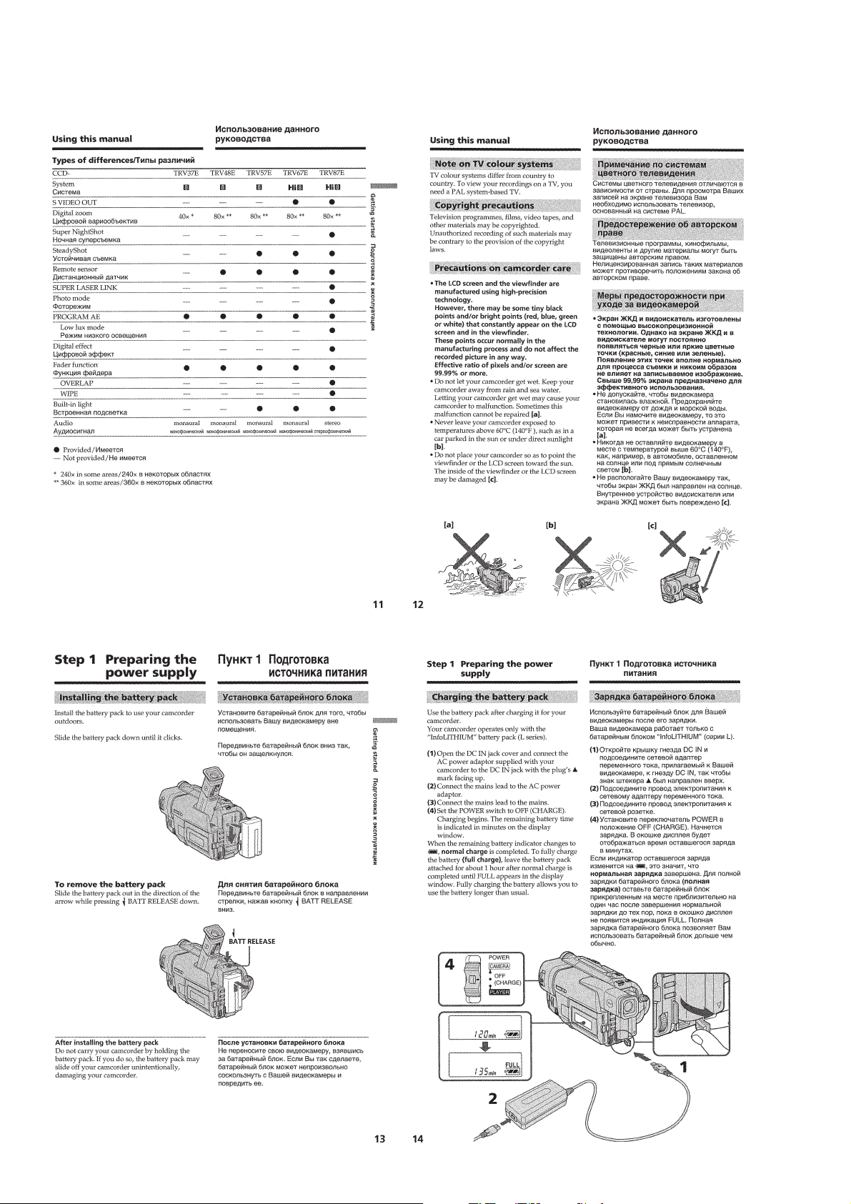
Checking supplied accessories ··················································1-1
Quick Start Guide ······································································1-1
Getting Started··········································································· 1-1
Using this manual ··································································1-1
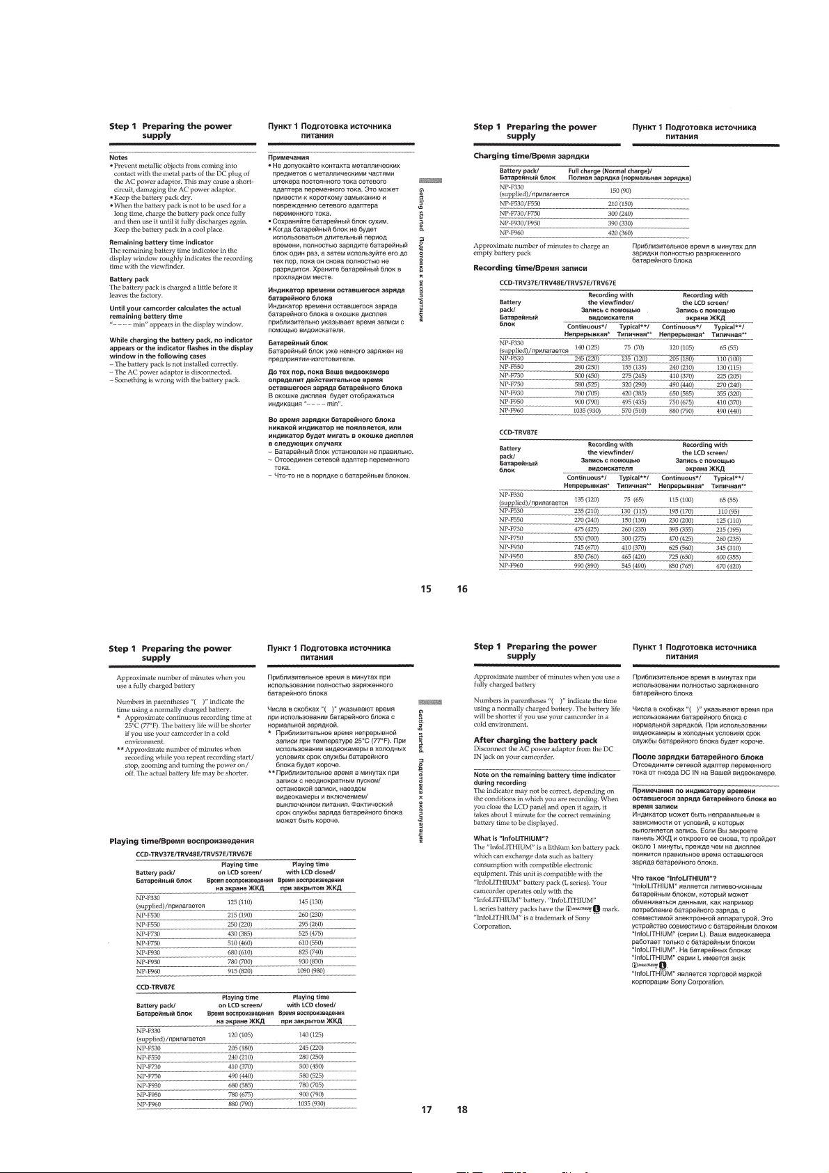
Step 1: Preparing the power supply·······································1-2
Installing the battery pack ·········································1-2
Charging the battery pack ·········································1-2
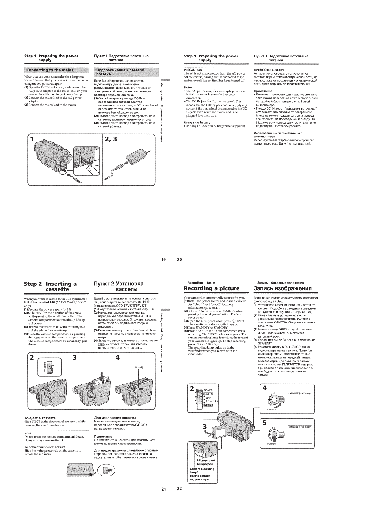
Connecting to the mains············································1-4
Step 2: Inserting a cassette ····················································1-4
Recording – Basics ····································································1-4
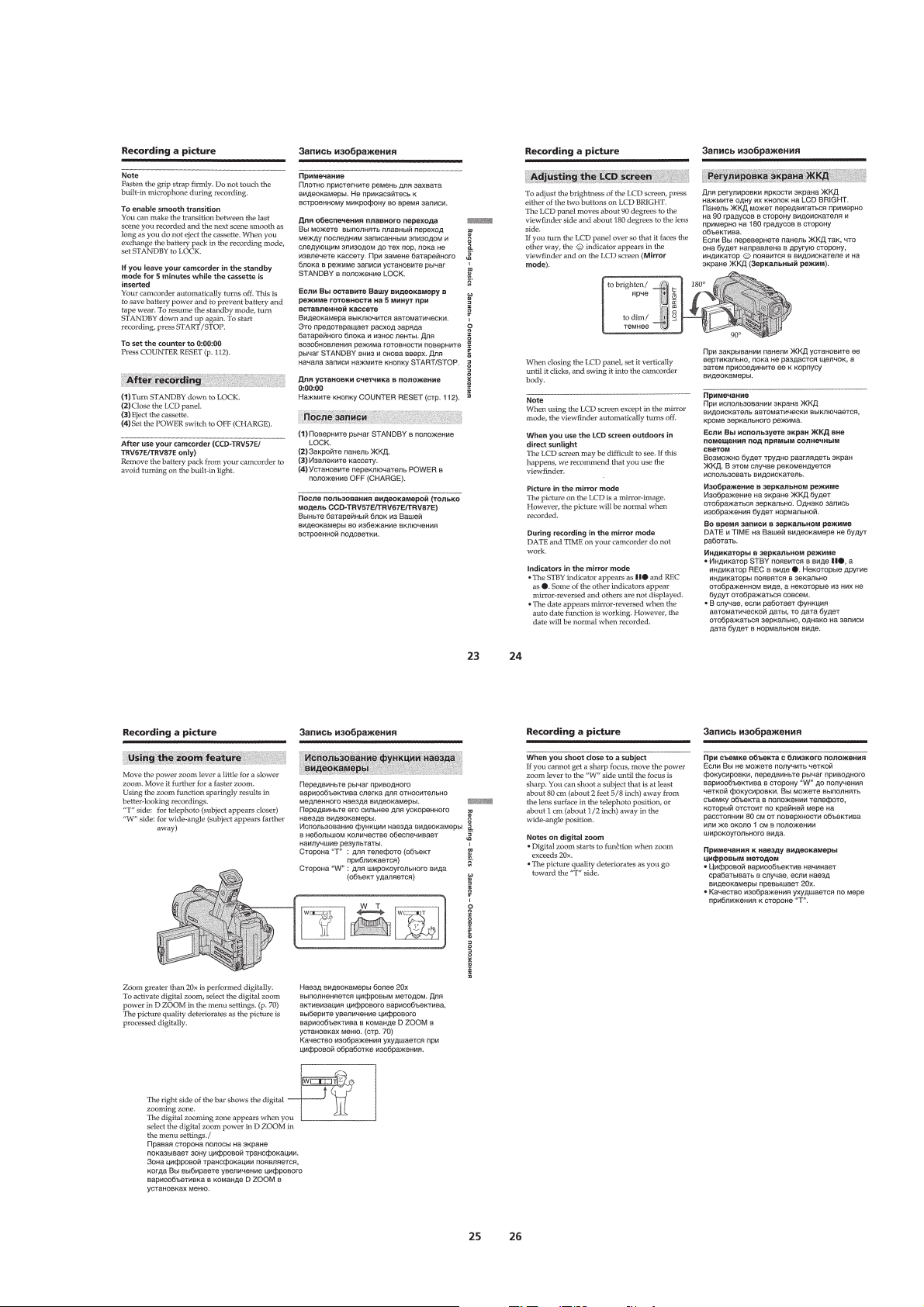
Recording a picture································································1-4
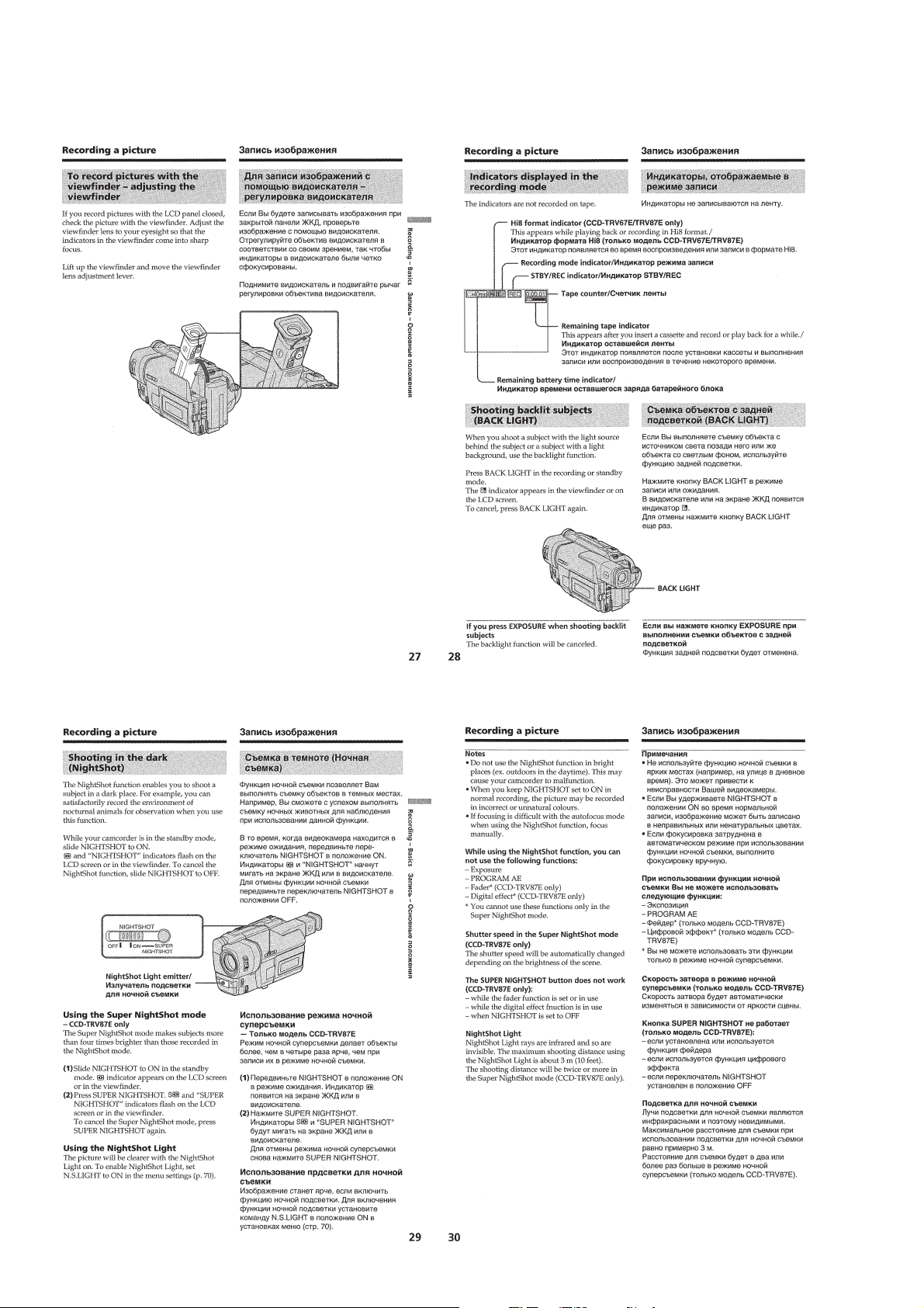
Shooting backlit subjects (BACK LIGHT)···························· 1-6
Shooting in the dark (NightShot)···········································1-6
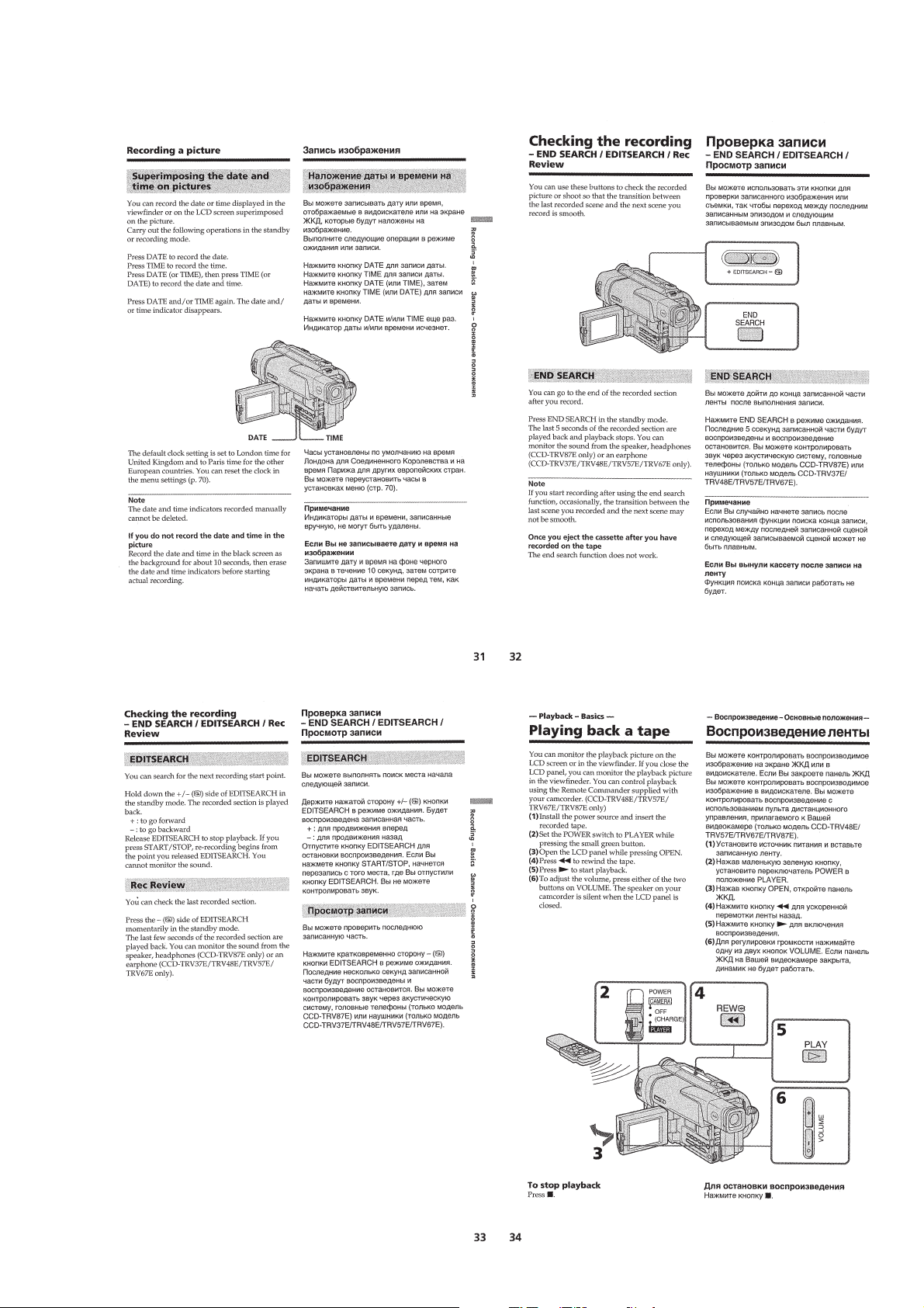
Superimposing the date and time on pictures ························1-7
Checking the recording
– END SEARCH/EDITSEARCH/Rec Review··················1-7
Playback – Basics ······································································1-7
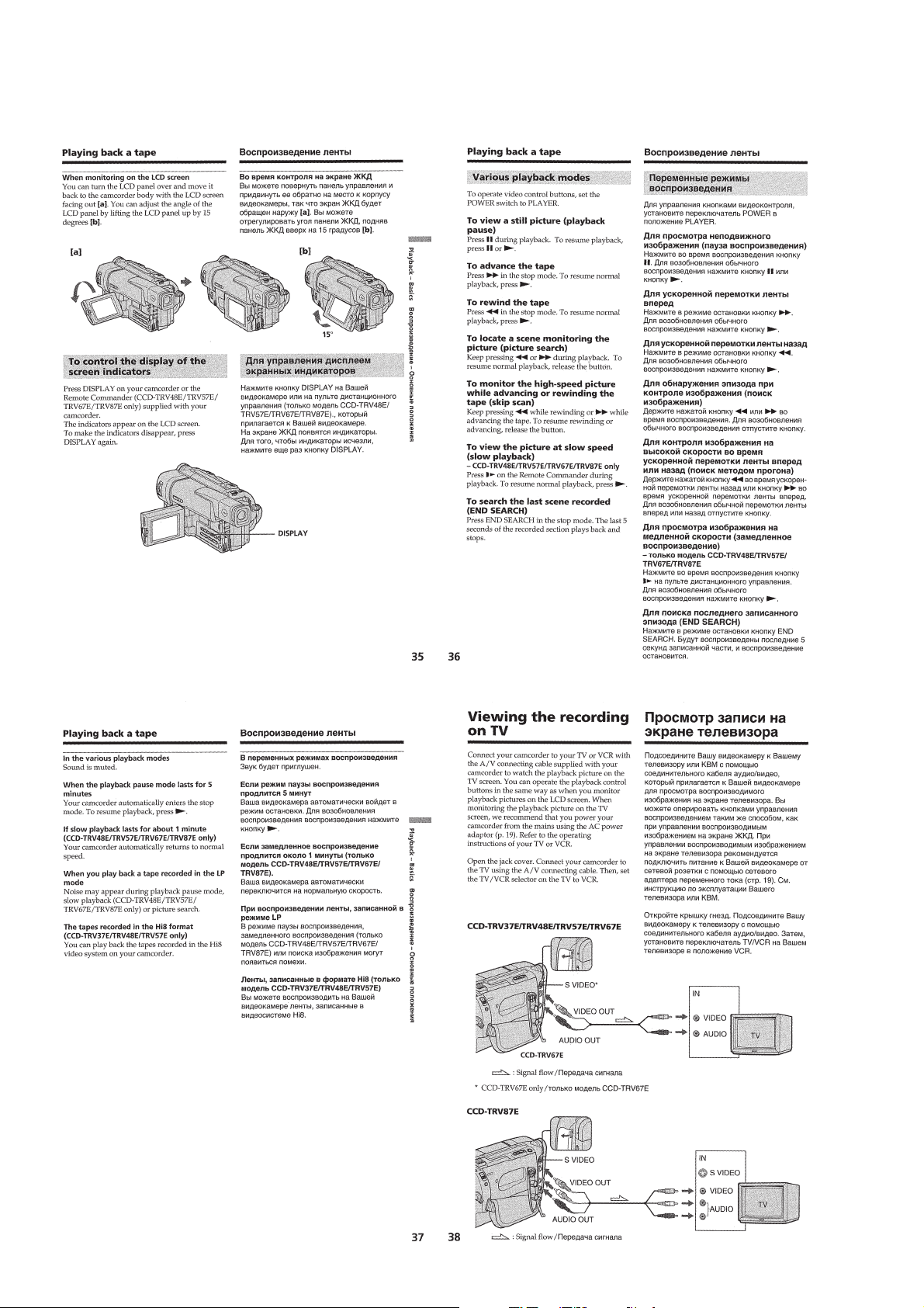
Playing back a tape ································································1-7
Viewing the recording on TV ················································1-8
Advanced Recording Operations···············································1-9
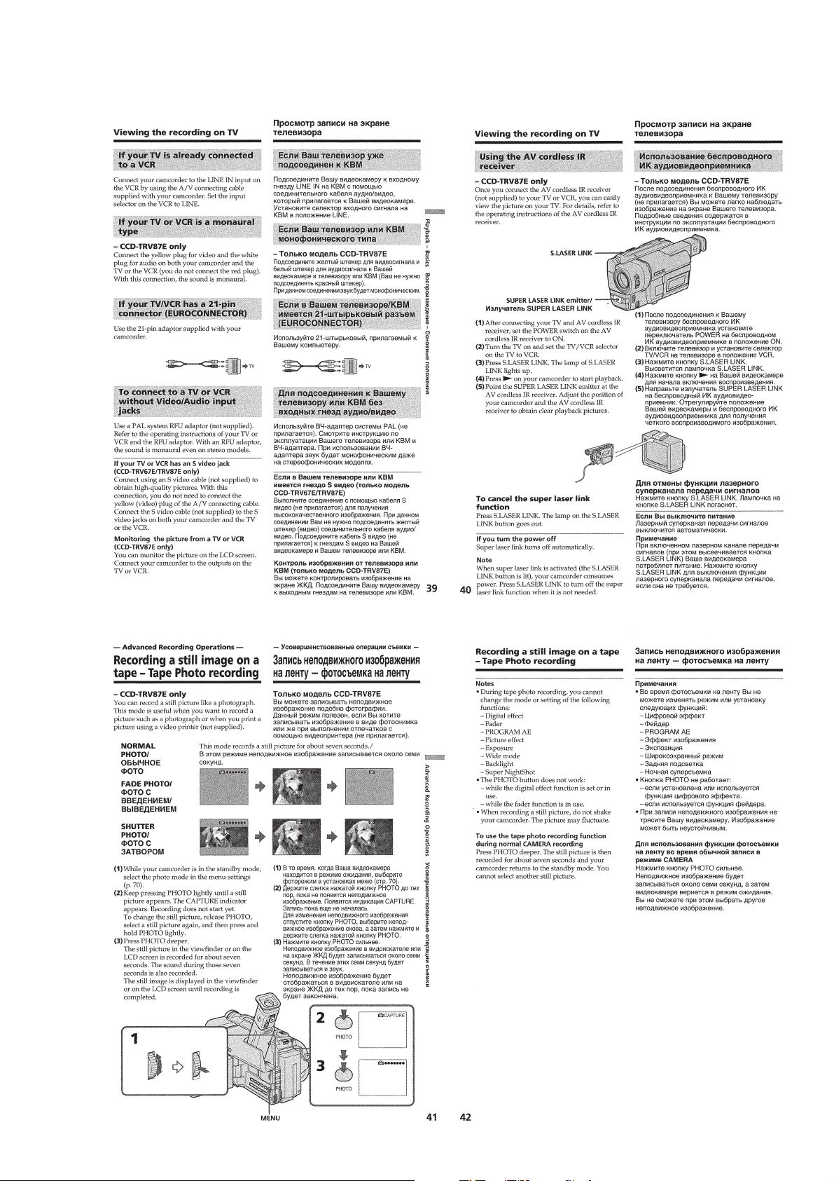
Recording a still image on a tape
– Tape Photo recording ·······················································1-9
Using the wide mode ···························································1-10
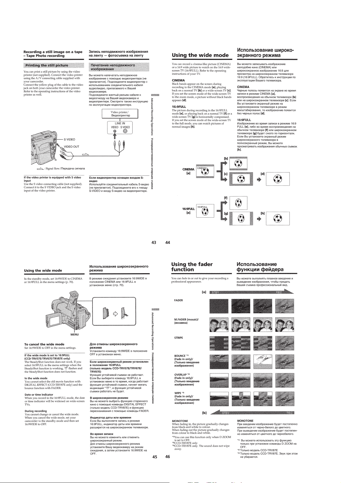
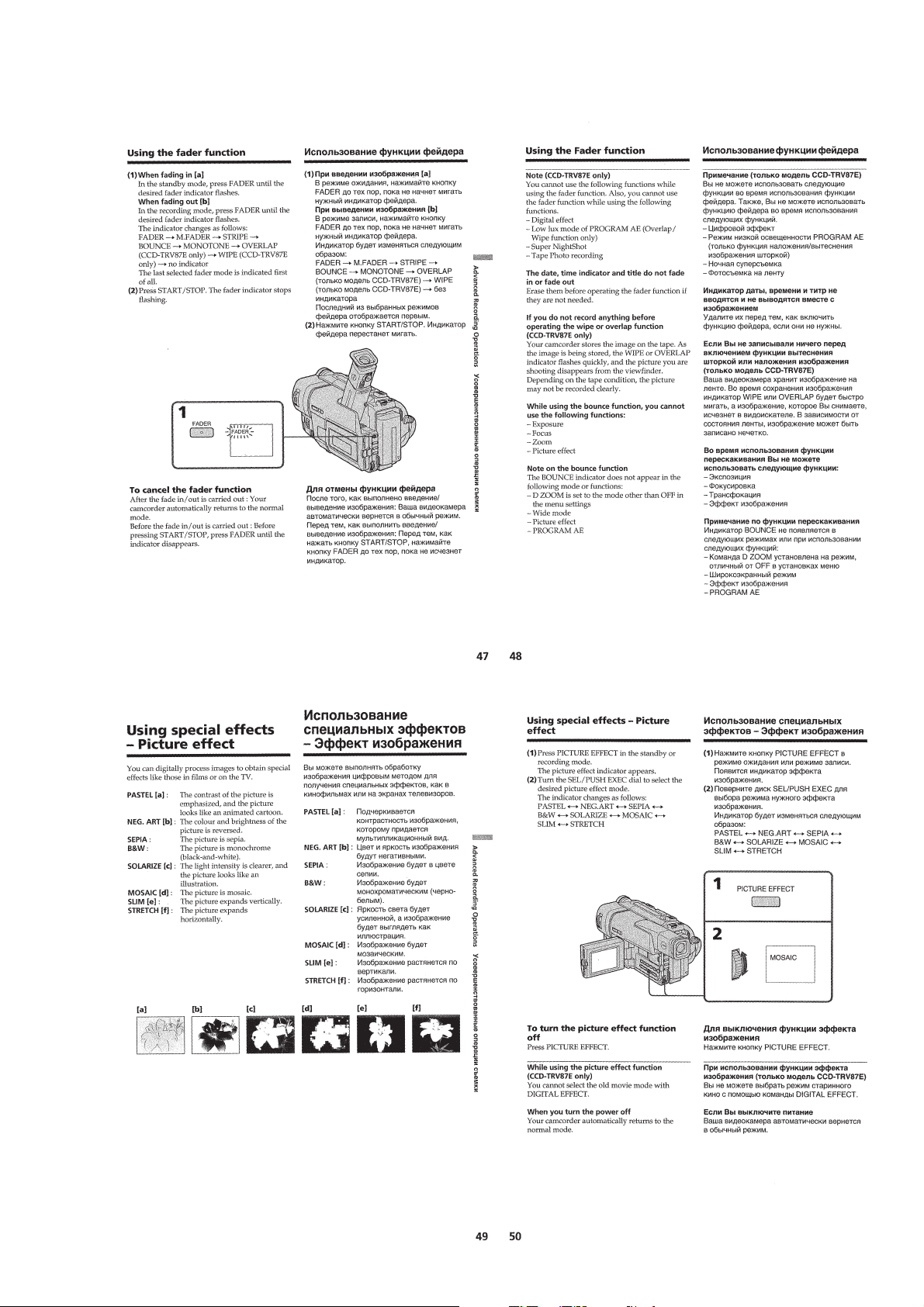
Using the fader function ······················································1-10
Using special effects – Picture effect···································1-11
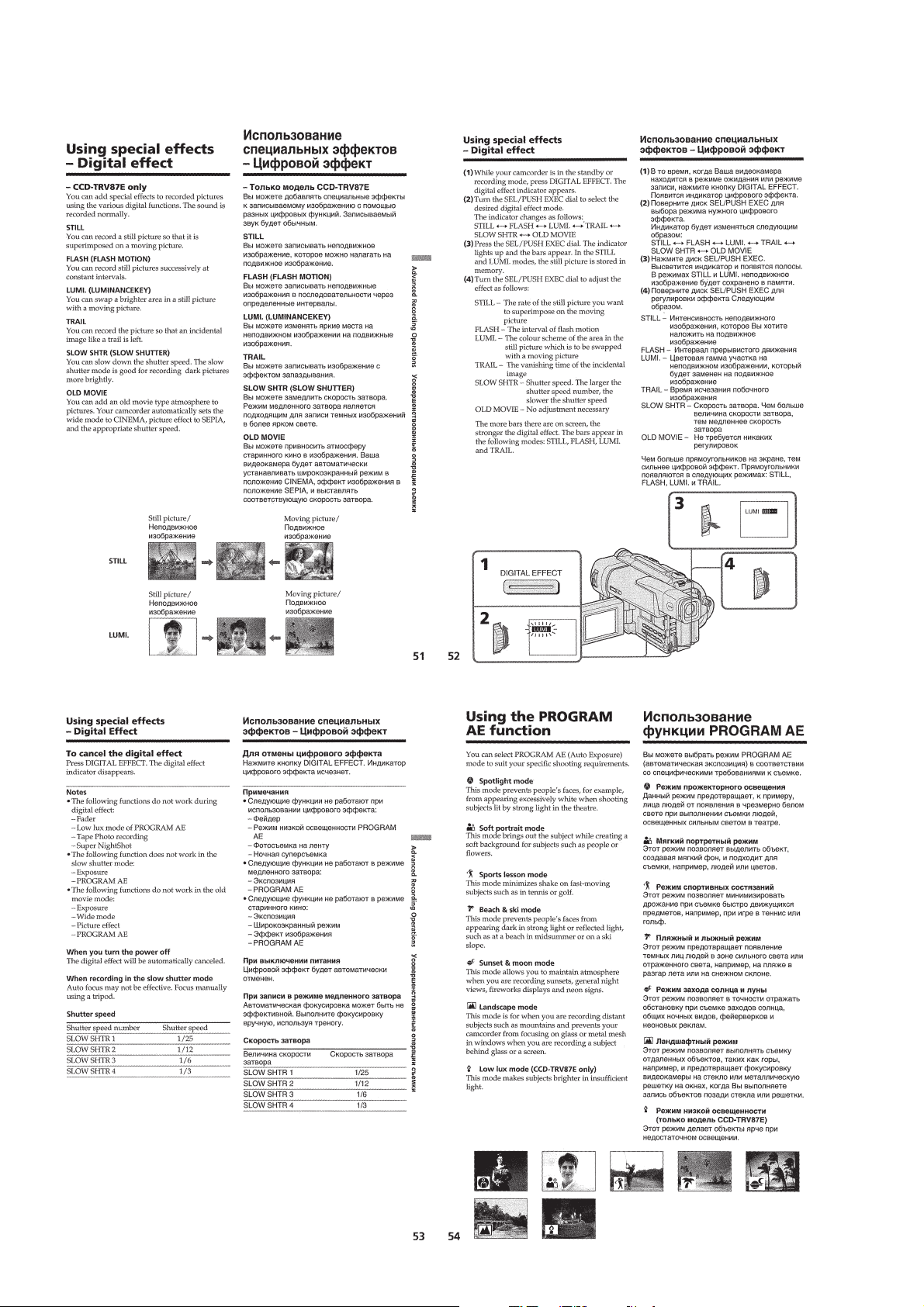
Using special effects – Digital effect···································1-12
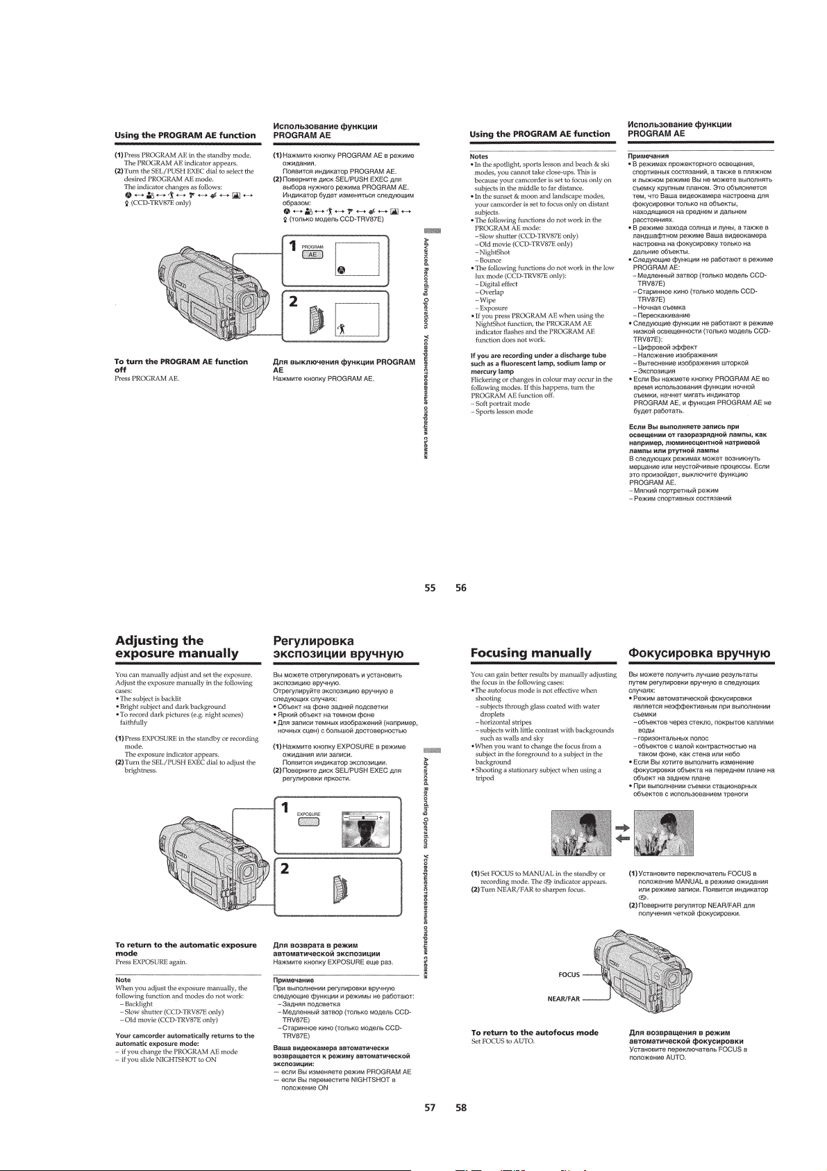
Using the PROGRAM AE function ·····································1-12
Adjusting the exposure manually ········································1-13
Focusing manually·······························································1-13
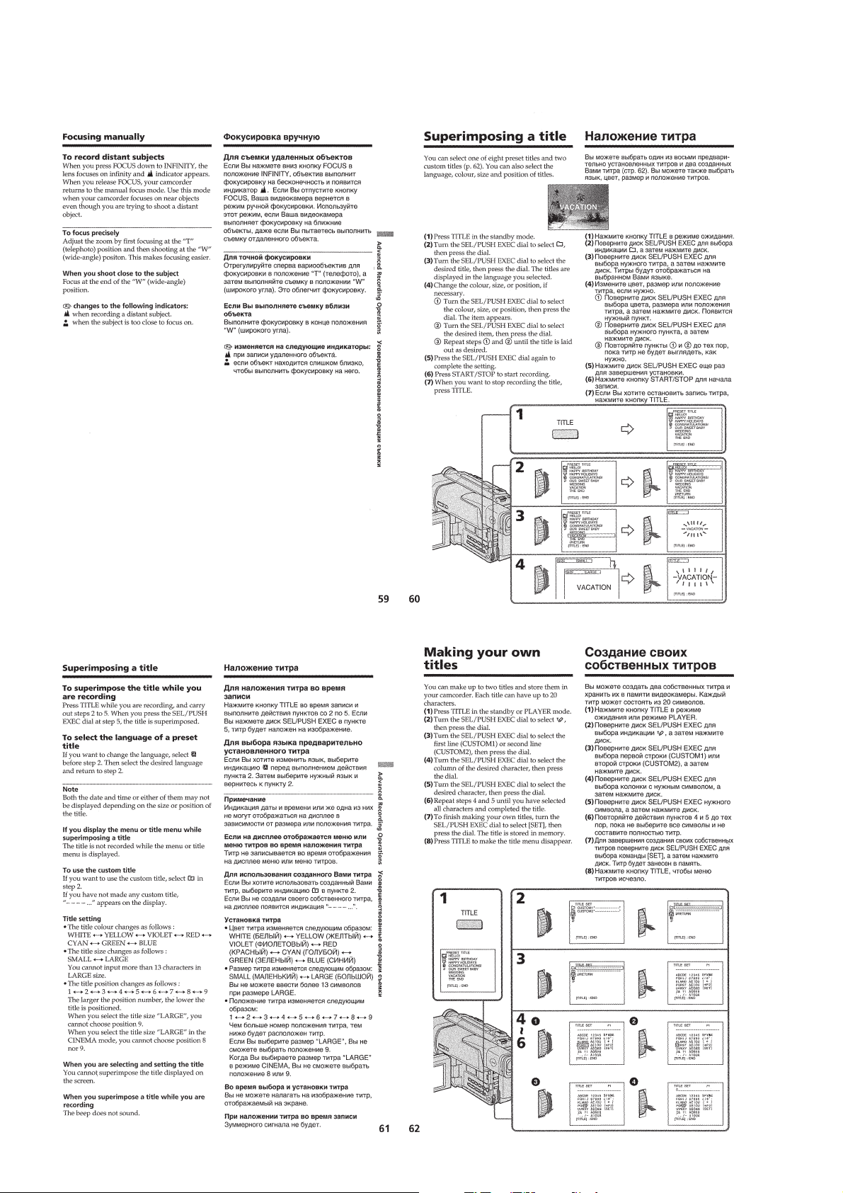
Superimposing a title ··························································· 1-14
Making your own titles ························································1-14
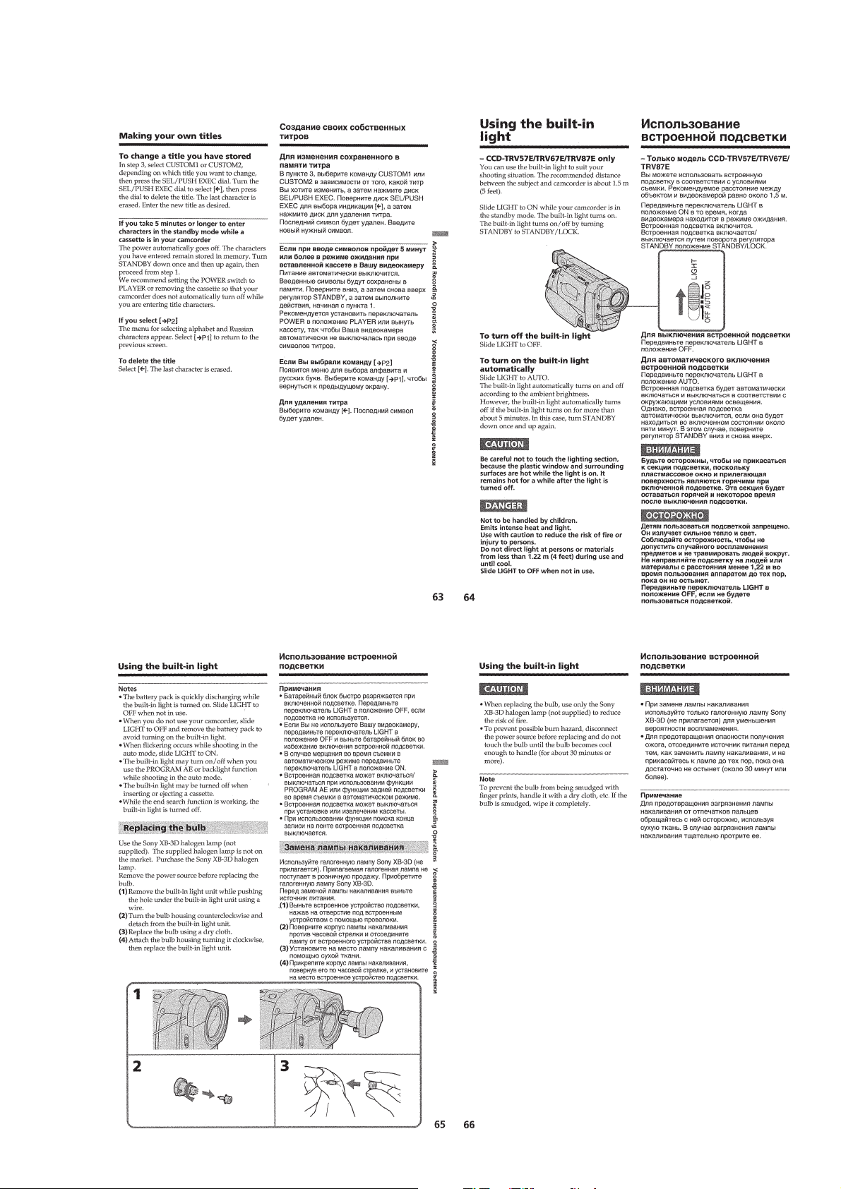
Using the built-in light························································· 1-15
Advanced Playback Operations···············································1-16
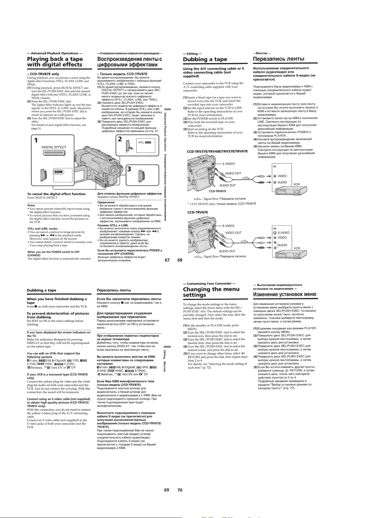
Playing back a tape with digital effects ······························· 1-16
Editing ·····················································································1-16
Dubbing a tape ·····································································1-16
Customizing Y our Camcorder ·················································1-16
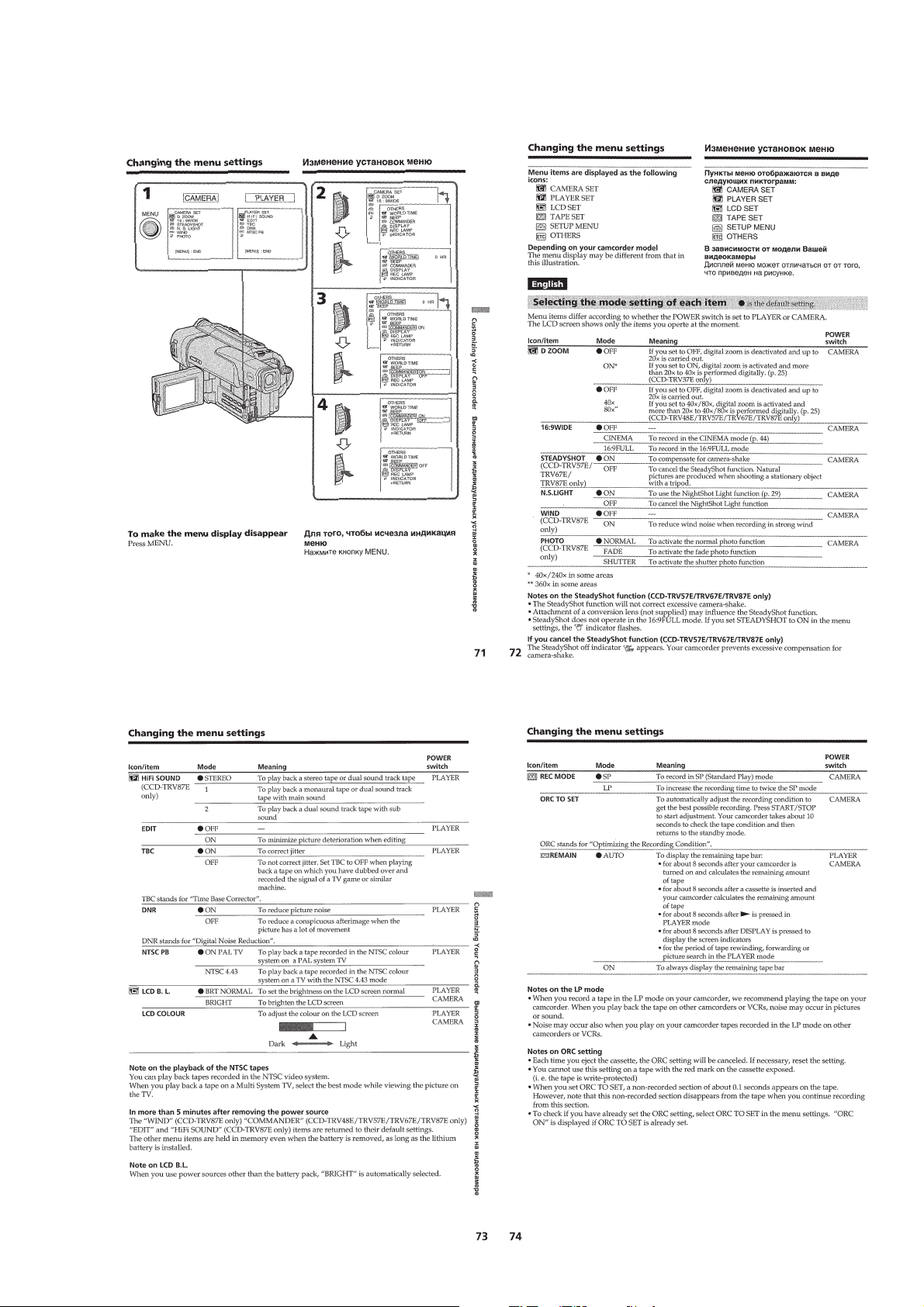
Changing the menu settings················································· 1-16
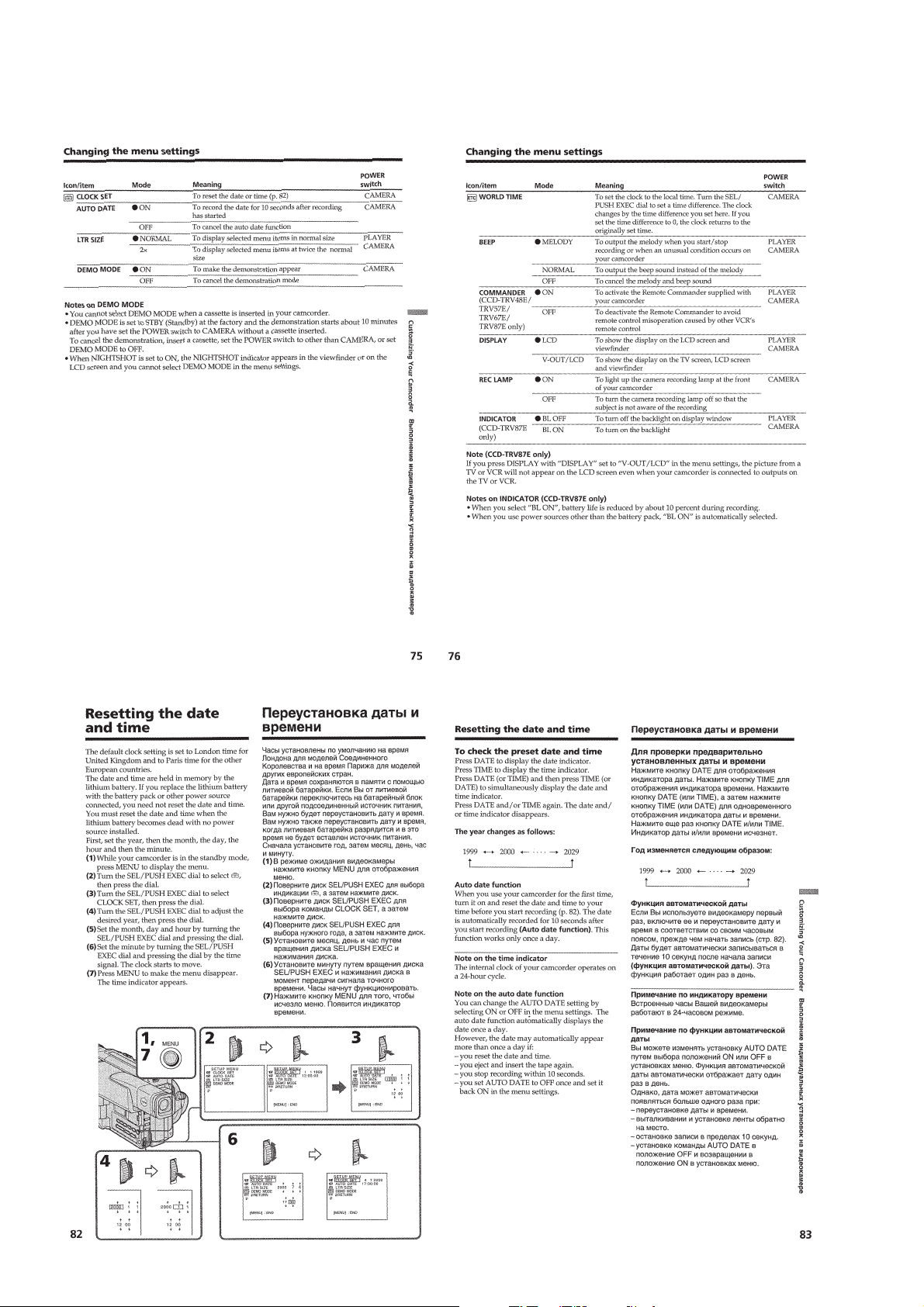
Resetting the date and time··················································1-18
Additional Information ····························································1-19
Usable cassettes and playback modes··································1-19
Changing the lithium battery in your camcorder ·················1-19
Troubleshooting ···································································1-20
Self-diagnosis display ··························································1-21
Warning indicators and messages ········································1-21
Using your camcorder abroad··············································1-21
Maintenance information and precautions···························1-21
Quick Reference ······································································1-23
Identifying the parts and controls ········································1-23
2. DISASSEMBLY
2-1. PD-117 BOARD, BACK LIGHT, LIQUID CRYSTAL
DISPLAY PANEL (TRV MODEL) ································2-2
2-2. FRONT PANEL ASSEMBLY, MA-374/375 BOARD····2-3
2-3. CABINET (R) BLOCK ASSEMBLY ·····························2-4
2-4. MECHANISM DECK-1 ················································· 2-5
2-5. EVF BLOCK ASSEMBLY ·············································2-6
2-6. VF-129 BOARD······························································2-7
2-7. LENS DEVICE, CD-239/240 BOARD ·························· 2-8
2-8. DD-134, PJ-99/100, SE-100/101 BOARDS ··················· 2-8
2-9. VC-234, EJ-29/30 BOARDS,
MECHANISM DECK-2 ·················································2-9
2-10. CF-66 BOARD, LIQUID CRYSTAL DISPLAY PANEL,
BACK LIGHT (TR MODEL) ·······································2-11
2-11. CF-67 BOARD, SPEAKER, PUSH SWITCH
(TRV MODEL) ·····························································2-12
2-12. LCD BLOCK ASSEMBLY, HINGE ASSEMBLY
(TRV MODEL) ·····························································2-12
2-13. HARNESS PROCESSING OF THE HINGE ASSEMBLY
(TRV MODEL) ·····························································2-13
2-14. CIRCUIT BOARDS LOCATION ·································2-14
2-15. FLEXIBLE BOARDS LOCATION ······························2-15
3 BLOCK DIAGRAMS
3-1. OVERALL BLOCK DIAGRAM (1/2) ···························3-1
3-2. OVERALL BLOCK DIAGRAM (2/2) ···························3-3
3-3. CAMERA/VIDEO BLOCK DIAGRAM (1/2) ···············3-5
3-4. CAMERA/VIDEO BLOCK DIAGRAM (2/2) ···············3-7
3-5. VTR/CAMERA CONTROL BLOCK DIAGRAM·········3-9
3-6. SERVO BLOCK DIAGRAM········································3-11
3-7. MODE CONTROL BLOCK DIAGRAM (1/2) ············3-13
3-8. MODE CONTROL BLOCK DIAGRAM (2/2) ············3-15
3-9. AUDIO BLOCK DIAGRAM (1/2) ·······························3-17
3-10. AUDIO BLOCK DIAGRAM (2/2) ·······························3-19
3-11. LCD BLOCK DIAGRAM (TRV MODEL) ··················3-21
3-12. EVF BLOCK DIAGRAM ·············································3-23
3-13. POWER BLOCK DIAGRAM (1/2)······························3-25
3-14. POWER BLOCK DIAGRAM (2/2)······························3-27
4 PRINTED WIRING BOARDS AND
SCHEMATIC DIAGRAMS
4-1. FRAME SCHEMATIC DIAGRAM (1/2) ·······················4-1
FRAME SCHEMATIC DIAGRAM (2/2)·······················4-3
4-2. PRINTED WIRING BOARDS AND
SCHEMATIC DIAGRAMS ············································4-5
• CD-239/240 (CCD IMAGER)
PRINTED WIRING BOARD AND
SCHEMATIC DIAGRAM ······························4-7
• VC-234 (CAMERA PROCESSOR)(1/13)
SCHEMATIC DIAGRAM ..............................4-9
• VC-234 (Y/C PROCESSOR)(2/13)
SCHEMATIC DIAGRAM ····························4-11
• VC-234 (MEMORY)(3/13)
SCHEMATIC DIAGRAM ····························4-13
• VC-234 (FOCUS/ZOOM MOTOR DRIVE)(4/13)
SCHEMATIC DIAGRAM ····························4-15
• VC-234 (REC/PB AMP)(5/13)
SCHEMATIC DIAGRAM ····························4-17
• VC-234 (LINE IN/OUT)(6/13)
SCHEMATIC DIAGRAM ····························4-19
• VC-234 (IR TRANSMITTER)(7/13)
SCHEMATIC DIAGRAM ····························4-21
• FP-249 (S/T REEL SENSOR, TAPE TOP),
FP-356 (TAPE END), FP-355 (TAPE LED)
FLEXIBLE BOARD·····································4-23
• VC-234 (EVR D/A)(8/13)
SCHEMATIC DIAGRAM ····························4-23
• VC-234 (MODE CONTROL)(9/13)
SCHEMATIC DIAGRAM ····························4-25
• VC-234 (SERVO)(10/13)
SCHEMATIC DIAGRAM ····························4-27

— 5 —
• VC-234 (HI CONTROL)(11/13)
SCHEMATIC DIAGRAM ····························4-29
• VC-234 (AUDIO)(12/13)
SCHEMATIC DIAGRAM ····························4-31
• VC-234 (DC IN)(13/13)
SCHEMATIC DIAGRAM ····························4-33
• VC-234 (CAMERA, Y/C PROCESSOR,
FOCUS/ZOOM MOTOR DRIVE, REC/PB AMP,
LINE IN/OUT, MODE CONTROL, SERVO,
HI CONTROL, AUDIO)
PRINTED WIRING BOARD ·······················4-35
• CF-66 (USER CONTROL)
PRINTED WIRING BOARD ·······················4-39
• CF-67 (USER CONTROL)
PRINTED WIRING BOARD ·······················4-43
• CF-66 (USER CONTROL)
SCHEMATIC DIAGRAM ····························4-47
• CF-67 (USER CONTROL)
SCHEMATIC DIAGRAM ····························4-49
• EJ-29/30 (LANC CONNECTOR),
SS-9700 (START/STOP SWITCH)
PRINTED WIRING BOARDS·····················4-51
• EJ-29/30 (LANC CONNECTOR)
SCHEMATIC DIAGRAM ····························4-53
• PJ-99/100 (AV IN/OUT)
PRINTED WIRING BOARD ·······················4-56
• PJ-99/100 (AV IN/OUT)
SCHEMATIC DIAGRAM ····························4-57
• SE-100/101 (STEADY SHOT)
PRINTED WIRING BOARD ·······················4-59
• SE-100/101 (STEADY SHOT)
SCHEMATIC DIAGRAM ····························4-61
• VL-28/29 (VIDEO LIGHT)
PRINTED WIRING BOARD AND
SCHEMATIC DIAGRAM ····························4-63
• MA-374/375 (MIC AMP)
PRINTED WIRING BOARD ·······················4-65
• MA-374/375 (MIC AMP)(1/2)
SCHEMATIC DIAGRAM ····························4-67
• MA-374/375 (LASER LINK)(2/2)
SCHEMATIC DIAGRAM ····························4-69
• PD-117 (RGB LCD DRIVER, TIMING GENERATOR,
CG LCD DRIVER, BACK LIGHT DRIVE)
PRINTED WIRING BOARD ·······················4-71
• FP-152 (PANEL REVERSE)
FLEXIBLE BOARD·····································4-74
• PD-117 (RGB LCD DRIVER,
TIMING GENERATOR)(1/2)
SCHEMATIC DIAGRAM ····························4-75
• PD-117 (CG LCD DRIVER,
BACK LIGHT DRIVE)(2/2)
SCHEMATIC DIAGRAM ····························4-77
• VF-129 (B/W EVF)
PRINTED WIRING BOARD ·······················4-80
• VF-129 (B/W EVF)
SCHEMATIC DIAGRAM ····························4-81
• DD-134 (DC/DC CONVERTER)
PRINTED WIRING BOARD ·······················4-83
• DD-134 (DC/DC CONVERTER)
SCHEMATIC DIAGRAM ····························4-85
4-3. WAVEFORMS ······························································4-87
4-4. MOUNTED LOCATION ··············································4-91
5 ADJUSTMENTS
1. Before starting adjustment···············································5-1
1-1. Adjusting items when replacing main parts and boards. ··· 5-2
5-1. CAMERA SECTION ADJUSTMENT ···························5-4
1-1. PREPARATIONS BEFORE ADJUSTMENT
(CAMERA SECTION) ···················································5-4
1-1-1.List of Service Tools ························································5-4
1-1-2.Preparations ·····································································5-5
1-1-3.Precaution ········································································5-8
1. Setting the Switch····························································5-8
2. Order of Adjustments ······················································5-8
3. Subjects ···········································································5-8
1-2. INITIALIZATION OF D, E, F, 7 PAGE DATA ··············5-9
1. Initializing the D, E, F, 7 Page Data ································5-9
2. Modification of D, E, F, 7 Page Data ······························5-9
3. D Page Table···································································· 5-9
4. F Page table ···································································5-11
5. E Page Table ··································································5-13
6. 7 Page Table···································································5-16
1-3. CAMERA SYSTEM ADJUSTMENTS························5-19
1. HALL Adjustment ·························································5-19
2. Flange Back Adjustment (Using Minipattern Box)·······5-20
3. Flange Back Adjustment
(Using Flange Back Adjustment Chart and Subject
More Than 500m Away)···············································5-21
3-1. Flange Back Adjustment (1)··········································5-21
3-2. Flange Back Adjustment (2)··········································5-21
4. Flange Back Check························································5-22
5. Picture Frame Setting ····················································5-22
6. Color Reproduction Adjustment····································5-23
7. Auto White Balance & LV Standard Data Input ···········5-24
8. Auto White Balance Adjustment ··································· 5-25
9. White Balance Check ····················································5-26
10. Steady Shot Check
(CCD-TR617E/TR717E/TR918E/TRV57E/TRV67E/
TR V87E)·······································································5-26
1-4. MONOCHROME ELECTRONIC VIEWFINEDER
SYSTEM ADJUSTMENT ············································5-27
1-4-1.Horizontal Slant Check ·················································5-27
1-4-2.Centering Adjustment ····················································5-27
1-4-3.Focus Adjustment ··························································5-27
1-4-4.Aberration Adjustment ··················································5-28
1-4-5.Horizontal Amplitude Adjustment (VF-129 board) ······5-28
1-4-6.Vertical Amplitude Adjustment (VF-129 board) ···········5-29
1-4-7.Brightness Adjustment (VF-129 board) ························5-29
1-4-8.Horizontal Amplitude, V ertical Amplitude,
Focus Check ··································································5-29
1-5. LCD SYSTEM ADJUSTMENT
(CCD-TRV37E/TRV47E/TRV48E/TRV57E/TRV67E/
TRV87E)········································································ 5-30
1. LCD Initial Data Input ··················································5-30
2. VCO Adjustment (PD-117 board)·································5-31
3. RGB AMP Adjustment (PD-117 board)························5-31
4. Contrast Adjustment (PD-117 board)····························5-32
5. COM AMP Adjustment (PD-117 board) ·······················5-32
6. V-COM Adjustment (PD-117 board) ····························5-33
7. White Balance Adjustment (PD-117 board)··················5-33
5-2. MECHANISM SECTION ADJUSTMENT··················5-34
2-1. OPERA TING WITHOUT CASSETTE ························5-34
2-2. TAPE PATH ADJUSTMENT ········································5-34
1. Preparations for Adjustment··········································5-34
5-3. VIDEO SECTION ADJUSTMENTS ···························5-35
3-1. PREPARATIONS BEFORE ADJUSTMENTS ············ 5-35
3-1-1.Equipment to Required·················································· 5-35
3-1-2.Precautions on Adjusting···············································5-36
3-1-3.Adjusting Connectors ····················································5-36
3-1-4.Connecting the Equipments···········································5-37
3-1-5.Alignment Tape ·····························································5-38
3-1-6.Input/Output Level and Impedance ·······························5-38
3-1-7.Recording Mode (Standard 8/Hi8) switching
(CCD-TR717E/TR918E/TRV67E/TRV87E) ················5-38

— 6 —
3-2. SYSTEM CONTROL SYSTEM ADJUSTMENT ········5-39
1. Initialization of D, E, F, 7 Page Data ·····························5-39
3-3. SERVO SYSTEM ADJUSTMENTS ····························5-39
1. CAP FG Offset Adjustment (VC-234 board) ················5-39
2. Switching Position Adjustment (VC-234 board)···········5-39
3-4. VIDEO SYSTEM ADJUSTMENTS····························· 5-40
1. 28 MHz Origin Oscillation Adjustment
(VC-234 board) ·····························································5-40
2. AFC f
0
Adjustment (VC-234 board)······························5-40
3. Filter f
0
Adjustment (VC-234 board)·····························5-41
4. Y OUT Level Adjustment (VC-234 board) ···················5-41
5. C OUT Level Adjustment (VC-234 board) ···················5-42
6. REC Y Current Adjustment (VC-234 board) ················5-43
7. REC C/AFM Current Adjustment ·································5-44
7-1. Preparations only for the PLAYER model ····················5-44
7-2. REC C Current Check (VC-234 board) ························5-44
7-3. REC AFM Current Adjustment (VC-234 board) ··········5-45
7-4. Processing after completed adjustment only for the
PLAYER model ·····························································5-45
3-5. IR TRANSMITTER ADJUSTMENTS
(CCD-TR918E/TR V87E)··············································5-46
1. IR Video Carrier Frequency Adjustment
(VC-234 board) ·····························································5-46
2. IR Video Deviation Adjustment (VC-234 board)··········5-46
3. IR Audio Deviation Adjustment (VC-234 board) ·········5-47
3-6. STEREO AUDIO SYSTEM ADJUSTMENT
(CCD-TR918E/TR V87E) ··············································5-48
1. Deviation Adjustment···················································· 5-49
1-1. Connections ···································································5-49
1-2. Preparations only for the PLAYER model ····················5-49
1-3. 1.5 MHz Deviation Adjustment (VC-234 board)·········· 5-49
1-4. 1.7 MHz Deviation Adjustment (VC-234 board)·········· 5-50
1-5. Processing after completed adjustment only for the
PLAYER model ·····························································5-50
2. BPF f
0
Adjustment (VC-234 board) ······························5-50
3-7. MONA URAL A UDIO SYSTEM ADJUSTMENT
(CCD-TR317E/TR417E/TR427E/TR617E/TR717E/
TR V37E/TR V47E/TRV48E/TRV57E/TR V67E)···········5-51
1. 1.5 MHz Deviation Adjustment (VC-234 board) ·········· 5-51
2. BPF f
0
Adjustment (VC-234 board) ······························5-51
5-4. SERVICE MODE··························································5-52
4-1. ADJUSTMENT REMOTE COMMANDER ················5-52
1. Using the Adjustment Remote Commander··················5-52
2. Precautions Upon Using the Adjustment Remote
Commander ···································································5-52
4-2. DATA PROCESS···························································5-53
4-3. SERVICE MODE··························································5-54
1. Test Mode Setting ··························································5-54
2. Emergency Memory Address ········································5-55
2-1. EMG code (Emergency code) ·······································5-55
2-2. MSW codes ···································································5-56
3. Bit V alue Discrimination ···············································5-57
4. Input/output selection check··········································5-57
5. LED, LCD (display window) check······························5-57
6. Record of Use check······················································5-58
7. Switch check (1) ····························································5-58
8. Switch check (2) ····························································5-59
9. Headphone jack check (TRV model only) ····················5-59
6. REPAIR PARTS LIST
6-1. EXPLODED VIEWS ······················································6-1
6-1-1.FRONT PANEL BLOCK ASSEMBLY AND BATTERY
PANEL BLOCK ASSEMBLY ········································6-1
6-1-2.CABINET (R) BLOCK ASSEMBLY (TRV MODEL)
(TRV37E/TRV47E/TRV48E/TRV57E/TRV67E/
TRV87E)·········································································· 6-2
6-1-3.CABINET (R) BLOCK ASSEMBLY (TR MODEL)
(TR317E/TR417E/TR427E/TR617E/TR717E/
TR918E) ·········································································· 6-3
6-1-4.CABINET (L) BLOCK ASSEMBLY ·····························6-4
6-1-5.EVF BLOCK ASSEMBLY AND LENS BLOCK
ASSEMBLY ····································································6-6
6-1-6.LCD BLOCK ASSEMBLY (TRV MODEL)
(TRV37E/TRV47E/TRV48E/TRV57E/TRV67E/
TRV87E)·········································································· 6-7
6-1-7.CASSETTE COMPARTMENT ASSEMBLY ················6-8
6-1-8.LS CHASSIS BLOCK ASSEMBLY ·······························6-9
6-1-9.MECHANISM CHASSIS ASSEMBLY ·······················6-10
6-2. ELECTRICAL PARTS LIST ········································6-11
* Parts reference sheet and color reproduction frame are
shown on page 276 and 277.
— 7 —
SERVICE NOTE
1. POWER SUPPLY DURING REPAIRS
In this unit, about 10 seconds after power is supplied (8.4V) to the
battery terminal using the service power cord (J-6082-223-A), the
power is shut off so that the unit cannot operate.
This following two methods are av ailable to prev ent this. Take note
of which to use during repairs.
Method 1.
Connect the servicing remote commander RM-95 (J-6082-053-B)
to the LANC jack, and set the remote commander switch to the
“ADJ” side.
Method 2.
Use the DC IN terminal. (Use the AC power adaptor.)
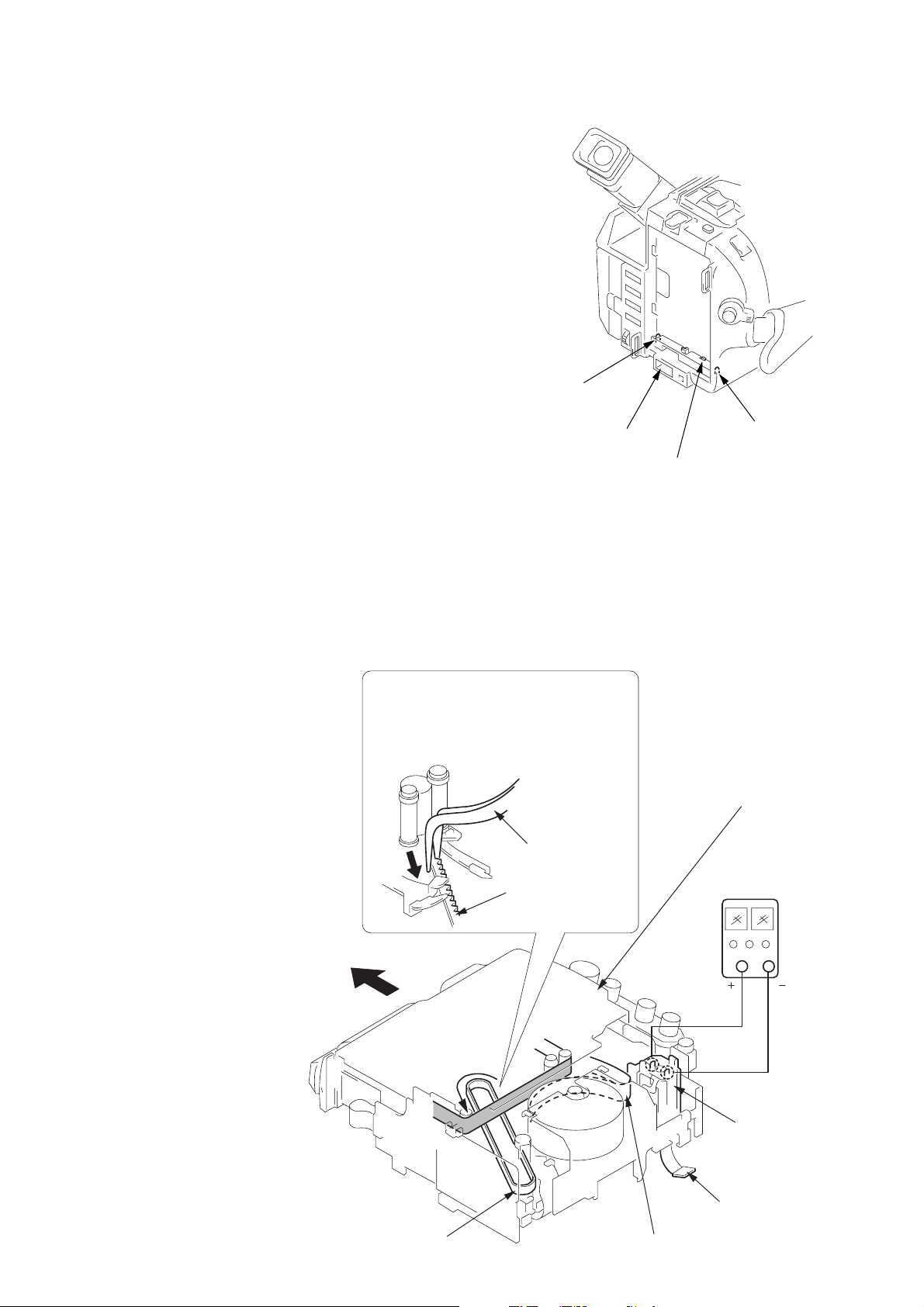
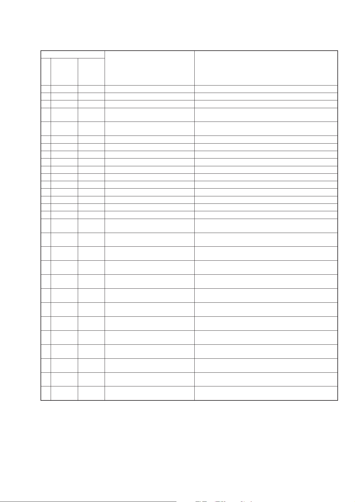
8
Pull the timing belt in the direction of
arrow
A
with a pincette while pressing
the cassette compartment (take care
not to damage) to adjust the bending
of a tape.
9
Let go your hold the cassette
compartment and rise the cassette
compartment to take out a cassette.
Pincette
Timing belt
Timing belt
Press the cassette compartment not to
rise the cassette compartment
[DC power supply]
(+5V)
Adjust the bending of a tape
Disconnect CN974
of VC-234 board.
Loading motor
DC IN terminal
Battery terminal
#
Battery terminal
3
Battery SIG terminal
2. TO TAKE OUT A CASSETTE WHEN NOT EJECT (FORCE EJECT)
1 Refer to 2-1. to remove the front panel assembly.
2 Refer to 2-1. to remove the cabinet (R) assembly.
3 Refer to 2-1. to remove the battery panel assembly.
4 Refer to 2-1. to remove the cabinet (L) assembly.
5 Refer to 2-1. to remove the cassette lid assembly.
6 Disconnect CN974 of VC-234 board.
7 Add +5V from the DC POWER SUPPLY and unload with a
pressing the cassette compartment.
— 8 —
SELF-DIAGNOSIS FUNCTION
1. Self-diagnosis Function
When problems occur while the unit is operating, the self-diagnosis
function starts working, and displays on the viewfinder or Display
window what to do. This function consists of two display; self-
diagnosis display and service mode display .
Details of the self-diagnosis functions are provided in the Instruction
manual.
Note: The “self-diagnosis display” data will be backed up by the coin-type lithium battery (CF-66/67 board BH001). When
this coin-type lithium battery is disconnected, the “self-diagnosis display” data will be lost by initialization.
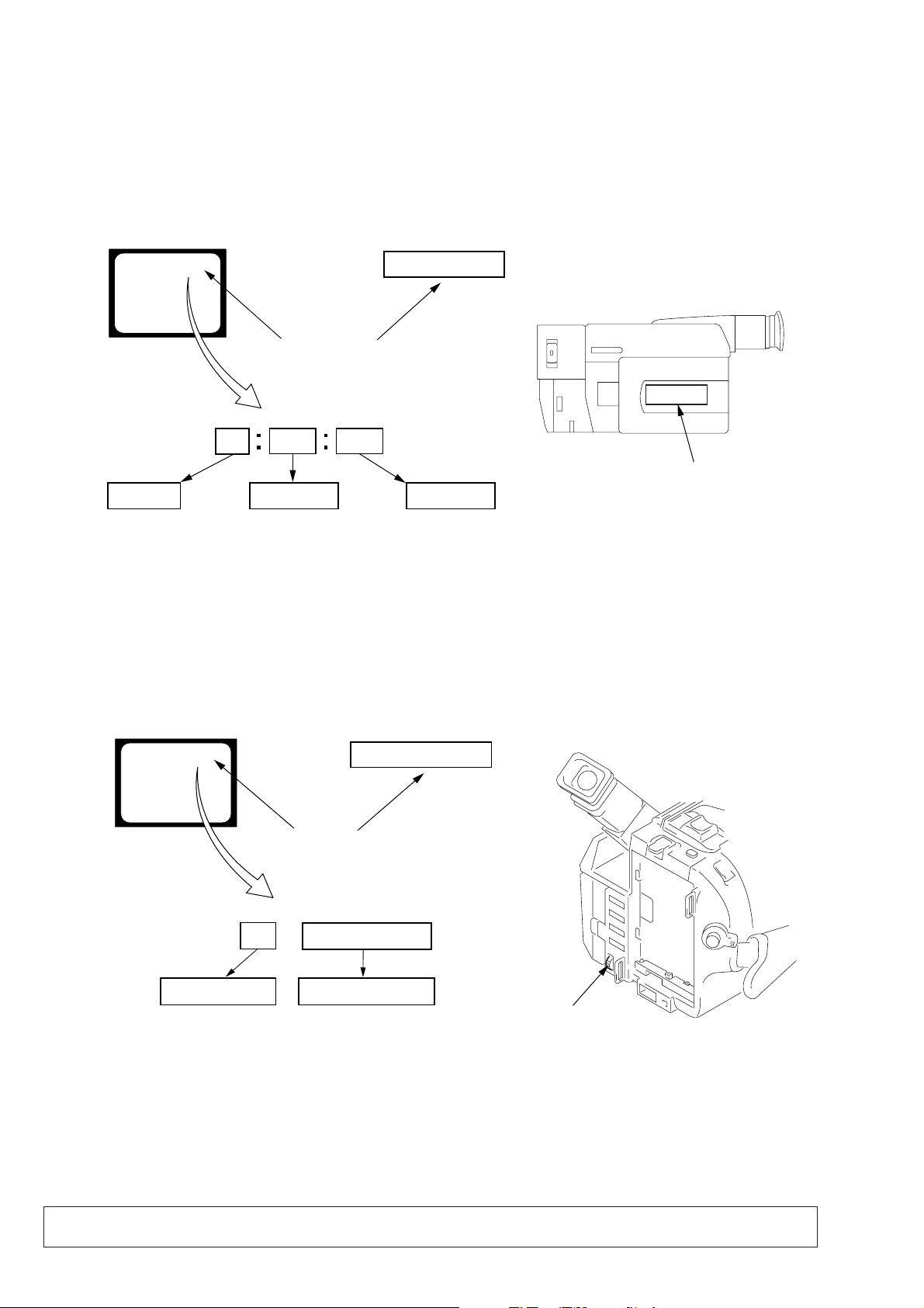
2. Self-diagnosis Display
When problems occur while the unit is operating, the counter of the
viewfinder or Display window shows a 4-digit display consisting
of an alphabet and numbers, which blinks at 3.2 Hz. This 5-character
display indicates the “repaired by:”, “block” in which the problem
occurred, and “detailed code” of the problem.
3. Service Mode Display
The service mode display shows up to six self-diagnosis codes shown in the past.
3-1. Display Method
While pressing the “STOP” key, set the switch from OFF to “VTR or PLAYER”, and continue pressing the “STOP” key for 5 seconds
continuously. The service mode will be displayed, and the counter will show the backup No. and the 5-character self-diagnosis codes.
3-2. Switching of Backup No.
By rotating the control dial, past self-diagnosis codes will be shown in order. The backup No. in the [] indicates the order in which the
problem occurred. (If the number of problems which occurred is less than 6, only the number of problems which occurred will be shown.)
[1] : Occurred first time [4] : Occurred fourth time
[2] : Occurred second time [5] : Occurred fifth time
[3] : Occurred third time [6] : Occurred the last time
3-3. End of Display
Turning OFF the power supply will end the service mode display.
Order of previous errors
Backup No.
Self-diagnosis Codes
C : 3 1 : 1 1
[3]
Lights up
Viewfinder
[3] C : 3 1 : 1 1
3 C : 3 1 : 11
Display window
1 1
3 1
C : 3 1 : 11
C
Repaired by:
Refer to page 9 and 10.
Self-diagnosis Code Table.
Indicates the appropriate
step to be taken.
E.g.
31 ....Reload the tape.
32 ....Tur n o n power again.
Block
Detailed Code
Blinks at 3.2Hz
C : Corrected by customer
H : Corrected by dealer
E : Corrected by service
engineer
Viewfinder Display window
C : 3 1 : 1 1
Display window
Control dial
— 9 —
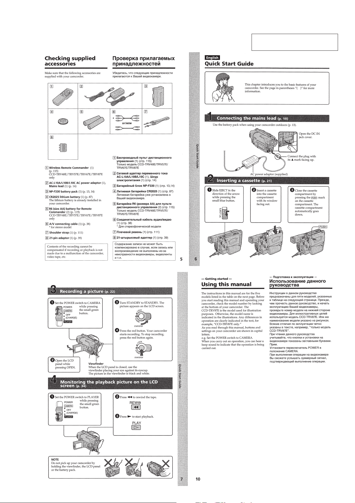
4. Self-diagnosis Code Table
C
C
C
C
C
C
C
C
C
C
C
C
C
C
C
C
C
C
C
C
C
C
C
C
C
C
C
C
C
Block
Function
04
21
22
31
31
31
31
31
31
31
31
31
31
31
31
31
32
32
32
32
32
32
32
32
32
32
32
32
32
Detailed
Code
00
00
00
10
11
20
21
22
23
30
31
40
41
42
43
44
10
11
20
21
22
23
30
31
40
41
42
43
44
Symptom/State
Non-standard battery is used.
Condensation.
Video head is dirty.
LOAD direction. Loading does not
complete within specified time
UNLOAD direction. Loading does not
complete within specified time
T reel side tape slacking when unloading
.
S reel
side tape slacking when unloading
.
T reel fault.
S reel fault.
FG fault when starting capstan.
FG fault during normal capstan operations.
FG fault when starting drum.
PG fault when starting drum.
FG fault during normal drum operations.
PG fault during normal drum operations.
Phase fault during normal drum operations.
LOAD direction loading motor time-
out.
UNLOAD direction loading motor
time-out.
T reel side tape slacking when
unloading.
S reel side tape slacking when
unloading.
T reel fault.
S reel fault.
FG fault when starting capstan.
FG fault during normal capstan
operations.
FG fault when starting drum.
PG fault when starting drum.
FG fault during normal drum
operations.
PG fault during normal drum
operations.
Phase fault during normal drum
operations.
Self-diagnosis Code
Repaired by:
Correction
Use the InfoLITHIUM battery.
Remove the cassette, and insert it again after one hour.
Clean with the optional cleaning cassette.
Load the tape again, and perform operations from the beginning.
Load the tape again, and perform operations from the beginning.
Load the tape again, and perform operations from the beginning.
Load the tape again, and perform operations from the beginning.
Load the tape again, and perform operations from the beginning.
Load the tape again, and perform operations from the beginning.
Load the tape again, and perform operations from the beginning.
Load the tape again, and perform operations from the beginning.
Load the tape again, and perform operations from the beginning.
Load the tape again, and perform operations from the beginning.
Load the tape again, and perform operations from the beginning.
Load the tape again, and perform operations from the beginning.
Load the tape again, and perform operations from the beginning.
Remove the battery or power cable, connect, and perform
operations from the beginning.
Remove the battery or power cable, connect, and perform
operations from the beginning.
Remove the battery or power cable, connect, and perform
operations from the beginning.
Remove the battery or power cable, connect, and perform
operations from the beginning.
Remove the battery or power cable, connect, and perform
operations from the beginning.
Remove the battery or power cable, connect, and perform
operations from the beginning.
Remove the battery or power cable, connect, and perform
operations from the beginning.
Remove the battery or power cable, connect, and perform
operations from the beginning.
Remove the battery or power cable, connect, and perform
operations from the beginning.
Remove the battery or power cable, connect, and perform
operations from the beginning.
Remove the battery or power cable, connect, and perform
operations from the beginning.
Remove the battery or power cable, connect, and perform
operations from the beginning.
Remove the battery or power cable, connect, and perform
operations from the beginning.

— 10 —
E
E
E
E
Block
Function
61
61
62
62
Detailed
Code
00
10
00
01
Symptom/State
Difficult to adjust focus
(Cannot initialize focus.)
Zoom operations fault
(Cannot initialize zoom lens.)
Handshake correction function does not
work well. (With pitch angular velocity
sensor output stopped.)
Handshake correction function does not
work well. (With yaw angular velocity
sensor output stopped.)
Self-diagnosis Code
Repaired by:
Correction
Inspect the lens block focus reset sensor (Pin qs of CN551 of VC-
234 board) when focusing is performed when the control dial is
rotated in the focus manual mode and the focus motor drive circuit
(IC551 of VC-234 board) when the focusing is not performed.
Note: Use the remote commander RM-95 only for the model without the
focus dial.
Inspect the lens block zoom reset sensor (Pin qf of CN551 of VC-
234 board) when zooming is performed when the zoom lens is
operated and the zoom motor drive circuit (IC551 of VC-234 board)
when zooming is not performed.
Inspect pitch angular velocity sensor (SE451 of SE-101 board)
peripheral circuits.
Inspect yaw angular velocity sensor (SE452 of SE-101 board)
peripheral circuits.
1-1
SECTION 1
GENERAL
This section is extracted from
instruction manual. (3-868-324-11)
CCD-TR317E/TR417E/TR427E/TR617E/TR717E/TR918E/
TRV37E/TR V47E/TR V48E/TR V57E/TRV67E/TR V87E
1-2
1-3
1-4
1-5
1-6
1-7
1-8
1-9
1-10
1-11
1-12
1-13
1-14
1-15
1-16
1-17
1-18
1-19
1-20
 Loading...