


SM 1619X04463 05-09:SM 1619X04463 05-09 5/29/09 3:21 PM Page 1
IMPORTANT: |
IMPORTANT : |
IMPORTANTE: |
Read Before Using |
Lire avant usage |
Leer antes de usar |
|
|
|
Operating/Safety Instructions 
 Consignes de fonctionnement/sécurité
Instrucciones de funcionamiento y seguridad
4570
|
Call Toll Free for |
|
|
|
|
|
|
|
|
|
|
|
|
|
|
|
|
|
|
|
|
|
|
|
|
|
|
|
|
|
|
|
|
|
|
|
|
|
|
|
|
|
|
|
Pour obtenir des informations |
Llame gratis para |
||||||||
Consumer Information |
et les adresses de nos centres |
obtener información |
||||||||
|
& Service Locations |
|
de service après-vente, |
para el consumidor y |
||||||
|
|
|
appelez ce numéro gratuit |
ubicaciones de servicio |
||||||
|
|
|
|
|
|
|
|
|
||
|
1-877-SKIL999 (1-877-754-5999) www.skil.com |
|
||||||||
|
|
|
|
|
|
|
|
|
|
|
For English Version |
|
Version française |
Versión en español |
|||||||
|
See page 2 |
|
Voir page 20 |
Ver la página 38 |
||||||
|
|
|
|
|
|
|
|
|
|
|
SM 1619X04463 05-09:SM 1619X04463 05-09 5/29/09 3:21 PM Page 2
General Power Tool Safety Warnings
! WARNING Read all safety warnings and instructions. Failure to follow the warnings and instructions may result in electric shock, fire and/or serious injury.
SAVE ALL WARNINGS AND INSTRUCTIONS FOR FUTURE REFERENCE
The term “power tool” in all of the warnings refers to your mains-operated (corded) power tool or battery-operated (cordless) power tool.
Work area safety
Keep work area clean and well lit. Cluttered or dark areas invite accidents.
Do not operate power tools in explosive atmospheres, such as in the presence of flammable liquids, gases or dust. Power tools create sparks which may ignite the dust or fumes.
Keep children and bystanders away while operating a power tool. Distractions can cause you to lose control.
Electrical safety
Power tool plugs must match the outlet. Never modify the plug in any way. Do not use any adapter plugs with earthed (grounded) power tools. Unmodified plugs and matching outlets will reduce risk of electric shock.
Avoid body contact with earthed or grounded surfaces such as pipes, radiators, ranges and refrigerators. There is an increased risk of electric shock if your body is earthed or grounded.
Do not expose power tools to rain or wet conditions. Water entering a power tool will increase the risk of electric shock.
Do not abuse the cord. Never use the cord for carrying, pulling or unplugging the power tool. Keep cord away from heat, oil, sharp edges or moving parts. Damaged or entangled cords increase the risk of electric shock.
When operating a power tool outdoors, use an extension cord suitable for outdoor use. Use of a cord suitable for outdoor use reduces the risk of electric shock.
If operating the power tool in damp locations is unavoidable use a Ground Fault Circuit Interrupter (GFCI) protected supply. Use of an GFCI reduce the risk of electric shock.
Personal safety
Stay alert, watch what you are doing and use common sense when operating a
power tool. Do not use a power tool while you are tired or under the influence of drugs, alcohol or medication. A moment of inattention while operating power tools may result in serious personal injury.
Use personal protective equipment. Always wear eye protection. Protective equipment such as dust mask, non-skid safety shoes, hard hat, or hearing protection used for appropriate conditions will reduce personal injuries.
Prevent unintentional starting. Ensure the switch is in the off-position before connecting to power source and / or battery pack, picking up or carrying the tool.
Carrying power tools with your finger on the switch or energizing power tools that have the switch on invites accidents.
Remove any adjusting key or wrench before turning the power tool on. A wrench or a key left attached to a rotating part of the power tool may result in personal injury.
Do not overreach. Keep proper footing and balance at all times. This enables better control of the power tool in unexpected situations.
Dress properly. Do not wear loose clothing or jewelry. Keep your hair, clothing and gloves away from moving parts. Loose clothes, jewelry or long hair can be caught in moving parts.
If devices are provided for the connection of dust extraction and collection facilities, ensure these are connected and properly used. Use of dust collection can reduce dustrelated hazards.
Power tool use and care
Do not force the power tool. Use the correct power tool for your application. The correct power tool will do the job better and safer at the rate for which it was designed.
Do not use the power tool if the switch does not turn it on and off. Any power tool that cannot be controlled with the switch is dangerous and must be repaired.
-2-

SM 1619X04463 05-09:SM 1619X04463 05-09 5/29/09 3:21 PM Page 3
Disconnect the plug from the power source and/or the battery pack from the power tool before making any adjustments, changing accessories, or storing power tools. Such preventive safety measures reduce the risk of starting the power tool accidentally.
Store idle power tools out of the reach of children and do not allow persons unfamiliar with the power tool or these instructions to operate the power tool. Power tools are dangerous in the hands of untrained users.
Maintain power tools. Check for misalignment or binding of moving parts, breakage of parts and any other condition that may affect the power tools operation. If damaged, have the power tool repaired before use.
Many accidents are caused by poorly maintained power tools.
Keep cutting tools sharp and clean. Properly maintained cutting tools with sharp cutting edges are less likely to bind and are easier to control.
Use the power tool, accessories and tool bits etc. in accordance with these instructions, taking into account the working conditions and the work to be performed. Use of the power tool for operations different from those intended could result in a hazardous situation.
Battery tool use and care
Recharge only with the charger specified by the manufacturer. A charger that is suitable for one type of battery pack may create a risk of fire when used with another battery pack.
Use power tools only with specifically designated battery packs. Use of any other battery packs may create a risk of injury and fire.
When battery pack is not in use, keep it away from other metal objects like paper clips, coins, keys, nails, screws, or other small metal objects that can make a connection from one terminal to another.
Shorting the battery terminals together may cause burns or a fire.
Under abusive conditions, liquid may be ejected from the battery, avoid contact. If contact accidentally occurs, flush with water. If liquid contacts eyes, additionally seek medical help. Liquid ejected from the battery may cause irritation or burns.
Service
Have your power tool serviced by a qualified repair person using only identical replacement parts. This will ensure that the safety of the power tool is maintained.
Safety Rules for Cordless Jigsaws
Hold power tools by insulated gripping surfaces when performing an operation where the cutting tool may contact hidden wiring. Contact with a "live" wire will make exposed metal parts of the tool "live" and shock the operator.
Use clamps or other practical way to secure and support the workpiece to a stable platform. Holding the work by hand or against your body is unstable and may lead to loss of control.
Do not drill, fasten or break into existing walls or other blind areas where electrical wiring may exist. If this situation is unavoidable, disconnect all fuses or circuit breakers feeding this worksite.
Disconnect battery pack from tool or place the switch in the locked or off
position before making any assembly, adjustments or changing accessories.
Such preventive safety measures reduce the risk of starting the tool accidentally.
Never leave the trigger locked "ON". Before inserting the battery pack, check that the trigger lock is "OFF". Accidental start-ups could cause injury.
Keep hands away from cutting area. Do not reach under the material being cut.
The proximity of the blade to your hand is hidden from your sight.
Keep hands from between the gear housing and saw blade holder. The reciprocating blade holder can pinch your fingers.
Do not use dull or damaged blades. Bent blade can break easily or cause kickback.
-3-

SM 1619X04463 05-09:SM 1619X04463 05-09 5/29/09 3:21 PM Page 4
Before starting to cut, turn tool "ON" and allow the blade to come to full speed.
Tool can chatter or vibrate if blade speed is too slow at beginning of cut and possibly kickback.
Secure material before cutting. Never hold it in your hand or across legs. Small or thin material may flex or vibrate with the blade, causing loss of control.
Make certain all adjusting screws and the blade holder are tight before making a cut. Loose adjusting screws and holders can cause the tool or blade to slip and loss of control may result.
When removing the blade from the tool avoid contact with skin and use proper protective gloves when grasping the blade or accessory. Accessories may be hot after prolonged use.
! WARNING Some dust created by power sanding, sawing,
grinding, drilling, and other construction activities contains chemicals known to cause cancer, birth defects or other reproductive harm. Some examples of these chemicals are:
•Lead from lead-based paints,
•Crystalline silica from bricks and cement and other masonry products, and
•Arsenic and chromium from chemicallytreated lumber.
Your risk from these exposures varies, depending on how often you do this type of work. To reduce your exposure to these chemicals: work in a well ventilated area, and work with approved safety equipment, such as those dust masks that are specially designed to filter out microscopic particles.
Battery/Charger
Before using battery charger, read all instructions and cautionary markings on
(1) battery charger, (2) battery pack, and (3) product using battery.
Use only the charger which accompanied your product or direct replacement as listed in the catalog or this manual. Do not substitute any other charger. Use only Skil approved chargers with your product. See Functional Description and Specifications.
Do not disassemble charger or operate the charger if it has received a sharp blow, been dropped or otherwise damaged in any way. Replace damaged cord or plugs immediately. Incorrect reassembly or damage may result in electric shock or fire.
Do not recharge battery in damp or wet environment. Do not expose charger to rain or snow. If battery case is cracked or otherwise damaged, do not insert into charger. Battery short or fire may result.
Charge only Skil approved rechargeable batteries. See Functional Description and Specifications. Other types of batteries may burst causing personal injury and damage.
Charge battery pack in temperatures above +32 degrees F (0 degrees C) and below
+113 degrees F (45 degrees C). Store tool and battery pack in locations where temperatures will not exceed 120 degrees F (49 degrees C). This is important to prevent serious damage to the battery cells.
Battery leakage may occur under extreme usage or temperature conditions. Avoid contact with skin and eyes. The battery liquid is caustic and could cause chemical burns to tissues. If liquid comes in contact with skin, wash quickly with soap and water. If the liquid contacts your eyes, flush them with water for a minimum of 10 minutes and seek medical attention.
Place charger on flat non-flammable surfaces and away from flammable materials when re-charging battery pack.
The charger and battery pack heat during charging. Carpeting and other heat insulating surfaces block proper air circulation which may cause overheating of the charger and battery pack. If smoke or melting of the case are observed unplug the charger immediately and do not use the battery pack or charger.
Use of an attachment not recommended or sold by Skil may result in a risk of fire, electric shock or injury to persons.
-4-

SM 1619X04463 05-09:SM 1619X04463 05-09 5/29/09 3:21 PM Page 5
Battery Care
! WARNING When batteries are not in tool or charger, keep them
away from metal objects. For example, to protect terminals from shorting DO NOT place batteries in a tool box or pocket with
nails, screws, keys, etc. Fire or injury may result.
DO NOT PUT BATTERIES INTO FIRE OR ExPOSE TO HIGH HEAT. They may explode.
Battery Disposal
Do not attempt to disassemble the battery or remove any com ponent projecting from the battery terminals. Fire or injury may result. Prior to
disposal, protect exposed terminals with heavy insulating tape to prevent shorting.
NICKEL-CADMIUM BATTERIES
If equipped with a nickel-cadmium battery, the battery must be collected, recycled or disposed of in an environ mentally sound manner.
“The EPA certified RBRC Battery Recycling Seal on the nickel-cadmium (Ni-Cd) battery indicates Robert Bosch Tool Corporation is voluntarily participating in an industry program to collect and recycle these batteries at the end of their useful life, when taken out of service in the United States or Canada. The
RBRC program provides a convenient alterative to placing used Ni-Cd batteries
into the trash or the munici pal
waste stream, which may be illegal in your area.
Please call 1-800-8-BATTERY for information on Ni-Cd battery recycling and disposal bans/restrictions in your area, or return your batteries to a Skil/Bosch/Dremel Service Center for recycling. Robert Bosch Tool Corporation’s involvement in this program is part of our commitment to preserving our environment and conserving our natural resources.”
LITHIUM-ION BATTERIES
If equipped with a lithium-ion battery, the battery must be collected, recycled or disposed of in an environ mentally sound manner.
“The EPA certified RBRC Battery Recycling Seal on the lithium-ion (Li-ion) battery
indicates Robert Bosch Tool


 Corporation is voluntarily
 participating in an industry program to collect and recycle these batteries
at the end of their useful life, when taken out of service in the United States or Canada.
The RBRC program provides a convenient alterative to placing used Li-ion batteries into the trash or the munici pal waste stream, which may be illegal in your area.
Please call 1-800-8-BATTERY for information on Li-ion battery recycling and disposal bans/restrictions in your area, or return your batteries to a Skil/Bosch/Dremel Service Center for recycling. Robert Bosch Tool Corporation’s involvement in this program is part of our commitment to preserving our environment and conserving our natural resources.”
-5-
SM 1619X04463 05-09:SM 1619X04463 05-09 5/29/09 3:21 PM Page 6
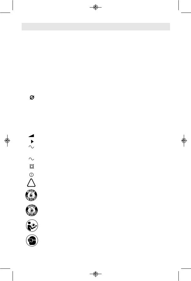
Symbols
IMPORTANT: Some of the following symbols may be used on your tool. Please study them and learn their meaning. Proper interpretation of these symbols will allow you to operate the tool better and safer.
Symbol |
Name |
Designation/Explanation |
|||||||
|
|
|
|
|
|
|
|
|
|
|
|
V |
Volts |
Voltage (potential) |
|||||
|
|
|
|
|
|
|
|
|
|
|
|
A |
Amperes |
Current |
|||||
|
|
|
|
|
|
|
|
|
|
|
Hz |
Hertz |
Frequency (cycles per second) |
||||||
|
|
|
|
|
|
|
|
|
|
|
W |
Watt |
Power |
||||||
|
|
|
|
|
|
|
|
|
|
|
kg |
Kilograms |
Weight |
||||||
|
|
|
|
|
|
|
|
|
|
min |
Minutes |
Time |
|||||||
|
|
|
|
|
|
|
|
|
|
|
|
|
s |
Seconds |
Time |
||||
|
|
|
|
|
|
|
|
|
|
|
|
|
|
|
|
|
|
Diameter |
Size of drill bits, grinding wheels, etc. |
|
|
|
|
|
|
|
|
|
|
|
n0 |
No load speed |
Rotational speed, at no load |
||||||
.../min |
Revolutions or reciprocation |
Revolutions, strokes, surface speed, |
|||||||
|
|
|
|
|
|
|
|
per minute |
orbits etc. per minute |
|
|
|
|
|
|
|
|
|
|
0 |
|
|
|
Off position |
Zero speed, zero torque... |
||||
|
|
|
|
|
|
|
|
|
|
1, 2, 3, ... |
Selector settings |
Speed, torque or position settings. |
|||||||
I, II, III, |
|
Higher number means greater speed |
|||||||
|
|
|
|
|
|
|
|
|
|
0 |
|
|
|
|
|
|
Infinitely variable selector with off |
Speed is increasing from 0 setting |
|
|
|
|
|
|
|
|
|
|
|
|
|
|
|
|
|
|
|
Arrow |
Action in the direction of arrow |
|
|
|
|
|
|
|
|
|
|
|
|
|
|
|
|
|
|
Alternating current |
Type or a characteristic of current |
|
|
|
|
|
|
|
|
|
|
|
|
|
|
|
|
|
|
Direct current |
Type or a characteristic of current |
|
|
|
|
|
|
|
|
||
|
|
|
|
|
|
|
|
|
|
|
|
|
|
|
|
|
|
Alternating or direct current |
Type or a characteristic of current |
|
|
|
|
|
|
|
|
||
|
|
|
|
|
|
|
|
|
|
|
|
|
|
|
|
|
|
Class II construction |
Designates Double Insulated |
|
|
|
|
|
|
|
|
||
|
|
|
|
|
|
|
|
|
Construction tools. |
|
|
|
|
|
|
|
|
|
|
|
|
|
|
|
|
|
|
|
|
|
|
|
|
|
|
|
|
Earthing terminal |
Grounding terminal |
|
|
|
|
|
|
|
|
|
|
|
|
|
|
|
|
|
|
Warning symbol |
Alerts user to warning messages |
|
|
|
|
|
|
|
|
|
|
|
|
|
|
|
|
|
|
|
|
|
|
|
|
|
|
|
|
Li-ion RBRC seal |
Designates Li-ion battery recycling |
|
|
|
|
|
|
|
|
|
program |
|
|
|
|
|
|
|
|
|
|
|
|
|
|
|
|
|
|
Ni-Cad RBRC seal |
Designates Ni-Cad battery recycling |
|
|
|
|
|
|
|
|
|
program |
|
|
|
|
|
|
|
|
|
|
|
|
|
|
|
|
|
|
Read manual symbol |
Alerts user to read manual |
|
|
|
|
|
|
|
|
|
|
|
|
|
|
|
|
|
|
Wear eye protection symbol |
Alerts user to wear eye protection |
|
|
|
|
|
|
|
|
|
|
-6-

SM 1619X04463 05-09:SM 1619X04463 05-09 5/29/09 3:21 PM Page 7
Symbols (continued)
IMPORTANT: Some of the following symbols may be used on your tool. Please study them and learn their meaning. Proper interpretation of these symbols will allow you to operate the tool better and safer.
This symbol designates that this tool is listed by Underwriters Laboratories.
This symbol designates that this tool is listed by Underwriters Laboratories, to United States and Canadian Standards.
This symbol designates that this tool is listed by the Canadian Standards Association.
This symbol designates that this tool is listed by the Canadian Standards
Association, to United States and Canadian Standards.
This symbol designates that this tool is listed by the Intertek Testing
Services, to United States and Canadian Standards.
This symbol designates thatthis tool compliesto NOM Mexican Standards.
-7-

SM 1619X04463 05-09:SM 1619X04463 05-09 5/29/09 3:21 PM Page 8
Functional Description and Specifications
Disconnect battery pack from tool or place the switch in the locked or ! WARNING off position before making any assembly, adjustments or changing
accessories. Such preventive safety measures reduce the risk of starting the tool accidentally.
Cordless Jigsaw
FIG. 1
TRIGGER
SWITCH BATTERY
RELEASE BUTTON
SAFETY SWITCH |
|
|
|
|
|
GEAR |
|
|
|
|
|
HOUSING |
|
|
|
|
|
BUILT IN |
|
|
|
BATTERY |
|
WORK LIGHT |
|
|
|
||
|
|
|
|
PACK |
|
PLUNGER |
|
|
|
|
|
|
|
|
VENTILATION |
|
|
|
|
|
OPENINGS |
|
|
TOOL-LESS BLADE |
|
|
|
|
|
CHANGE COVER |
|
|
|
|
|
GUIDE |
ORBIT |
FOOT |
|
|
|
CONTROL |
|
|
|
||
ROLLER |
LEVER |
|
|
|
|
|
BATTERY RELEASE |
|
|
||
|
BUTTON |
|
|
|
|
|
* BATTERY CHARGE |
|
|
||
|
CONDITION INDICATOR |
|
|
||
|
LIGHTS |
|
|
|
|
* NOT AVAILABLE ON ALL MODELS |
* BUTTON |
|
|
||
Tool |
|
Aluminum |
3/8" |
|
|
Model number |
4570 |
Mild steel |
3/16" |
|
|
Voltage rating |
18 V |
Charger (Ni-Cad) |
SC118 or SC118B |
||
No load speed |
n0 0-2100/min |
||||
Battery pack |
SB18A & SB18B |
||||
Maximum Capacities |
|
Charger (Li-ion) |
SC118B-LI |
||
Stroke length |
5/8" |
||||
Battery pack |
SB18B-LI |
||||
Blade Thickness |
Minimum 0.8mm - |
||||
Voltage rating |
120 V |
60 Hz |
|||
|
Maximum 1.5mm |
||||
|
|
|
|
||
Wood |
2" |
|
|
|
|
-8-

SM 1619X04463 05-09:SM 1619X04463 05-09 5/29/09 3:21 PM Page 9
Assembly
Attaching the Blade
! WARNING Disconnect battery pack from tool or place the
switch in the locked or off position before making any assembly, adjustments or changing accessories.
1. Insert the saw blade (teeth in cutting direction) until it latches in the plunger (Fig. 2).
FIG. 2
TOOL-LESS
BLADE CHANGE
COVER
When inserting the saw blade, the back of the blade must rest in the groove of the guide roller (Fig. 3).
2. To remove blade, lift tool-less blade change cover up with index finger and thumb and remove blade.
For use with both T or U shank jigsaw blades.
FIG. 3
BLADE
FOOT
GUIDE
ROLLER
Operating Instructions
SAFETy SWITCH
The safety switch is designed to prevent accidental starts. To operate safety switch, press the release button with your thumb on either side of handle to disengage the lock, then pull the trigger (Fig. 4). When the trigger is released the button will engage the safety switch automatically, and the trigger will no longer operate.
FIG. 4
SAFETY SWITCH
RELEASE BUTTON
VARIABLE SPEED CONTROLLED
TRIGGER SWITCH
Your tool is equipped with a variable speed trigger switch. The tool can be turned "ON" or "OFF" by squeezing or releasing the trigger. The speed can be adjusted from the minimum to maximum nameplate SPM by the pressure you apply to the trigger. Apply more pressure to increase the speed and release pressure to decrease speed (Fig. 1).
PLUNGER SPEED
The stroke rate may be adjusted as described earlier under “Variable Speed Controlled Trigger Switch”. The best results for a particular application are determined by experience, though as a general rule, slower speeds are for denser materials and faster speeds are for soft materials.
BLADE STORAGE COMPARTMENT
Your tool is equipped with a blade storage compartment (Fig. 5) on the backside of your saw. To remove, slide in direction of arrow. Be sure storage compartment is closed to prevent blades from falling out.
FIG. 5
BLADE
STORAGE
-9-

SM 1619X04463 05-09:SM 1619X04463 05-09 5/29/09 3:22 PM Page 10
BUILT IN WORK LIGHT |
FIG. 6 |
Your tool is also equipped with a light that turns on automatically when the switch is activated, for better visibility when cutting (Fig. 6).
Cutting Tips
Face the good side of the material down and secure it in a bench vise or clamp it down. Draw cutting lines or designs on the side of the material facing up towards you. Then place the front edge of the saw foot on the work and line up the blade with the line to be cut. Hold the jigsaw firmly, turn it on, and press down (to keep the saw foot flat against the work) as you slowly push the saw in the direction of the cut.
Build up cutting rate gradually, cutting close to the line (unless you want to leave stock for finish sanding). As you cut you may have to adjust or relocate the vise or clamps to keep the work stable. Do not force the saw or the blade teeth may rub and wear without cutting and the blade may break. Let the saw do most of the work. When following curves, cut slowly so the blade can cut through cross grain. This will give you an accurate cut and will prevent the blade from wandering.
ORBITAL ACTION
The orbital action lever (Fig. 7) will regulate the orbital action from "Smooth" position for normal up and down motion to maximum orbital action for faster cutting in softer materials.
FIG. 7
ORBIT
CONTROL
LEVER
To increase orbital action, turn the lever to a higher setting. To decrease orbital action turn lever to a lower setting. When minimal splintering is desired we recommend using "Smooth" position.
SMOOTH |
LOW / MED |
FAST |
MILD STEEL / SOFT METALS |
METAL PLASTIC |
SOFT WOODS |
ALL MATERIALS |
HARD WOODS |
PLYWOOD |
ATTENTION: In order to achieve orbital action, the blade must be facing STRAIGHT FORWARD and the back of the blade must rest in the groove of the guide roller, and the
foot must be all the way in the forward position. To adjust foot, lift foot adjustment lever and flip lever completely over, then push foot forward as far as possible and lower foot adjustment lever to maintain adjustment (Fig. 8).
Orbital cut control is not observable when jigsaw is free running. Jigsaw must be cutting for orbital action to occur. The speed of cut is much more apparent in thicker materials such as 2 by lumber.
FIG. 8
FOOT
BLADE
GUIDE
ROLLER
FOOT
ADJUSTMENT
LEVER
-10-
SM 1619X04463 05-09:SM 1619X04463 05-09 5/29/09 3:22 PM Page 11
CUTTING WITH A STRAIGHTEDGE
Always use a rough cut blade when possible. Clamp a straightedge on the work parallel to the line of cut and flush with the side of the saw foot. (Either first mark the line of cut and then position the straightedge parallel and at the same distance as between the blade and the side edge of the foot or first mark the side edge of the foot and then clamp the straightedge on the mark and parallel to the cut line Fig. 9)
As you cut, keep the saw foot edge flush against the straightedge and flat on the workpiece (Fig. 9).
FIG. 9 |
FOOT AGAINST |
|
STRAIGHTEDGE |
LINE
OF
CUT
CLAMPS
PLUNGE CUTTING
Plunge cutting is useful and time-saving in making rough openings in softer materials. It is not necessary to drill a hole for an inside or pocket cut. Draw lines for the opening, hold the saw firmly, tilt it forward so that the toe of the saw foot rests on the work, but with the blade well clear of the work. Start the motor, and then very gradually lower the blade. When it touches, continue pressing down on the toe of the saw foot slowly pivoting the saw like a hinge until the blade cuts through and the foot rests flat on the work. Then saw ahead on the line of cut line. We do not recommend plunge cutting with a scroll blade (Fig. 10).
To make sharp corners, cut up to the corner, then back up slightly before rounding the corner. After the opening is complete, go back to each corner and cut it from the opposite direction to square it off. Do not try to plunge cut into hard materials such as steel.
FIG. 10
TOE OF
FOOT
BEVEL OR ANGLE CUTTING
Disconnect battery pack from tool and remove the blade.
The foot can be adjusted to cut any angle from 0˚ to 45,˚ and is equipped with quick reference detent stops at 0˚, 15˚, 30˚, and 45˚.
TO ADJUST: Lift foot adjustment lever in the bottom of foot as shown, move foot slightly backward to disengage the locking tab (Fig. 11).
Position foot to desired angle, then push forward to engage locking tab and lower adjustment lever to maintain adjustment. After adjusting foot make a sample cut to check the angle, (Fig. 11).
Note: If the foot becomes loose you can use a screwdriver to tighten screw located on the
foot adjustment lever, then re-adjust the foot adjustment lever.
FIG. 11 |
FOOT |
|
ADJUSTMENT |
||
|
||
SCREW |
LEVER |
|
FOOT |
|
|
LOCKING |
|
|
TAB |
|
-11-

SM 1619X04463 05-09:SM 1619X04463 05-09 5/29/09 3:22 PM Page 12
METAL CUTTING
When cutting metal clamp material down. Be extra certain that you move the saw along slowly. Use lower speeds. Do not twist, bend, or force the blade. If the saw jumps or bounces, use a blade with finer teeth. If the blade seems clogged when cutting soft metal, use a blade with coarser teeth.
For easier cutting, lubricate the blade with a stick of cutting wax, if available, or cutting oil when cutting steel. Thin metal should be
sandwiched between two pieces of wood or tightly clamped on a single piece of wood (wood on top of the metal). Draw the cut lines or design on the top piece of wood.
When cutting aluminum extrusion or angle iron, clamp the work in a bench vise and saw close to the vise jaws.
When sawing tubing and the diameter is larger than the blade is deep, cut through the wall of the tubing and then insert the blade into the cut rotating the tube as you saw.
RIP FENCE AND CIRCLE CUTTING GUIDE
This accessory is available at an extra cost. It is used for fast and accurate straight and circle cutting (Fig. 12).
ATTACHING RIP FENCE
1.Insert bar of rip fence through the slots provided in foot, from either side of foot with the edge guide facing down (Fig. 12).
2.Thread the clamp screw from under the foot through the threaded hole in the clamp on left side of foot, and securely tighten clamp screw with a screwdriver, to clamp the rip fence bar in place.
FIG. 12
CLAMP
CLAMP |
SLOT |
|
BAR |
||
SCREW |
||
|
||
EDGE GUIDE DOWN |
|
STRAIGHT CUTTING
Once the rip fence is attached, measure from the edge of work to the line of cut, and set edge guide of rip fence to the same distance and then securely tighten clamp screw (Fig. 13).
FIG. 13
CLAMP SCREW
LINE OF CUT |
DESIRED |
|
WIDTH |
||
|
-12-

SM 1619X04463 05-09:SM 1619X04463 05-09 5/29/09 3:22 PM Page 13
CIRCLE CUTTING
1.Before attaching the rip fence, draw a circle and drive a finishing nail in the center of circle.
2.Drill or plunge cut near the circles edge, turn saw off and move the switch lock to the lock position (Fig. 14).
FIG. 14
WEDGE
EDGE |
FINISHING |
GUIDE UP |
NAIL |
3. Attach rip fence to saw with the edge guide facing UP. In order for the rip fence to cut a circle, the nail must be in alignment with the blade, as shown in (Fig. 15).
FIG. 15
BLADE MUST BE IN
ALIGNMENT WITH NAIL
NAIL
4.Measure the distance from the selected hole to the blade to be equal to the circle radius.
5.Move switch lock to the unlock position, hold the saw firmly, squeeze trigger and slowly push the saw forward. To make a hole,
cut from inside the circle; To make wheels or discs, cut from the outside.
Cutting Tip: Cut slowly so the blade will stay straight in the cut. Place small wedges in the cut as shown in Fig. 14, to keep the inner circle from spreading when near the end of the cut.
RELEASING AND INSERTING
BATTERy PACK
Release battery pack from tool by pressing the battery release button and sliding pack out of handle base (Fig. 1). To insert battery, align battery and slide battery pack into tool until it locks into position. Do not force.
IMPORTANT CHARGING NOTES (NICKEL-CADMIUM BATTERIES)
1.The battery pack accepts only about 80% of its maximum capacity with its first few charge cycles. However, after the first few charge cycles, the battery will charge to full capacity.
2.The charger was designed to fast charge the battery only when the battery temperature is between 32˚F (0˚C) and 113˚F (45˚C).
3.A substantial drop in operating time per charge may mean that the battery pack is nearing the end of its life and should be replaced.
4.If you anticipate long periods (i.e. a month or more) of non-use of your tool, it is best to run your tool down until it is fully discharged before storing your battery pack. After a long period of storage, the capacity at first recharge will be lower. Normal capacity will be restored in two or three charge/discharge cycles. Remember to unplug charger during storage period.
5.If battery does not charge properly:
a.Check for voltage at outlet by plugging in some other electrical device.
b.Check to see if outlet is connected to a light switch which turns power “off” when lights are turned off.
c.Check battery pack terminals for dirt. Clean with cotton swab if necessary.
d.If you still do not get proper charging, take or send tool, battery pack and charger to your local Skil Service Center.
Note: Use of charger’s or battery packs not sold by Skil will void the warranty
-13-

SM 1619X04463 05-09:SM 1619X04463 05-09 5/29/09 3:22 PM Page 14
BATTERy CHARGED CONDITION INDICATOR (SB18B BATTERy)
Your battery pack is equipped with charge condition indicator lights (Fig. 16). The indicator lights shows the charge condition of the battery during operation.
To check battery charge condition, depress and hold the button on the backside of the battery pack.
• • • • • When all five lights are illuminated, this indicates the batter pack is fully charged.
•• • When only three lights illuminate, this indicates the battery pack is partially charged.
•When only one light illuminates, this indicates the battery pack is slightly charged.
When no lights illuminate, this indicates the battery pack is completely discharged.
CHARGING BATTERy PACK (SC118 OR SC118B CHARGER)
Plug charger cord into your standard power outlet, then slide the battery pack into charger (Fig. 16).
The charger’s green indicator will begin to “BLINK”. This indicates that the battery is receiving a fast charge. Fast-charging will automatically stop when the battery pack is fully charged.
When the indicator light stops “BLINKING” (and becomes a steady green light) fast charging is complete.
When you begin the charging process of the battery pack, a steady green light could also mean the battery pack is too hot or too cold.
The purpose of the light is to indicate that the battery pack is fast-charging. It does not indicate the exact point of full charge. The light will stop blinking in less time if the battery pack was not completely discharged.
When the battery pack is fully charged, unplug the charger (unless you're charging another battery pack) and slip the battery pack back into the tool handle.
|
* NOT AVAILABLE ON ALL MODELS |
* BUTTON |
FIG. 16 |
|
CHARGER |
|
BATTERY |
|
PACK |
* BATTERY |
|
CHARGE |
|
CONDITION |
|
INDICATOR |
|
LIGHTS |
INDICATOR LIGHT |
-14-
SM 1619X04463 05-09:SM 1619X04463 05-09 5/29/09 3:22 PM Page 15
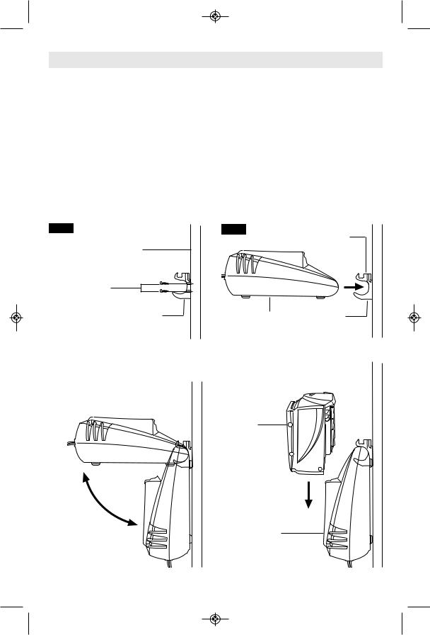
Mounting Charger
MOUNTING CHARGER TO
A VERTICAL SURFACE (Models SC118 & SC118B only)
For convenience, your charger was designed so it may be used on a flat horizontal surface, or it may be mounted onto a vertical surface. The mounting clip also features a bit storage on top of the clip.
1.Select mounting location near a electrical outlet so that the plug will reach the outlet. Check for studs or other support.
2.Using a pencil, mark two places on the surface in a vertical line about 3/4" apart.
3.Secure mounting clip to the vertical surface using two #8 round head screws (Fig. 17).
FIG. 17 |
VERTICAL |
SURFACE |
#8 ROUND HEAD |
WOOD SCREWS |
MOUNTING |
CLIP |
4.Remove battery pack from charger before mounting.
5.Insert handle of charger into the mounting clip in the horizontal position (Fig 18).
6.Gently lower the charger into the vertical position until it lays flat against the vertical surface and locks the charger into the mounting the clip (Fig. 19).
7.To remove charger when desired, raise the charger back into the horizontal position to unlock the charger, then remove charger from the mounting clip (Fig. 19).
8.To charge the battery pack, simply slide battery pack into charger (Fig. 20).
FIG. 18
BIT STORAGE
COMPARTMENT
CHARGER |
MOUNTING |
|
CLIP |
FIG. 19 |
|
FIG. 20 |
|
|
|
BATTERY
PACK
TO
UNLOCK
TO LOCK |
CHARGER |
-15-
SM 1619X04463 05-09:SM 1619X04463 05-09 5/29/09 3:22 PM Page 16
OPTIONAL ACCESSORy
Skil model SB18B-LI lithium ion battery pack is compatible with all existing Skil 18V tools that use the SB18B and SB18A Ni-Cd batteries.
! WARNING |
Only use the specified charger to charge your Li-Ion batteries. Do not charge Li- |
|
ion batteries with a Ni-Cd charger. |
|
|
|
IMPORTANT CHARGING NOTES (LITHIUM-ION BATTERIES) |
1.The charger was designed to fast charge the battery only when the battery temperature is between 32˚F (0˚C) and 113˚F (45˚C). If the battery pack is too hot or too cold, the charger will not fast charge the battery. (This may happen if the battery pack is hot from heavy use). When the battery temperature returns to between 32˚F (0˚C) and 113˚F (45˚C), the charger will automatically begin charging.
2.A substantial drop in operating time per charge may mean that the battery pack is nearing the end of its life and should be replaced.
3.Remember to unplug charger during storage period.
4.If battery does not charge properly:
a.Check for voltage at outlet by plugging in some other electrical device.
b.Check to see if outlet is connected to a light switch which turns power “off” when lights are turned off.
c.Check battery pack terminals for dirt. Clean with cotton swab and alcohol if necessary.
d.If you still do not get proper charging, take or send tool, battery pack and charger to your local Skil Service Center. See “Tools, Electric” in the Yellow Pages for names and addresses.
Note: Use of chargers or battery packs not sold by Skil will void the warranty.
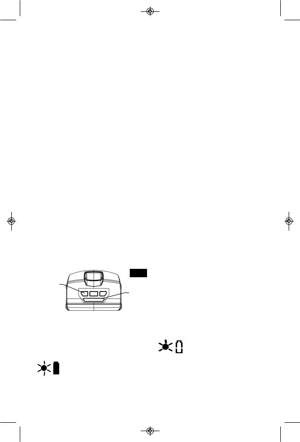
BATTERy CHARGE CONDITION INDICATOR LIGHTS (SB18B-LI BATTERy)
Your battery pack is equipped with charge condition indicator lights (Fig. 21). The indicator lights shows the charge condition of the battery during operation.
To check battery charge condition, depress and hold the button on the backside of the battery pack.
FIG. 21
* BATTERY
CHARGE
CONDITION
INDICATOR * BUTTON LIGHTS
LED |
Capacity |
|
Continuous lighting 3 x blue |
66% |
- 100% |
Continuous lighting 2 x blue |
34 - 65% |
|
Continuous lighting 1 x blue |
11 - 33% |
|
Slow flashing 1x blue |
0% |
- 10% |
|
|
|
LED |
Error Message |
Alternating |
Battery temperature is not |
left middle |
within normal operating |
right 1 |
temperature range of |
x blue |
0°C (32°F) to 45°C (113°F), |
|
or battery current is over |
|
the normal operating range. |
|
|
CHARGING BATTERy PACK (SC118B-LI CHARGER)
Plug charger cord into your standard power outlet, then insert battery pack into charger (Fig. 22).
If the green indicator light is “ON”, the charger is plugged in but the battery pack is not inserted, or the
battery pack is fully charged.
If the green indicator light is
 “BLINKING”, the battery pack is
  being fast-charged. Fastcharging will automatically stop when the
battery pack is fully charged.
-16-

SM 1619X04463 05-09:SM 1619X04463 05-09 5/29/09 3:22 PM Page 17
If the green indicator light
 is “BLINKING RAPIDLY”,
  the battery pack is too hot or cold for fast-charging. The charger will
automatically switch to fast-charging once a suitable temperature is reached, or the battery pack cannot accept a charge or the contacts of the charger or battery pack are contaminated. Clean the contacts of the charger or battery pack (e. g. by inserting and removing the battery several times) or replace the battery pack, as required.
The purpose of the light is to indicate that the battery pack is fast-charging. It does not indicate the exact point of full charge. The light will stop blinking in less time if the battery pack was not completely discharged.
When the battery pack is fully charged, unplug the charger (unless you're charging another battery pack) remove battery pack from charger and slip the battery pack back into the tool handle.
FIG. 22
BATTERY
PACK
INDICATOR LIGHT |
|
CHARGER |
|
-17-
 Loading...