


SM 2610957110 05-08 6/5/08 7:36 AM Page 1
IMPORTANT: |
IMPORTANT : |
IMPORTANTE: |
Read Before Using |
Lire avant usage |
Leer antes de usar |
Operating/Safety Instructions Consignes d’utilisation/de sécurité
Instrucciones de funcionamiento y seguridad
3375-01
|
Call Toll Free for |
Pour obtenir des informations et |
Llame gratis para |
|
Consumer Information |
les adresses de nos centres de |
obtener información |
||
|
& Service Locations |
service après-vente, |
para el consumidor y |
|
|
|
appelez ce numéro gratuit |
ubicaciones de servicio |
|
|
|
|||
|
1-877-SKIL999 (1-877-754-5999) www.skil.com |
|
||
|
|
|
|
|
|
|
|
|
|
For English Version |
Version française |
Versión en español |
||
|
See page 2 |
Voir page 18 |
Ver la página 34 |
|
|
|
|
|
|
SM 2610957110 05-08 6/5/08 7:36 AM Page 2
General Safety Rules
! WARNING “READ ALL INSTRUCTIONS” Failure to follow the safety rules listed below and other basic safety precautions may result in serious personal injury.
Work Area
KEEP CHILDREN AWAY
Do not let visitors contact tool or extension cord. All visitors should be kept safe distance from work area.
KEEP WORK AREAS CLEAN
Cluttered areas and benches invite accidents.
MAKE WORKSHOP KID-PROOF
With padlocks, master switches, or by removing starter keys.
AVOID DANGEROUS ENVIRONMENTS
Don’t use power tools in damp or wet locations. Keep work area well lit. Do not expose power tools to rain. Do not use the tool in the presence of flammable liquids or gases.
Personal Safety
KNOW YOUR POWER TOOL
Read and understand the owner’s manual and labels affixed to the tool. Learn its application and limitations as well as the specific potential hazards peculiar to this tool.
DON’T OVERREACH
Keep proper footing and balance at all times.
STAY ALERT
Watch what you are doing. Use common sense. Do not operate tool when you are tired. Do not operate while under medication or while using alcohol or other drugs.
WEAR PROPER APPAREL
Do not wear lose clothing, gloves, neckties, rings, bracelets, or other jewelry which may get caught in moving parts. Nonslip footwear is recommended. Wear protective hair covering to contain long hair.
ALWAYS USE SAFETY GLASSES
Also use face or dust mask if cutting operation is dusty, and ear plugs during extended periods of operation. Everyday eyeglasses have only impact resistant lenses, they are NOT safety glasses.
GUARD AGAINST ELECTRIC SHOCK
Prevent body contact with grounded surfaces. For example: pipes, radiators, ranges, refrigerator enclosures.
DISCONNECT TOOLS FROM POWER SOURCE
When not in use, before servicing, when changing blades, bits, cutters, etc.
KEEP GUARDS IN PLACE
In working order, and in proper adjustment and alignment.
REMOVE ADJUSTING KEYS AND WRENCHES
When not in use, before servicing, when changing blades, bits, cutters, etc.
REDUCE THE RISK OF UNINTENTIONAL STARTING
Make sure the switch is in the “OFF” position before plugging in tool.
GROUND ALL TOOLS
This tool is equipped with an approved 3-conductor cord and a 3 prong grounding type plug to fit the proper grounding type receptacle. The green conductor in the cord is the grounding wire. Never connect the green wire to a live terminal.
NEVER STAND ON TOOL OR ITS STAND
Serious injury could occur if the tool is tipped or if the cutting tool is accidentally contacted. Do not store materials on or near the tool such that it is necessary to stand on the tool or its stand to reach them.
CHECK DAMAGED PARTS
Before further use of the tool, a guard or other part that is damaged should be carefully checked to ensure that it will operate properly and perform its intended function. Check for alignment of moving parts, mounting, and any other conditions that may affect its operation. A guard or other part that is damaged should be properly replaced.
! |
WARNING |
All repairs, electrical or mechanical, |
should be attempted only by trained |
repairmen. Contact the nearest Skil Factory Service Center, Authorized Service Station or other competent repair service.
! WARNING Use only Skil replacement parts; any others may create a hazard.
! WARNING The use of any other accessories not specified in the current Skil catalog,
may create a hazard
“SAVE THESE INSTRUCTIONS”
2.
SM 2610957110 05-08 6/5/08 7:36 AM Page 3
Additional Safety Rules
Tool Use
DON’T FORCE TOOL
It will do the job better and safer at the rate for which it was designed.
USE THE RIGHT TOOL
Don’t force a small tool or attachment to do the job of a heavy duty tool. Don’t used tool for purpose not intended—for example, don’t use a circular saw for cutting tree limbs or logs.
SECURE WORK
Use clamps or a vise to hold work. It’s safer than using your hand and it frees both hands to operate the tool.
NEVER LEAVE TOOL RUNNING UNATTENDED
Turn power off. Don’t leave tool until it comes to a complete stop.
Tool Care
DO NOT ALTER OR MISUSE TOOL
These tools are precision built. Any alteration or modification not specified is misuse and may result in dangerous conditions.
AVOID GASEOUS AREAS
Do not operate electric tools in a gaseous or explosive atmosphere. Motors in these tools normally spark, and may result in a dangerous condition.
MAINTAIN TOOLS WITH CARE
Keep tools sharp and clean for best and safest performance. Follow instructions for lubricating and changing accessories. Inspect tool cords periodically and if damaged, have repaired by authorized service facility. Inspect extension cords periodically and replace if damaged. Keep handles dry, clean and free from oil and grease.
Before connecting the tool to a power ! WARNING source (receptacle, outlet, etc.), be sure
voltage supplied is the same as that specified on the nameplate of the tool. A power source with a voltage greater than that specified for the tool can result in serious injury to the user, as well as damage to the tool. If in doubt, DO NOT PLUG IN THE TOOL. Using a power source with a voltage less than the nameplate rating is harmful to the motor.
For your own safety, do not operate your ! WARNING sander until it is completely assembled
and installed according to the instructions … and until you have read and understood the following:
1.Safety Rules . . . . . . . . . . . . . . . . . . . . . . . . . . . 2–4
2.Motor Specifications . . . . . . . . . . . . . . . . . . . . . . 5
3.Getting To Know Your Belt/Disc Sander . . . . . 8
4.Assembly and Adjustments . . . . . . . . . . . . 9–13
5.Operation . . . . . . . . . . . . . . . . . . . . . . . . . . . 14–16
7.Maintaining Your Sander . . . . . . . . . . . . . . . . . 17
8. STABILITY OF THE BELT/DISC SANDER
If there is any tendency of the belt/disc sander to tilt or move during any use, bolt it to the bench top or to a piece of 3/4" exterior plywood large enough to stabilize the sander. Bolt the plywood to the underside of the base so it extends beyond the sides of the base. DO NOT USE PRESSED WOODS PANELS. They can break unexpectedly. If the workpiece is too large to easily support with one hand, provide an auxiliary support.
9. LOCATION
Use the sander in a well lit area and on a level surface, clean and smooth enough to reduce the risk of trips and falls. Use it where neither the operator nor the casual observer is forced to stand in line with a potential kickback.
10. PROTECTION: Eyes, hands, ears and body.
! |
WARNING |
TO AVOID BEING PULLED INTO |
THE SPINNING TOOL— |
DO NOT WEAR: Loose fitting gloves
Necktie
Loose clothing
Jewelry
DO: TIE BACK LONG HAIR
ROLL LONG SLEEVES ABOVE ELBOWS
a.If any part of your belt/disc sander is missing, malfunctioning, has been damaged or broken … such as the motor switch, or other operating control, a safety device or the power cord … cease operating immediately until the particular part is properly repaired or replaced.
b.Never place your fingers in a position where they could contact the sand paper or other cutting tool if the workpiece should unexpectedly shift or your hand should slip.
3.

SM 2610957110 05-08 6/5/08 7:36 AM Page 4
Additional Safety Rules
c.To prevent the workpiece from being torn from your hands, spinning on the table, shattering the tool, or being thrown, always support your work so it won’t shift or bind on the tool.
d.Never move the table support while the tool is running.
e.Before starting the operation, jog the motor switch to make sure the sanding belt or other cutting tool does not wobble or cause vibration.
f.If a workpiece overhangs the table such that it will fall or tip if not held, provide auxiliary support.
g.Use fixtures for unusual operations to adequately hold, guide and position the workpiece.
h.Turn the motor switch “OFF” and unplug from power source when not in operation.
i.Always support workpiece with the miter gage, backstop or worktable.
j.Keep fingers away from pinch points between the belt/disc and the housing.
k.Maintain 1/16” clearance maximum between table/stops and sanding belt or disc.
l.Maintain proper adjustment of sanding belt tension and alignment.
m.Avoid kickback (workpiece thrown at you) - Do not use right half of disc or work on left side of workpiece stop for belt.
n.To avoid injury from thrown work or tool contact, DO NOT perform layout, assembly, or setup work on the table while the tool is rotating.
o.Keep pulley cover closed when not making belt adjustments.
p.Do not expose to rain or use in damp locations.
q.Unplug the sander before making belt/wheel changes, adjustments or repairs.
11. DIRECTION OF FEED FOR DRUM SANDING
Feed workpiece into a sanding drum or ! WARNING other approved accessory, against the
direction of rotation.
12. THINK SAFETY
SAFETY IS A COMBINATION OF OPERATOR COMMON SENSE AND ALERTNESS AT ALL TIMES WHEN THE SANDER IS BEING USED.
Do not allow familiarity (gained from ! WARNING frequent use of your sander) to become
commonplace. Always remember that a careless fraction of a second is sufficient to inflict severe injury.
The operation of any power tool can result in foreign objects being thrown into the eyes, which can result in severe eye damage.
Always wear safety goggles that comply with ANSI Z87.1 (shown on
Package) before commencing power tool operation.
! Some dust created by power WARNING sanding, sawing, grinding, drilling, and other construction activities contains chemicals known to cause cancer, birth defects or other reproductive harm. Some examples of these
chemicals are:
•Lead from lead-based paints,
•Crystalline silica from bricks and cement and other masonry products, and
•Arsenic and chromium from chemically treated lumber.
Your risk from these exposures varies, depending on how often you do this type of work. To reduce your exposure to these chemicals: work in a well ventilated area, and work with approved safety equipment, such as those dust masks that are specially designed to filter out microscopic particles.
NOTE AND FOLLOW THE SAFETY WARNINGS AND INSTRUCTIONS THAT APPEAR ON THE PANEL ON THE SANDER:
4.

SM 2610957110 05-08 6/5/08 7:36 AM Page 5
Motor Specifications and Electrical Requirements
General Specifications
Voltage Rating . . . . . . . . . . . . . . . . . . .120 V, 60 Hz
Amperage Rating . . . . . . . . . . . . . . . . . . . . . . . .4 A
No Load Speed . . . . . . . . . . . . . . . . . .No 3,450/min
Table size . . . . . . . . . . . . . . . . . . . . . . . . . . . .9" x 6"
Motor Specifications
In the event of a malfunction or breakdown, grounding provides a path of least resistance for electric current to reduce the risk of electric shock. This tool is equipped with an electric cord having an equipment-grounding conductor and a grounding plug. The plug must be plugged into a matching outlet that is properly installed and grounded in accordance with all local codes and ordinances.
This sander is designed to use a 1700 RPM motor. It is wired for operation on 110-120 volts, 60 Hz. alternating current. Before connecting the motor cord to power source, make certain the switch is in the “OFF” position and be sure the electric current is of the same characteristics as stamped on the sander nameplate.
Connection To A Power Source
This machine must be grounded while in use to protect the operator from electric shock.
Plug power cord into a 110-120V properly grounded type outlet protected by a 15-amp dual element time delay fuse or circuit breaker.
Not all outlets are properly grounded. If you are not sure that your outlet, as pictured in Figure 1, is properly grounded; have it checked by a qualified electrician.
To avoid electric shock, do not touch the ! DANGER metal prongs on the plug when installing
or removing the plug to or from the outlet.
! DANGER |
Failure to properly ground this power tool |
|
can cause electrocution or serious |
shock, particularly when used near metal plumbing or other metal objects. If shocked, your reaction could cause your hands to hit the tool.,
! |
WARNING |
If power cord is worn, cut or damaged in |
any way, have it replaced immediately to |
avoid shock or fire hazard.
Your unit is for use on 120 volts; it has a plug that looks like the one in Figure 1.
FIG. 1
This power tool is equipped with a 3-conductor cord and grounding type plug, approved by Underwriters Laboratories and the Canadian Standards Association. The ground conductor has a green jacket and is attached to the tool housing at one end and to the ground prong in the attachment plug at the other end.
If the outlet you are planning to use for this power tool is of the two-prong type, DO NOT REMOVE OR ALTER THE GROUNDING PRONG IN ANY MANNER. Have a qualified electrician replace the TWO-prong outlet with a properly grounded THREE-prong outlet.
Improper connection of the equipment-grounding conductor can result in a risk of electric shock. The conductor with insulation having an outer surface that is green with or without yellow stripes is the equipmentconductor. If repair or replacement of the electric cord or plug is necessary, do not connect the equipmentgrounding conductor to a live terminal.
Check with a qualified electrician or service personnel if the grounding instructions are not completely understood, or if in doubt as to whether the tool is properly grounded.
Always use proper extension cord. The use of any extension cord will cause some loss of power. To keep this to a minimum and to prevent overheating and motor burn-out, use the table below to determine the minimum wire size (A.W.G.) extension cord. Use only 3-wire extension cords which have 3-prong grounding type plugs and 3-pole receptacles which accept the tool’s plug. Make sure your extension cord is in good condition.
Extension Cord Length |
Wire Size A.W.G. |
0-25 feet . . . . . . . . . . . . . . . . . . . . . . . . . . . . . . . . . . . .18
26-50 feet . . . . . . . . . . . . . . . . . . . . . . . . . . . . . . . . . .16
51-100 feet . . . . . . . . . . . . . . . . . . . . . . . . . . . . . . . . .16
“SAVE THESE INSTRUCTIONS”
5.

SM 2610957110 05-08 6/5/08 7:36 AM Page 6
Table of Contents
General Safety Rules................................................ |
2 |
Additional Safety Rules.......................................... |
3-4 |
Motor Specifications and Electrical Requirements.... |
5 |
Table of Contents...................................................... |
6 |
Unpacking and Checking Contents .......................... |
7 |
Getting to Know Your Belt/Disc Sander |
....................8 |
Assembly and Adjustments ................................ |
9 -13 |
Basic Belt/Disc Sander Operation .................... |
14 -16 |
Maintaining Your Belt/Disc Sander ........................ |
17 |
Troubleshooting ...................................................... |
17 |
6.

SM 2610957110 05-08 6/5/08 7:36 AM Page 7
Unpacking and Checking Contents
To reduce the risk of injury, never ! WARNING connect plug to power source outlet
until all assembly steps are complete and until you have read and understood the entire owner’s manual.
Model 3375 Belt/Disc Sander is shipped complete in one box.
Unpacking and Checking Contents. Separate all parts from packing materials and check each one with the “Table of Loose Parts” to make sure all items are accounted for before discarding any packing material.
If any parts are missing, do not at-
! WARNING tempt to assemble the sander, plug A in power cord or turn the switch on until the
missing parts are obtained and are installed correctly.
Table of Loose Parts
ITEM |
DESCRIPTION |
QTY. |
B |
|
|
|
|
||
A |
Belt/Disc Sander |
1 |
C |
|
B |
Work table |
1 |
|
|
C |
Table support |
1 |
|
|
D |
Mitre gauge |
1 |
E |
|
E |
Sanding disc |
1 |
||
|
||||
F |
Disc guard |
1 |
D |
|
G |
Work support |
1 |
||
|
||||
H |
Table lock knob |
1 |
|
|
I |
Pan head screw M4.2 |
2 |
|
|
J |
Hex head screw (M6 x 14) |
1 |
|
|
K |
Nut (M6) |
3 |
F |
|
L |
Washer (6.5 x 17.8 x 1.6) |
5 |
||
M |
Spring lock washer |
4 |
|
|
N |
Tooth lock washer |
1 |
G |
|
O |
Allen Key 6mm |
1 |
||
|
H
I J K
N
L M
O
7.

SM 2610957110 05-08 |
6/5/08 |
7:36 AM |
Page 8 |
|
|
|
|
Getting To Know Your Belt/Disc Sander |
|||||
|
|
|
10 |
|
11 |
|
|
|
|
|
|
12 |
|
|
|
|
|
|
|
|
|
|
9 |
|
|
|
|
|
|
8 |
|
|
|
|
|
5 |
|
|
|
|
|
|
|
4 |
|
|
|
|
|
|
|
7 |
|
|
3 |
|
|
|
|
|
|
|
|
|
|
1 |
|
|
2 |
|
14 |
|
|
|
|
|
|
|
|
15 |
|
1. |
On/off switch |
|
|
|
|
2. Base |
||
|
|
|
|
|
3. |
Mounting holes (x2) |
|
|
|
|
|
4. |
Work table |
|
|
|
|
|
5. Miter Guage |
|
13 |
|
|
|
|
6. |
Table lock knob |
|
|
|
|
7. |
Disc guard |
|
|
|
|
|
|
||
|
|
|
|
|
8. |
Sanding disc |
|
|
|
|
|
9. |
Sanding plate |
|
|
|
|
|
10. Work support |
|
|
|
|
|
|
11. Sanding belt |
|
|
|
|
|
|
12. Belt bed |
|
|
|
|
|
6 |
13. Belt tracking knob |
|
|
|
|
|
14. Belt tension lever |
||
|
|
|
|
|
||
|
|
|
|
|
15. Belt bed locking screw |
|
|
|
|
8. |
|
|
|

SM 2610957110 05-08 6/5/08 7:36 AM Page 9
Assembly and adjustments
To reduce the risk of injury, never ! WARNING connect plug to power source outlet
until all assembly steps are completed.
Installing sanding disc and guard (Fig. 2 & 3)
1.Remove the backing from the sanding disc (1). Align perimeter of disc with sanding plate (2) and press disc firmly into position all the way around, as shown in figure 2.
2.Locate disc guard (3) and two M4.2 pan head screws (4).
3.Position disc guard against lower 1/3 of disc aligning holes.
4.Using a Phillips screwdriver, fasten the pan head screws securely, applying light pressure to thread the holes, as shown in figure 3.
5.Adjust the top disc cover (5) for a 1/16” gap. Loosen the two screws, adjust as required, and retighten.
Installing work support (Fig. 4)
1.Using a wrench, secure work support (5) to side of belt & disc sander using M6 hex screw (6), spring lock washer (7) and washer (8), (Figure 4).
2.Hold work support in position and fasten.
To avoid trapping the work or ! WARNING fingers between the work support
and sanding surface, the support edge should be a maximum of 1-2 mm from sanding surface.
3.Loosen the hex screw of work support, adjust as required, and retighten.
FIG. 2
|
1 |
2 |
|
|
|
FIG. 3 |
|
5 |
|
|
|
|
3 |
|
|
4 |
|
FIG. 4 |
5 |
7 |
6 |
8 |
9.

SM 2610957110 05-08 6/5/08 7:36 AM Page 10
Assembly and adjustments
Installing table assembly (Fig. 5 & 6)
1.Position table support (1) against table (2) and align the holes.
2.Using three M6 hex nuts (3), three spring lock washers (4), and three flat washers (5), fasten the table support to the work table (Figure 5).
3.Position the table support in the corresponding holes on the side of the base, as shown in figure 6. Ensure that the 9.5 mm diameter index pin aligns with the upper hole.
4.Place a 6.5 mm washer (6) and a tooth lock washer
(7) on the end of the table lock knob (8) and insert through the table support slot and into the threaded hole of base (Figure 6).
To avoid trapping the work or ! WARNING fingers between the table and
sanding surface, the table edge should be a maximum of 1-2 mm from sanding surface.
5.Loosen the three hex head nuts at bottom of table support and adjust table as required. Adjust table as necessary and retighten.
FIG. 5 |
3 |
|
4 |
|
5 |
|
2 |
|
1 |
FIG. 6 |
7 |
6 |
8 |
10.
SM 2610957110 05-08 6/5/08 7:36 AM Page 11
Assembly and adjustments
Auxiliary mounting for vertical sanding (Fig. 7 & 8)
1.Remove work support lock and bolt, and remove work support.
2.Remove table assembly by removing table lock knob and washer.
3.Loosen the belt bed locking screw (1) and raise the belt sander bed (2) to the vertical position, figure 7.
4.Retighten the locking screw (1).
5.Attach work table assembly (3) to auxiliary holes in belt bed, figure 8. Make sure index pin is in the upper hole when sanding table is in vertical position.
!WARNING To avoid trapping the work or fingers between the table and
sanding surface, the table edge should be a maximum of 1-2 mm from sanding surface.
FIG. 7 |
2 |
1 |
FIG. 8 |
3 |
11.
SM 2610957110 05-08 6/5/08 7:36 AM Page 12
Assembly and adjustments
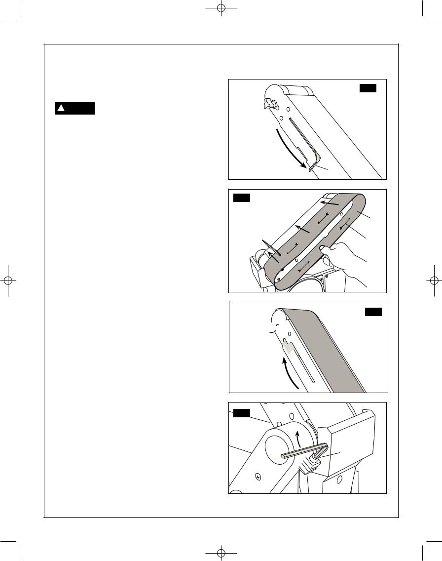
Installing the sanding belt – tensioning and tracking (Fig. 9-12)
To avoid injury from accidental start, ! WARNING turn switch ‘OFF’, remove key and
remove plug from power source outlet, before removing or installing belt.
On the smooth side of the sanding belt, you will find a ‘directional arrow’. The sanding belt must run in the direction of this arrow, so that the splice does not come apart.
1.Slide tension lever (1) to the right to release the belt tension, as shown in figure 9.
2.Place the sanding belt (2) over the drums with the directional arrow (3) pointing anticlockwise, figure 10. Make sure the belt is centred on both drums.
3.Slide tension lever to the left to apply belt tension, as shown in figure 11.
4.Tighten hex socket screw (4) when bed is in desired position, figure 12.
5.Plug in the power cord. Turn switch ‘On’ and immediately ‘OFF’, noting if the belt tends to slide off the idler drum or drive drum. If it did not tend to slide off it is TRACKING properly.
6.If the sanding belt moves toward the disc, turn the tracking knob (5) clockwise 1/4 turn.
7.If the sanding belt moves away from the disc, turn the tracking knob (5) anticlockwise 1/4 turn.
8.Turn switch ‘ON and immediately ‘OFF’ noting belt movement. Readjust tracking knob if necessary.
9.Confirm the maximum gap of 1-2 mm between the work support and sanding surface, adjust if needed.
FIG. 11
1 |
FIG. 12 |
2 |
3 |
FIG. 13
5

1 
FIG. 14 |
4 |
12.

SM 2610957110 05-08 6/5/08 7:36 AM Page 13
Assembly and adjustments
Mounting belt and disc sander to workbench (Fig. 13)
If belt and disc sander is to be used in a permanent location, it should be fastened securely to a firm supporting surface such as a workbench.
If mounting to a workbench, holes should be drilled through supporting surface of the workbench.
1.The unit should be bolted securely using M8 screws and hex nuts (not included). Screw length should be 38mm plus the thickness of the bench top.
2.Locate and mark the holes where belt and disc sander is to be mounted.
3.Drill (2) x 9.5 mm diameter holes though workbench.
4.Place belt and disc Sander on workbench aligning holes drilled in workbench.
5.Insert two M8 screws and tighten hex nuts.
FIG. 13 |
13.
SM 2610957110 05-08 6/5/08 7:36 AM Page 14
Operation
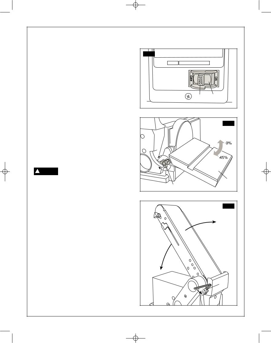
Turning on and off (Fig. 14)
1.To turn the sander ON, push the switch (1) to the right (ON) position.
2.To turn the sander OFF, push the switch to the left (OFF) position.
3.To lock the switch in the OFF position:
a.Wait until the sander has come to a complete stop.
b.Remove the safety key (2) from the switch housing. Store the safety key in a safe place.
4.To unlock the switch and turn the sander ON, insert the safety key into the switch, and move the switch to the ON position.
Bevel sanding (Fig. 15)
1.The work table (3) can be tilted from 0° to 45° for bevel sanding.
2.Loosen the table lock knob (4) and tilt the work table to the desired angle.
3.Retighten the table lock knob.
To avoid trapping the work or ! WARNING fingers between the table and
sanding surface, the table should be repositioned on the table support to retain a maximum of 1-2 mm distance between sanding surface and table.
Positioning belt bed (Fig. 16)
The belt bed locking hex screw (5) locks the belt bed
(6) in a vertical or horizontal position.
To adjust vertical position:
1.Remove work support.
2.Loosen the hex head locking screw (5) using a 6 mm hex wrench.
3.Position belt bed and retighten the hex head locking screw.
FIG. 14 |
|
2 |
1 |
FIG. 15 |
3 |
4 |
FIG. 16 |
5 |
14.
SM 2610957110 05-08 6/5/08 7:36 AM Page 15
Operation
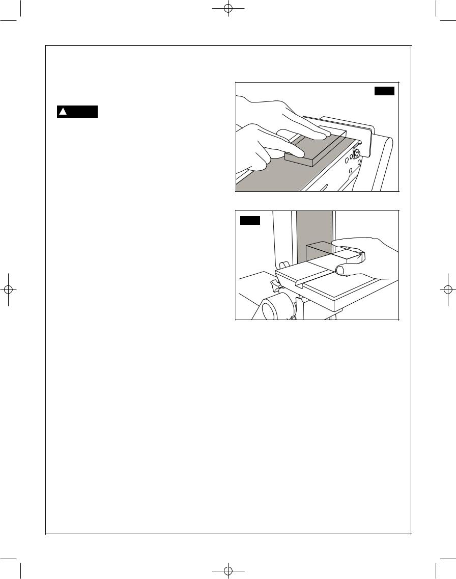
Surface sanding on the sanding belt (Fig. 17)
To avoid injury from slips, jams or ! WARNING thrown pieces, adjust the backstop
to clear the sanding surface by no more than 1-2 mm.
When checking clearance between the belt and work support, press the belt flat against the metal beneath it.
1.Hold the work piece firmly with both hands, keeping fingers away from the sanding belt.
2.Keep the end butted against the backstop and move the work evenly across the sanding belt. Use extra caution when sanding very thin pieces.
3.When sanding long pieces, remove the work support.
4.Apply only enough pressure to allow the sanding belt to remove any material.
End sanding on the sanding belt (Fig. 18)
1.It is more convenient to sand the ends of long workpieces with the sanding belt in a vertical position.
2.Move the work evenly across the sanding belt. For accuracy, use the mitre gauge.
FIG. 17
FIG. 18 |
15.
SM 2610957110 05-08 6/5/08 7:36 AM Page 16
Operation
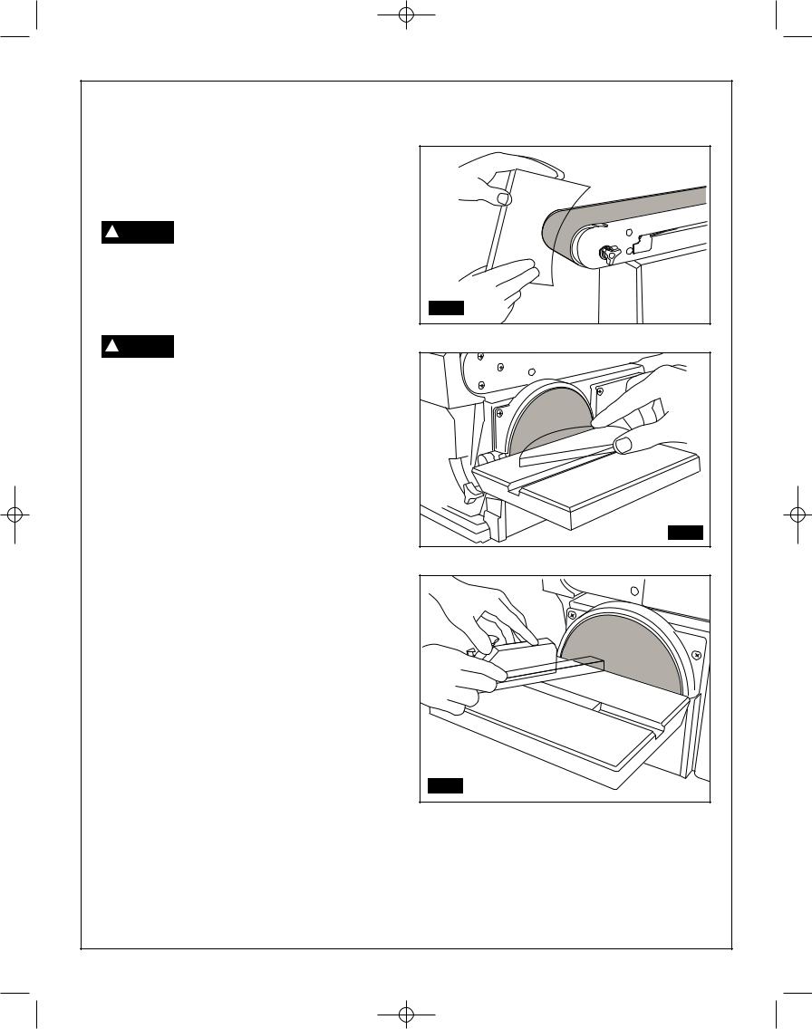
Sanding curved edges (Fig. 19 & 20)
1.Always sand inside curves on idler drum as shown in figure 19.
Never attempt to sand the ends of a ! WARNING workpiece on the idler drum.
Applying the end of the workpiece to the idler drum could cause the work piece to fly up and result in an injury.
2.Always sand outside curves on the left hand side of the sanding disc, as shown in figure 20.
Applying the workpiece to the right ! WARNING side of the disc could cause
workpiece to fly up (kickback) and result in injury.
Sanding small end surfaces on the sanding disc (Fig. 21)
1.Use of the mitre gauge is recommended for this operation.
2.Rest the workpiece against the edge of the mitre gauge.
3.Always move the work across the left hand side of the sanding disc.
FIG. 19 |
FIG. 20 |
4. The table may be tilted for bevelled work.
FIG. 21 |
16.
 Loading...