


 SM 2610028633 01-13_SM 2610028633 01-13.qxp 1/9/13 7:24 AM Page 1
IMPORTANT: |
IMPORTANT : |
IMPORTANTE: |
Read Before Using |
Lire avant usage |
Leer antes de usar |
|
|
|
Operating/Safety Instructions
Consignes d’utilisation/de sécurité
Instrucciones de funcionamiento y seguridad
3386
|
Call Toll Free for |
Pour obtenir des informations et |
Llame gratis para |
|
Consumer Information |
les adresses de nos centres de |
obtener información |
||
|
& Service Locations |
service après-vente, |
para el consumidor y |
|
|
|
appelez ce numéro gratuit |
ubicaciones de servicio |
|
|
|
|||
|
1-877-SKIL999 (1-877-754-5999) www.skil.com |
|
||
|
|
|
|
|
|
|
|
|
|
For English Version |
Version française |
Versión en español |
||
|
See page 2 |
Voir page 20 |
Ver la página 38 |
|
|
|
|
|
|

 SM 2610028633 01-13_SM 2610028633 01-13.qxp 1/9/13 7:24 AM Page 2
General Safety Rules
! |
WARNING |
“READ ALL INSTRUCTIONS” Failure to follow the safety rules listed below and other basic safety |
|
precautions may result in serious personal injury. |
|||
|
|||
|
|
||
|
|
|
Work Area
KEEP CHILDREN AWAY
Do not let visitors contact tool or extension cord. All visitors should be kept safe distance from work area.
KEEP WORK AREAS CLEAN
Cluttered areas and benches invite accidents.
MAKE WORKSHOP KID-PROOF
With padlocks, master switches, or by removing starter keys.
AVOID DANGEROUS ENVIRONMENTS
Don’t use power tools in damp or wet locations. Keep work area well lit. Do not expose power tools to rain. Do not use the tool in the presence of flammable liquids or gases.
Personal Safety
KNOW YOUR POWER TOOL
Read and understand the owner’s manual and labels affixed to the tool. Learn its application and limitations as well as the specific potential hazards peculiar to this tool.
DON’T OVERREACH
Keep proper footing and balance at all times.
STAY ALERT
Watch what you are doing. Use common sense. Do not operate tool when you are tired. Do not operate while under medication or while using alcohol or other drugs.
WEAR PROPER APPAREL
Do not wear lose clothing, gloves, neckties, rings, bracelets, or other jewelry which may get caught in moving parts. Nonslip footwear is recommended. Wear protective hair covering to contain long hair.
ALWAYS USE SAFETY GLASSES
Also use face or dust mask if cutting operation is dusty, and ear plugs during extended periods of operation. Everyday eyeglasses have only impact resistant lenses, they are NOT safety glasses.
GUARD AGAINST ELECTRIC SHOCK
Prevent body contact with grounded surfaces. For example: pipes, radiators, ranges, refrigerator enclosures.
DISCONNECT TOOLS FROM POWER SOURCE
When not in use, before servicing, when changing blades, bits, cutters, etc.
KEEP GUARDS IN PLACE
In working order, and in proper adjustment and alignment.
REMOVE ADJUSTING KEYS AND WRENCHES
When not in use, before servicing, when changing blades, bits, cutters, etc.
REDUCE THE RISK OF UNINTENTIONAL STARTING
Make sure the switch is in the “OFF” position before plugging in tool.
GROUND ALL TOOLS
This tool is equipped with an approved 3-conductor cord and a 3 prong grounding type plug to fit the proper grounding type receptacle. The green conductor in the cord is the grounding wire. Never connect the green wire to a live terminal.
NEVER STAND ON TOOL OR ITS STAND
Serious injury could occur if the tool is tipped or if the cutting tool is accidentally contacted. Do not store materials on or near the tool such that it is necessary to stand on the tool or its stand to reach them.
CHECK DAMAGED PARTS
Before further use of the tool, a guard or other part that is damaged should be carefully checked to ensure that it will operate properly and perform its intended function. Check for alignment of moving parts, mounting, and any other conditions that may affect its operation. A guard or other part that is damaged should be properly replaced.
! WARNING All repairs, electrical or mechanical, should be attempted only by trained repairmen. Contact the nearest Skil Factory Service
Center, Authorized Service Station or other competent repair service.
Use only Skil replacement parts; any others may create a hazard.
The use of any other accessories not specified in the current Skil catalog,
may create a hazard.
“SAVE THESE INSTRUCTIONS”
2.

 SM 2610028633 01-13_SM 2610028633 01-13.qxp 1/9/13 7:24 AM Page 3
Additional Safety Rules
Tool Use
DON’T FORCE TOOL
It will do the job better and safer at the rate for which it was designed.
USE THE RIGHT TOOL
Don’t force a small tool or attachment to do the job of a heavy duty tool. Don’t used tool for purpose not intended—for example, don’t use a circular saw for cutting tree limbs or logs.
SECURE WORK
Use clamps or a vise to hold work. It’s safer than using your hand and it frees both hands to operate the tool.
NEVER LEAVE TOOL RUNNING UNATTENDED
Turn power off. Don’t leave tool until it comes to a complete stop.
Tool Care
DO NOT ALTER OR MISUSE TOOL
These tools are precision built. Any alteration or modification not specified is misuse and may result in dangerous conditions.
AVOID GASEOUS AREAS
Do not operate electric tools in a gaseous or explosive atmosphere. Motors in these tools normally spark, and may result in a dangerous condition.
MAINTAIN TOOLS WITH CARE
Keep tools sharp and clean for best and safest performance. Follow instructions for lubricating and changing accessories. Inspect tool cords periodically and if damaged, have repaired by authorized service facility. Inspect extension cords periodically and replace if damaged. Keep handles dry, clean and free from oil and grease.
Before connecting the tool to a power source (receptacle, outlet, etc.), be sure voltage supplied is the same as that specified on the nameplate of the tool. A power source with a voltage greater than that specified for the tool can result in serious injury to the user, as well as damage to the tool. If in doubt, DO NOT PLUG IN THE TOOL. Using a power source with a voltage less than the nameplate rating is harmful to the motor.
THINK SAFETY
SAFETY IS A COMBINATION OF OPERATOR COMMON SENSE AND ALERTNESS AT ALL TIMES WHEN THE BAND SAW IS BEING USED.
Do not allow familiarity (gained from frequent use of your band saw) to become commonplace. Always remember that a careless fraction of a second is sufficient to inflict severe injury.
3.
The operation of any power tool can result in foreign objects being thrown into the eyes, which can result in severe eye damage.
Always wear safety goggles that comply with ANSI Z87.1 (shown on
Package) before commencing power tool operation.
! |
WARNING |
Some dust created by power |
|
sanding, sawing, grinding, drilling, |
|||
|
|||
|
|
and other construction activities contains chemicals known to cause cancer, birth defects or other reproductive harm. Some examples of these chemicals are:
•Lead from lead-based paints,
•Crystalline silica from bricks and cement and other masonry products, and
•Arsenic and chromium from chemically treated lumber.
Your risk from these exposures varies, depending on how often you do this type of work. To reduce your exposure to these chemicals: work in a well ventilated area, and work with approved safety equipment, such as those dust masks that are specially designed to filter out microscopic particles.
NOTE AND FOLLOW THE SAFETY WARNINGS AND INSTRUCTIONS THAT APPEAR ON THE BAND SAW:

 SM 2610028633 01-13_SM 2610028633 01-13.qxp 1/9/13 7:24 AM Page 4
Specific Safety Rules for Band Saws
1.To avoid injury from unexpected movement, make sure the saw is on a firm, level surface, properly secured to prevent rocking. Make sure there is adequate space for operations. Bolt the saw to a support surface to prevent slipping or sliding during operation.
2.Turn off and unplug the saw before moving it.
3.Use the correct size and style of blade.
4.Make sure the blade teeth point down and toward the table.
5.Blade guide, supports, bearings, and blade tension must be properly adjusted to avoid accidental blade contact and to minimize blade breakage. To maximize blade support, always adjust the upper blade guide and blade guard so that it barely clears the workpiece.
6.The table tilt lock handle should be tight.
7.Use extra caution with very large, very small, or awkward workpieces.
8.Use extra supports to prevent workpieces from sliding off the table top.
9.Workpieces should be secured so they don’t twist, rock, or slip while being cut.
10.Plan intricate or small work carefully to avoid pinching the blade. Avoid awkward operations and hand positions to prevent accidental contact with the blade.
11.Small pieces should be secured with clamps or fixtures. Do not hold small pieces with your hand because your fingers might go under the blade guard.
12.Support round work properly (use a V block or press it against the miter gauge) to prevent it from rolling and the blade from biting.
13.Cut only one workpiece at a time. Make sure the table is clear of everything except the workpiece and its guides before you turn the saw on.
14.Always watch the saw run before each use. If there is excessive vibration, saw blade stuttering, or unusual noise, stop immediately. Turn the saw off. Unplug it immediately. Do not start the saw again until the problem has been located and corrected.
15.To free any jammed material, turn the switch off. Remove the switch key and unplug the saw.
Wait for all moving parts to stop before removing the jammed material.
16.Do not leave the work area until all moving parts have stopped. Shut off the power to master switches. Remove the switch key from the band saw and store it in a safe place, away from children. Childproof the workshop!
17.Maintain proper adjustment of blade tension, blade alignment, blade guides and thrust bearings.
18.Adjust upper guide to 1/8” above workpiece before cutting.
19.Hold workpiece firmly against table.
20.Use recommended blade and speed for workpiece material.
21.Before, starting, be certain the motor, table, attachments and adjustment knobs are secured.
22.Do not operate with wheel cover door open.
23.Unplug saw before making blade changes, adjustments or repairs.
24.Do not expose to rain or use in damp locations.
4.
 SM 2610028633 01-13_SM 2610028633 01-13.qxp 1/9/13 7:24 AM Page 5
Motor Specifications and Electrical Requirements
General Specifications
Voltage Rating . . . . . . . . . . . . . . . . . . . .120 V, 60 Hz
Amperage Rating . . . . . . . . . . . . . . . . . . . . . . . .2.5 A
No Load Speed . . . . . . . . . . . . .No 2800 min (SFPM)
Throat . . . . . . . . . . . . . . . . . . . . . . . . . . .9" (22.9 cm)
Blade Length . .59 1/4” (150.5 cm) - 59 1/2” (151 cm)
Blade Width . . . . . . . .1/8” (0.32 cm) - 3/8” (0.95 cm)
Cutting Capacity . . . . . . . . . . . . . . . . .3 1/2" (8.9 cm)
Table size . . . . . . . . . . . . 11 3/4 x 12" (30 x 30.5 cm)
Motor Specifications
In the event of a malfunction or breakdown, grounding provides a path of least resistance for electric current to reduce the risk of electric shock. This tool is equipped with an electric cord having an equipment-grounding conductor and a grounding plug. The plug must be plugged into a matching outlet that is properly installed and grounded in accordance with all local codes and ordinances.
This Band Saw is designed to use a 1720 RPM motor. It is wired for operation on 110-120 volts, 60 Hz. alternating current. Before connecting the motor cord to power source, make certain the switch is in the “OFF” position and be sure the electric current is of the same characteristics as stamped on the band saw nameplate.
Connection To A Power Source
This machine must be grounded while in use to protect the operator from electric shock.
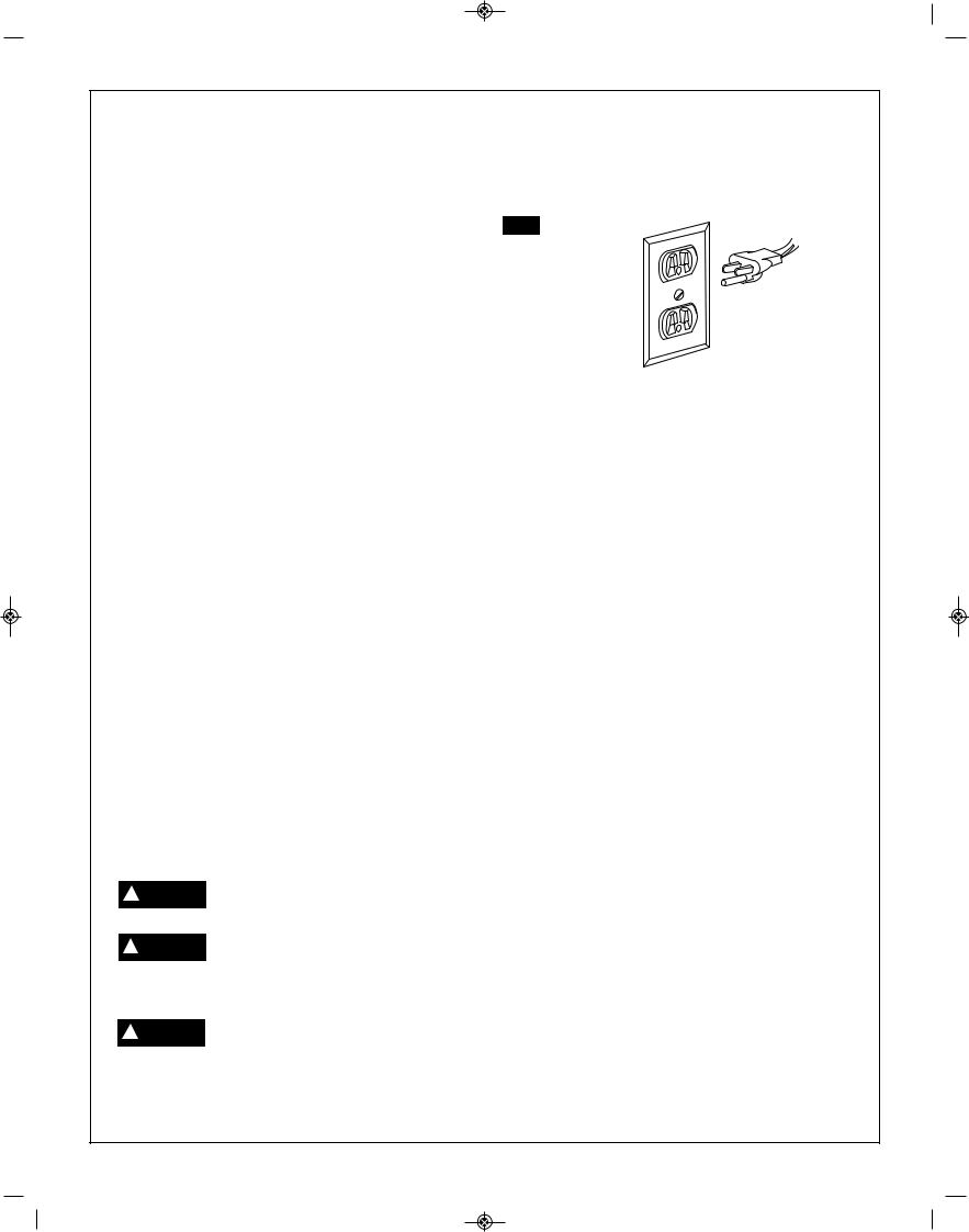
Plug power cord into a 110-120V properly grounded type outlet protected by a 15-amp dual element time delay fuse or circuit breaker.
Not all outlets are properly grounded. If you are not sure that your outlet, as pictured in Fig. A, is properly grounded; have it checked by a qualified electrician.
To avoid electric shock, do not touch ! DANGER the metal prongs on the plug when
installing or removing the plug to or from the outlet.
Failure to properly ground this power ! DANGER tool can cause electrocution or
serious shock, particularly when used near metal plumbing or other metal objects. If shocked, your reaction could cause your hands to hit the tool.
If power cord is worn, cut or damaged in any way, have it replaced
immediately to avoid shock or fire hazard.
Your unit is for use on 120 volts; it has a plug that looks like the one in Figure A.
FIG. A
This power tool is equipped with a 3-conductor cord and grounding type plug, approved by Underwriters Laboratories and the Canadian Standards Association. The ground conductor has a green jacket and is attached to the tool housing at one end and to the ground prong in the attachment plug at the other end.
If the outlet you are planning to use for this power tool is of the two-prong type, DO NOT REMOVE OR ALTER THE GROUNDING PRONG IN ANY MANNER. Have a qualified electrician replace the TWO-prong outlet with a properly grounded THREE-prong outlet.
Improper connection of the equipment-grounding conductor can result in a risk of electric shock. The conductor with insulation having an outer surface that is green with or without yellow stripes is the equipmentconductor. If repair or replacement of the electric cord or plug is necessary, do not connect the equipmentgrounding conductor to a live terminal.
Check with a qualified electrician or service personnel if the grounding instructions are not completely understood, or if in doubt as to whether the tool is properly grounded.
Always use proper extension cord. The use of any extension cord will cause some loss of power. To keep this to a minimum and to prevent overheating and motor burn-out, use the table below to determine the minimum wire size (A.W.G.) extension cord. Use only 3-wire extension cords which have 3-prong grounding type plugs and 3-pole receptacles which accept the tool’s plug. Make sure your extension cord is in good condition.
Extension Cord Length |
Wire Size A.W.G. |
0-25 feet . . . . . . . . . . . . . . . . . . . . . . . . . . . . . . . . . . . .18
26-50 feet . . . . . . . . . . . . . . . . . . . . . . . . . . . . . . . . . .16
51-100 feet . . . . . . . . . . . . . . . . . . . . . . . . . . . . . . . . .16
“SAVE THESE INSTRUCTIONS”
5.

 SM 2610028633 01-13_SM 2610028633 01-13.qxp 1/9/13 7:24 AM Page 6
Table of Contents
|
Page |
|
Page |
General Safety Rules .................................................. |
2 |
Getting To Know Your Band Saw |
........................... 8–9 |
Additional Safety Rules........................................... |
3–4 |
Assembly and Adjustments ................................. |
9-15 |
Motor Specifications and Electrical Requirements ..... |
5 |
Basic Band Saw Operation................................ |
16-18 |
Unpacking and Checking Contents............................. |
7 |
Maintaining Your Band Saw.................................... |
19 |
Table of Loose Parts ................................................... |
7 |
Troubleshooting ...................................................... |
56 |
|
|
|
|
6.

 SM 2610028633 01-13_SM 2610028633 01-13.qxp 1/9/13 7:24 AM Page 7
Unpacking and Checking Contents
To reduce the risk of injury, never ! WARNING connect plug to power source outlet
until all assembly steps are complete and until you |
|
|
have read and understood the entire owner’s |
A |
|
manual. |
||
|
Model 3386 Motorized Band Saw is shipped complete in one box.
1.Unpacking and Checking Contents, separate all parts from packing materials. Check each one with the “Table of Loose Parts” to make sure all items are accounted for before discarding any packing material.
If any parts are missing, do not at- ! WARNING tempt to assemble the band saw, plug
in power cord or turn the switch on until the missing parts are obtained and are installed correctly.
2.Remove the protective oil that is applied to table. Use any ordinary household type grease and spot remover.
To avoid fire or toxic reaction, never use gasoline, naptha or similar highly
volatile solvents.
3.Apply a coat of paste wax to the table to prevent rust. Wipe all parts thoroughly with a clean dry cloth.
B
C
Table of Loose Parts
ITEM |
DESCRIPTION |
QTY. |
|
|
A |
Band Saw |
1 |
|
|
B |
Table |
1 |
|
|
C |
Fence |
1 |
|
|
D |
Miter gauge assembly |
1 |
F |
|
E |
3 mm allen wrench |
1 |
||
|
||||
F |
Table bolt, washer, lock washer |
4 |
|
|
G |
Operating Guide |
1 |
|
Tools Needed
An adjustable wrench, combination square, and a phillips screwdriver will be needed for assembly and adjustments.
G
D
E
7.

 SM 2610028633 01-13_SM 2610028633 01-13.qxp 1/9/13 7:24 AM Page 8
Getting To Know Your Band Saw

 1
1
1 |
Blade tension knob |
|
|
|
2 |
Blade guard |
|
|
11 |
3 |
LED work light |
|
|
|
|
|
|
||
4 |
Blade |
|
|
|
5 |
Table support assembly |
|
|
2 |
6 |
Lower blade guide |
|
|
|
|
|
|
||
7 |
Drive belt |
|
|
|
8 |
Lower wheel |
|
|
|
9 |
Door |
|
|
|
10 |
Wheel brush |
|
|
|
11 |
Upper wheel |
|
|
|
12 |
Blade tracking lock nut |
|
|
10 |
13 |
Blade tracking knob |
9 |
|
4 |
14 |
Motor assembly |
|
6 |
|
|
|
|||
15 |
Base |
|
|
|
16 |
Dust port |
|
|
|
17 |
Table tilt adjustment lock knob |
|
|
|
18 |
Table tilt adjustment knob |
|
|
|
|
1 |
|
|
|
|
23 |
|
|
8 |
|
|
|
|
|
|
|
|
|
7 |
|
24 |
|
|
|
|
3 |
|
|
1 |
26 |
|
|
5 |
|
|
|
|
|
|
|
|
|
|
12 |
|
19 |
|
22 |
13 |
|
|
|
|
|
|
|
|
21 |
|
|
25 |
|
20 |
|
|
|
|
|
|
|
15 |
|
|
|
|
|
|
19 |
|
19 Table |
18 |
20Upper blade guide
21Upper blade guide lock knob
22Upper blade guide adjustment knob
23Upper viewing port
24Upper door knob
25Lower door knob
26ON/OFF switch with safety key
17
16 |
14 |
|
15
8.

 SM 2610028633 01-13_SM 2610028633 01-13.qxp 1/9/13 7:24 AM Page 9
Assembly & Adjustments
Before assembling the band saw, turn ! WARNING off the saw, remove the safety key and
unplug the power cord from the electrical outlet. The power cord must remain unplugged whenever you are working on the saw.
Install the table (Figs. 1–3)
1.Loosen the locking knob (1) and rotate the blade guard knob (2) to raise the upper blade guard (3) to the highest position.
2.Remove table connector (5).
FIG. 1 |
2 |
1 |
3 |
4 |
3.Place the table on the table support by sliding the slot
(6)in the table over the blade (4), taking care not to damage the blade.
4.Align the four holes on the bottom of the table over the four holes in the table support (7).
5.Place a washer and locking washer on each bolt (8) and secure the bolt through the table support and into the table.
6.Tighten all four bolts to make sure the table is fastened securely.
7.Replace table connector (5).
Note: The table must be properly adjusted before operating the saw. See Table tilt adjustment (page 10).
FIG. 2 |
|
5 |
6 |
|
FIG. 3 |
7 |
8 |
9.

 SM 2610028633 01-13_SM 2610028633 01-13.qxp 1/9/13 7:24 AM Page 10
Assembly & Adjustments
Install the fence (Fig. 4)
1.Raise the clamp (1) on the fence assembly to the up position.
2.Place the fence on the table so that the clamp is at the front of the table.
3.Lower the fence clamp to lock the fence in position on the table.
To move the fence, raise the clamp and slide the fence to the desired location. Lower the clamp to lock the fence in position.
Mount the band saw to a work surface (Fig. 5)
Secure the saw to a suitable work surface by inserting the appropriate mounting hardware through the four predrilled holes (2) in the base of the saw.
Adjustments
Before adjusting the band saw, turn ! WARNING off the saw, remove the safety key,
and unplug the power cord from the electrical outlet. The power cord must remain unplugged whenever you are working on the saw.
Table tilt adjustment (Fig. 6)
The table tilts from 0° to 45° to the right.
1.Turn the table tilt lock knob (3) counterclockwise.
2.Turn the table tilt adjustment knob (4) until the pointer is at the desired angle on the table tilt gauge (5).
3.Tighten the table lock knob (3) clockwise to secure the table.
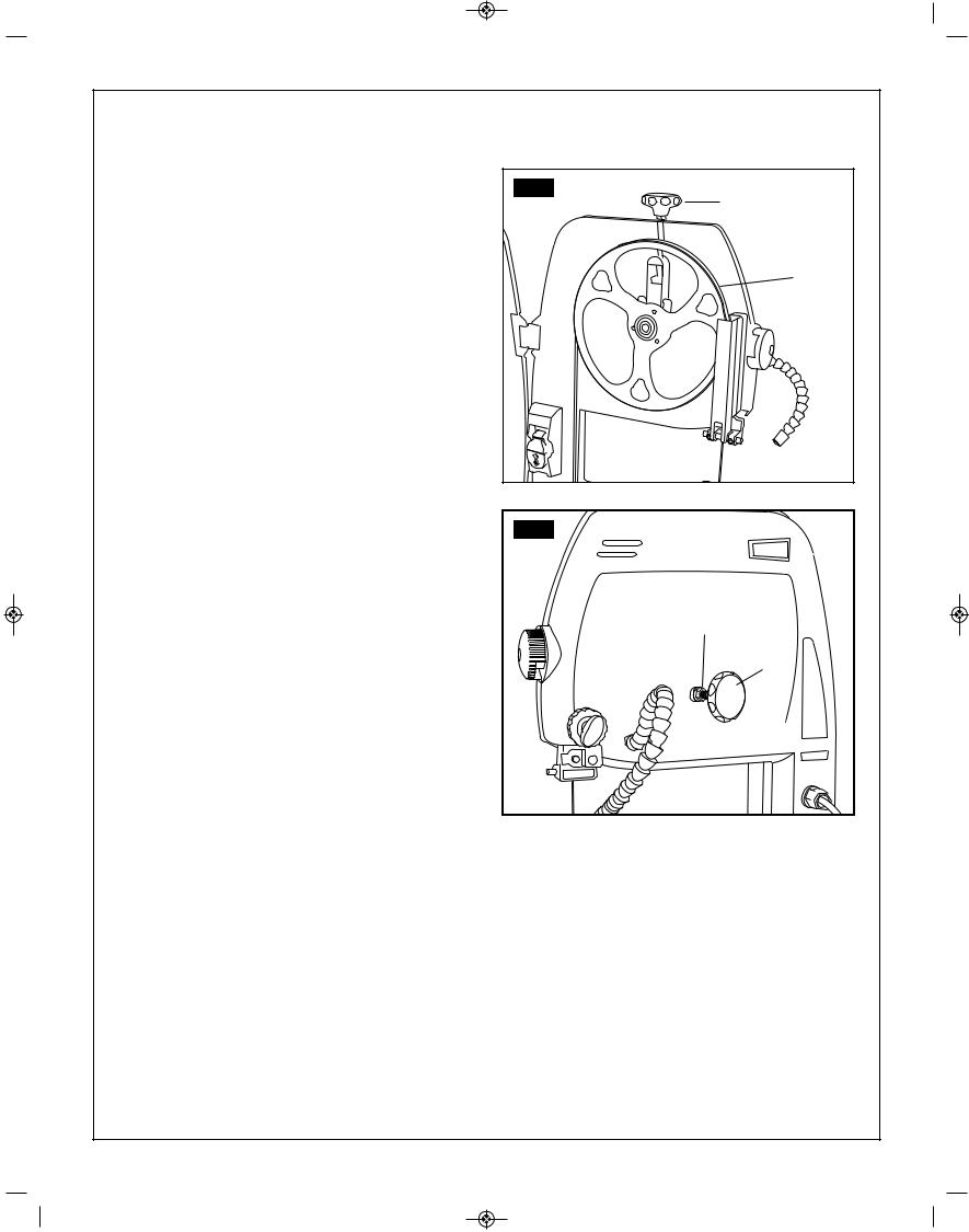
Connect to a dust collection system (Fig. 7)
A 1-1/2" (3.8 cm) dust port (6) is located on the motor side of the band saw. This port can be connected to a dust collection system directly by connecting the pickup end of the dust collection hose to the dust port.
FIG. 4 |
1 |
FIG. 5 |
2 |
2 |
FIG. 6 |
|
4 |
5 |
|
|
|
3 |
FIG. 7 |
6 |
10.
 SM 2610028633 01-13_SM 2610028633 01-13.qxp 1/9/13 7:24 AM Page 11
Assembly & Adjustments
Fence Adjustment (Fig. 8)
The fence is pre-set at the factory, but it may need adjustment over time.
To increase the holding force of the fence to the table, turn the nut (1) on the back of the fence clockwise.
To reduce the holding force of the fence, turn the nut counterclockwise.
When properly adjusted, the fence should hold firmly to the table and the fence lever should pivot down (lock) with reasonable force. Be sure not to over tighten nut, as that may damage the fence lever and reduce the holding force.
Squaring the Sawtable to the Blade (Fig. 9 & 10)
1.Raise and lock the blade guide assembly (1) to its highest position.
2.Place a small combination square (2) on the saw table beside the blade and check squareness of the saw table to the blade.
If an adjustment is needed:
3.Loosen table tilt adjustment lock knob (5).
4.Using a 3 mm hex key (3), adjust zero stop set screw (4) until table is square to blade when set screw makes contact with housing.
5.Tighten table tilt adjustment lock knob (5).
6.Adjust scale indicator (6) by loosening screw with a phillips screwdriver, align scale indicator to zero, then retighten screw.
FIG. 8 |
1 |
FIG. 9 |
1 |
3 |
2 |
4 |
FIG. 10 |
6 |
5 |
11.
 SM 2610028633 01-13_SM 2610028633 01-13.qxp 1/9/13 7:24 AM Page 12
Assembly and adjustments
Blade tension adjustment (Fig. 11)
A change in blade width or type of material being cut will affect the blade tension. If the blade tension is too loose, it will be difficult to cut a straight line. If the blade is too tight, the blade may break or come off the wheel.
1.Turn the blade tension knob (1) clockwise, to raise the upper blade wheel (2) and increase the tension on the blade. The blade should be tight on the wheel, but do not overtighten the blade.
2.Turn the blade tension knob (1) counter-clockwise to lower the upper blade wheel (2) and reduce the tension on the blade.
Blade tracking adjustment (Fig. 11 & 12)
Note: The band saw blade tracking is pre-set at the factory. Check for proper blade tension before making any blade tracking adjustments.
Rotate the upper blade wheel (2) clockwise and check the position of the blade on the wheel. The blade should remain in the center of the wheel.
If an adjustment is needed:
1.Using a wrench, loosen the blade tracking lock nut (3).
2.If the blade moves toward the front edge of the wheel: turn the blade tracking knob (4) slightly
clockwise. At the same time, turn the upper wheel (2) until the blade is centered.
If the blade moves toward the back edge of the wheel: turn the blade tracking knob (4) slightly counter-clockwise. At the same time, turn the upper wheel (2) until the blade is centered.
3.Tighten the blade tracking lock nut (3) when you are finished making adjustments.
4.Check the position of the blade on the lower wheel. If the tracking is off, continue adjusting the blade until it sits properly on both wheels. If blade does not sit properly on wheels, return to blade tension adjustment.
FIG. 11 |
1 |
2 |
FIG. 12 |
3 |
4 |
Blade guide adjustment
The upper and lower blade guides and support bearings (located above and below the table) keep the blade moving in a straight line during operation. These guides must be checked and adjusted before each use, after changing the blade, and after blade tension and tracking adjustment.
Note: Make sure the blade tension and tracking are properly adjusted before adjusting the upper and lower blade guides.
12.
 SM 2610028633 01-13_SM 2610028633 01-13.qxp 1/9/13 7:24 AM Page 13
Assembly and adjustments
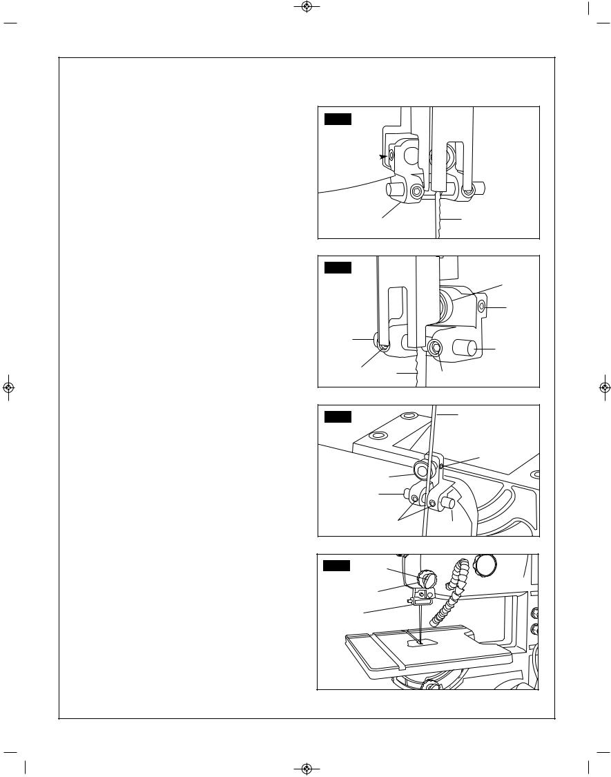
Adjust the upper blade guide (Fig. 13–14)
1.Make sure the upper blade guide assembly (1) is at right-angles to the blade (2).
If not: loosen the screw (3) and rotate the assembly until it is perpendicular to the blade, then re-tighten the screw (3).
2.Loosen the support bearing screw (4) and move the support bearing (5) forward or backward until the bearing is 1/32" (0.8 mm) behind the blade. Tighten the screw (4).
3.Loosen the left and right blade guide screws (6) and move the guides (7) as close to the blade as possible without pinching it. Using a feeler gauge (not provided), make sure the space between each guide and the blade measures 0.02" (0.5 mm). Tighten the screws (6).
Adjust the lower blade guides (Fig. 15)
It is possible to adjust lower blade guide with table attached, however user may find it easier to do so with table removed.
1.Loosen the lower support bearing screw (8). Move the support bearing (9) forward or backward until the bearing is 1/32" (0.8 mm) behind the blade (2).
2.Loosen the lower blade guide screws (10) and move the left and right blade guides (11) as close to the blades as possible without pinching it. Using a feeler gauge (not provided), make sure the space between each guide and the blade measures 0.02" (0.5 mm). Tighten both screws (10).
3.Reattach table (if removed), taking care not to bump the table against the blade.
Set blade guide assembly height (Fig. 16)
The blade guide assembly should be set approximately 1/8" (3.2 mm) above the workpiece.
1.Loosen the blade guide lock knob (1).
2.Rotate the blade guide adjustment knob (2) to lower the blade guide assembly (3).
3.Tighten the blade guide lock knob (1).
FIG. 13
3
1 |
2 |
|
FIG. 14
|
|
|
5 |
|
|
|
4 |
7 |
|
|
|
|
|
|
7 |
|
6 |
2 |
6 |
|
|
||
|
|
|
|
FIG. 15 |
|
|
2 |
|
|
|
|
|
|
|
8 |
|
|
9 |
|
|
|
11 |
|
|
|
10 |
11 |
FIG. 16 |
|
1 |
|
|
|
|
|
|
|
2 |
|
|
3 |
|
|
13.

 SM 2610028633 01-13_SM 2610028633 01-13.qxp 1/9/13 7:24 AM Page 14
Assembly and adjustments
Replace the blade (Fig. 17)
Blade teeth are sharp. Use care when ! WARNING handling a band saw blade.
It is possible to replace the blade with the table in place, however user may find it easier to do so with table removed.
1.Remove the fence from the table.
2.Rotate both the upper and lower door knobs (1) clockwise to open the wheel cover door.
3.Open the blade guard (2).
4.Rotate the blade tension knob (3) counter-clockwise to lower the upper wheel and reduce tension on the blade.
5.Remove the old blade (4). Slide the blade out and away from the upper and lower blade guides (5) (and through the slot in the table if you did not remove it).
6.Put the new blade in position around the upper and lower wheels and between the upper and lower blade guides (5).
Note: The teeth of the blade should be facing downward and facing the front of the tool.
7.Center the blade on the upper and lower wheels. Turn the upper wheel slowly to check the position of the blade.
8.Move the blade tension knob (3) clockwise to increase the tension on the blade.
9.Make sure the blade is still centered on the upper and lower wheels and that it moves freely through the blade guides.
10.The blade must be adjusted properly before operating the saw:
a.See Blade tension adjustment (page 12).
b.See Blade tracking adjustment (page 12).
c.See Blade guide adjustment (page 13).
11.Close blade guard (2).
12.Close wheel cover door by rotating both the upper and lower door knobs (1) counter-clockwise.
13.Reattach table (if removed).
FIG. 17 |
3 |
2 |
1 |
4 |
5 |
1 |
14.

 SM 2610028633 01-13_SM 2610028633 01-13.qxp 1/9/13 7:24 AM Page 15
Assembly and adjustments
Miter gauge adjustment (Fig. 18)
Place the miter gauge in the groove on the table. The miter gauge can be adjusted 0° to 60° right and left to maintain an accurate angle on your workpiece. To adjust the angle on the miter gauge:
1.Turn the miter gauge knob (1) counterclockwise to loosen.
2.Rotate the base of the gauge to align the pointer (2) with the desired angle.
3.Tighten the miter gauge knob (1).
Wheel brush adjustment (Fig. 19)
The wheel brush is located against the lower blade wheel and helps keep the blade clean of sawdust and wood chips.
If an adjustment is needed:
1.Loosen the screw (3) that secures the wheel brush (4).
2.Position the wheel brush against the wheel.
3.Tighten the screw.
Drive belt adjustment (Fig. 19 & 20)
Check the deflection of the drive belt (5) in the center between the two pulleys on the opposite side from the belt tension wheel. The belt should deflect 1/4" (6 mm) deflection when pressing on the drive belt in the center between the two pulleys.
1.Loosen, but do not remove, the two bolts (6) that hold the motor assembly to the housing.
2.To reduce the tension on the belt: pull the motor assembly (7) up (counterclockwise).
To increase tension on the belt: push the motor assembly down (clockwise).
3.Tighten the two bolts that hold the motor to the housing.
FIG. 18
1
2 
3
4
FIG. 19 |
5 |
|
|
|
6 |
|
|
7 |
|
6 |
FIG. 20 |
15.
 SM 2610028633 01-13_SM 2610028633 01-13.qxp 1/9/13 7:24 AM Page 16
Operation
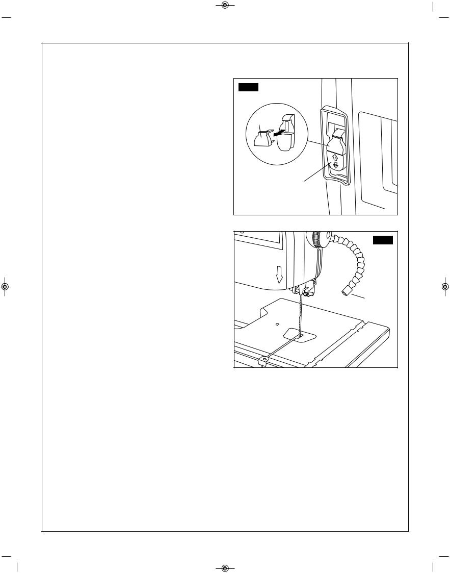
ON/OFF switch (Fig. 21)
1.To turn the saw ON, move the switch (1) to the up (ON) position.
2.To turn the saw OFF, move the switch to the down (OFF) position.
3.To lock the switch in the OFF position:
a.Wait until the band saw has come to a complete stop.
b.Remove the safety key (2) from the switch housing. Store the safety key in a safe place.
4.To unlock the switch and turn the saw ON, insert the safety key into the switch, and move the switch to the ON position.
LED work lamp (Fig. 22)
The LED work lamp (3) has an adjustable gooseneck for precision control when aiming the light.
FIG. 21
2
1
FIG. 22 |
3 |
16.

 SM 2610028633 01-13_SM 2610028633 01-13.qxp 1/9/13 7:24 AM Page 17
Operation
|
|
General cutting |
|
|
|
Use scrap lumber to check the |
|
! |
WARNING |
||
settings and to get the feel of |
|||
|
|
|
operating the band saw before attempting regular work.
•Do not turn the power on before all adjustments have been made. Check to make sure the upper guide is in place. Always keep the upper blade guide close to your work, approximately 1/8" (3.2 mm) above the workpiece.
•Do not force the workpiece against the blade. Light contact permits easier cutting and prevents unwanted friction and heating of the blade.
•Sharp saw blades need little pressure for cutting. Steadily move the workpiece against the blade without forcing it.
Use the band saw for straight line operations such as cross-cutting, ripping, miter cutting, beveling, compound cutting, and resawing.
To avoid twisting the blade, do not turn sharp corners; instead, saw around corners.
A band saw is basically a “curve-cutting” saw. It is not capable of doing intricate inside cutting as can be done with a scroll saw.
Do not use this band saw to cut ! WARNING ferrous metals.
When backing out the workpiece, the blade may bind in the kerf (cut). This is usually caused by sawdust clogging the kerf or when the blade comes out of the guides. If this happens:
•Place the switch in the OFF position. Wait until the saw has come to a complete stop, then remove the switch key from the switch assembly. Store key in a safe place.
•Unplug the saw from the power source.
•Wedge the kerf open with a flat screwdriver or wooden wedge.
•Open front cover and turn the upper wheel by hand while backing out the workpiece.
Cutting curves
When cutting curves, carefully turn the workpiece so the blade follows without twisting. If the curve
is so sharp that you repeatedly back up and cut new kerf, use a narrower blade, or a blade with more set (teeth further apart). When a blade has more set, the workpiece turns easier but the cut is rougher.
When changing a cut, do not withdraw the workpiece from the blade. The blade may get drawn off the wheels. To change a cut, turn the workpiece and saw out through the scrap material area.
When cutting long curves, make relief cuts as you go along.
Circle cutting (Fig. 23)
1. Adjust the upper blade guard to 1/8" (3.2 mm) above the workpiece.
2. Use both hands while feeding the work into the blade. Hold the workpiece firmly against the table.
Use gentle pressure. Do not force the work, allow the blade to cut.
3. The smallest diameter circle that can be cut is determined by the width of the blade. For example, a 1/4" (6.4 mm) wide blade will cut a minimum diameter of approximately 1 1/2" (38.1 mm).
FIG. 23 |
76.2 |
Minimum Circle Diameter |
Minimum Radius |
Blade Width |
|
|
|
|
|
1 |
1/2” (12.7 mm) |
1/4” (6.4 mm) |
1/8” (3 mm) |
|
|
|
|
2 |
1” (25.4 mm) |
1/2” (12.7 mm) |
3/16” (4.7 mm) |
|
|
|
|
3 |
1-1/2” (38.1 mm) |
3/4” (19.05 mm) |
1/4” (6.4 mm) |
|
|
|
|
4 |
3” (76.2 mm) |
1-1/2” (38.1 mm) |
3/8” (9.5 mm) |
|
|
|
|
|
|
17. |
|
 SM 2610028633 01-13_SM 2610028633 01-13.qxp 1/9/13 7:24 AM Page 18
Operation (continued)
Blade selection
! WARNING Blade teeth are sharp. Use care when handling a band saw blade.
For longest wear and best cutting results, use the correct blade thickness, width, and temper for the type of material you will cut.
When sawing small curves and delicate work, use narrow blades. Otherwise, use the widest blade possible. For cutting wood and similar materials with this band saw, purchase blades in widths up to 3/8" (9.5 mm), and a length of 59 1/4” or 59 1/2" (150.5 or 151 mm).
Do not cut ferrous metals with this band saw.
Common causes of blade breakage:
•Poor guide alignment and adjustment.
•Forcing or twisting a wide blade around a short radius.
•Feeding too fast.
•Dull teeth or not enough set.
•Too much blade tension.
•Setting top guide assembly too high above the workpiece.
•Lumpy or improperly finished braze or weld on the blade.
•Continuous running of blade when not cutting.
|
|
|
|
|
|
|
Operation |
Recommended Blade Width |
|
||
|
|
Inches |
Millimeters |
|
|
|
Cross Cutting |
1/4, 3/8 |
6.4, 9.5 |
|
|
|
Miter Cutting |
1/4, 3/8 |
6.4, 9.5 |
|
|
|
Beveling |
1/4, 3/8 |
6.4, 9.5 |
|
|
|
Compound Cutting |
1/4, 3/8 |
6.4, 9.5 |
|
|
|
Circle Cutting |
See Fig. 23 |
See Fig. 23 |
|
|
|
Curve Cutting |
1/8, 1/4 |
3.2, 6.4 |
|
|
|
|
|
|
|
|
18.
 Loading...