


Owner’s Manual
Guide d’utilisation
Manual del propietario
Model/ Modelo/ Modèle: RT1322-00
14 Amp Plunge and Fixed Base Router
Toupie à base fixe et en plongée de 14 A
Rebajadora de 14 amperios con base fija y base de penetración
 WARNING: To reduce the risk of injury, the user must read and understand the Owner’s Manual before using this product. Save these instructions for future reference.
 AVERTISSEMENT : Afin de réduire les risques de blessure, l’utilisateur doit lire et comprendre le guide d’utilisation avant d’utiliser cet article. Conservez le présent guide afin de pouvoir le consulter ultérieurement.
 ADVERTENCIA : Para reducir el riesgo de lesiones, el usuario debe leer y comprender el Manual del operador antes de utilizar este producto. Guarde estas instrucciones para consultarlas en caso sea necesario.
For Customer Service
Pour le service à la clientèle 1-877-SKIL-999 OR www.skil.com
Servicio al cliente

TABLE OF CONTENTS |
|
General Power Tool Safety Warnings. . . . . . . . . . . . . . . . . . . . . . . . . . . . |
. . 3-4 |
Safety Warnings for Router . . . . . . . . . . . . . . . . . . . . . . . . . . . . . . . . . . . . |
. . 5-6 |
Symbols. . . . . . . . . . . . . . . . . . . . . . . . . . . . . . . . . . . . . . . . . . . . . . . . . . . . |
. . 7-9 |
Get to Know Your Router. . . . . . . . . . . . . . . . . . . . . . . . . . . . . . . . . . . . . . |
10-11 |
Specifications. . . . . . . . . . . . . . . . . . . . . . . . . . . . . . . . . . . . . . . . . . . . . . . |
. . . 11 |
Operating Instructions. . . . . . . . . . . . . . . . . . . . . . . . . . . . . . . . . . . . . . . . |
12-30 |
Maintenance. . . . . . . . . . . . . . . . . . . . . . . . . . . . . . . . . . . . . . . . . . . . . . . . |
31-32 |
Extension Cords. . . . . . . . . . . . . . . . . . . . . . . . . . . . . . . . . . . . . . . . . . . . . |
. . .32 |
Troubleshooting . . . . . . . . . . . . . . . . . . . . . . . . . . . . . . . . . . . . . . . . . . . . . |
. . .32 |
Limited Warranty of SKIL Consumer Tools. . . . . . . . . . . . . . . . . . . . . . . . . . |
33 |
 WARNING
•Some dust created by power sanding, sawing, grinding, drilling and other construction activities contains chemicals known to the State of California to cause cancer, birth defects or other reproductive harm. Some examples of these chemicals are:
––Lead from lead-based paints.
––Crystalline silica from bricks, cement, and other masonry products. ––Arsenic and chromium from chemically-treated lumber.
•Your risk from these exposures varies, depending upon how often you do this type of work. To reduce your exposure to these chemicals:
––Work in a well-ventilated area.
––Work with approved safety equipment, such as dust masks that are specially designed to filter out microscopic particles.
––Avoid prolonged contact with dust from power sanding, sawing, grinding, drilling, and other construction activities. Wear protective clothing and wash exposed areas with soap and water. Allowing dust to get into your mouth or eyes or to lie on the skin may promote absorption of harmful chemicals.
2

GENERAL POWER TOOL SAFETY WARNINGS
WARNING Read all safety warnings, instructions, illustrations and specifications provided with this power tool.. Failure to follow all instructions listed
below may result in electric shock, fire and/or serious injury.
SAVE ALL WARNINGS AND INSTRUCTIONS FOR FUTURE REFERENCE..
The term “power tool” in the warnings refers to your mains-operated (corded) power tool or battery-operated (cordless) power tool.
Work area safety
Keep work area clean and well lit. Cluttered or dark areas invite accidents.
Do not operate power tools in explosive atmospheres, such as in the presence of flammable liquids, gases or dust. Power tools create sparks which may ignite the dust or fumes.
Keep children and bystanders away while operating a power tool.. Distractions can cause you to lose control.
Electrical safety
Power tool plugs must match the outlet.. Never modify the plug in any way.. Do not use any adapter plugs with earthed (grounded) power tools.. Unmodified plugs and matching outlets will reduce risk of electric shock.
Avoid body contact with earthed or grounded surfaces, such as pipes, radiators, ranges and refrigerators.. There is an increased risk of electric shock if your body is earthed or grounded.
Do not expose power tools to rain or wet conditions.. Water entering a power tool will increase the risk of electric shock.
Do not abuse the cord.. Never use the cord for carrying, pulling or unplugging the power tool.. Keep cord away from heat, oil, sharp edges or moving parts.. Damaged or entangled cords increase the risk of electric shock.
When operating a power tool outdoors, use an extension cord suitable for outdoor use..
Use of a cord suitable for outdoor use reduces the risk of electric shock.
If operating a power tool in a damp location is unavoidable, use a ground fault circuit interrupter (GFCI) protected supply.. Use of a GFCI reduces the risk of electric shock.
Personal safety
Stay alert, watch what you are doing and use common sense when operating a power tool. Do not use a power tool while you are tired or under the influence of drugs, alcohol or medication.. A moment of inattention while operating power tools may result in serious personal injury.
Use personal protective equipment. Always wear eye protection. Protective equipment such as a dust mask, non-skid safety shoes, hard hat or hearing protection used for appropriate conditions will reduce personal injuries.
Prevent unintentional starting.. Ensure the switch is in the off-position before connecting to power source and/or battery pack, picking up or carrying the tool..
Carrying power tools with your finger on the switch or energising power tools that have the switch on invites accidents.
Remove any adjusting key or wrench before turning the power tool on.. A wrench or a key left attached to a rotating part of the power tool may result in personal injury.
Do not overreach.. Keep proper footing and balance at all times.. This enables better control of the power tool in unexpected situations.
3

Dress properly.. Do not wear loose clothing or jewellery.. Keep your hair and clothing away from moving parts.. Loose clothes, jewellery or long hair can be caught in moving parts.
If devices are provided for the connection of dust extraction and collection facilities, ensure these are connected and properly used.. Use of dust collection can reduce dustrelated hazards.
Do not let familiarity gained from frequent use of tools allow you to become complacent and ignore tool safety principles. A careless action can cause severe injury within a fraction of a second.
Power tool use and care
Do not force the power tool.. Use the correct power tool for your application.. The correct power tool will do the job better and safer at the rate for which it was designed.
Do not use the power tool if the switch does not turn it on and off.. Any power tool that cannot be controlled with the switch is dangerous and must be repaired.
Disconnect the plug from the power source and/or remove the battery pack, if detachable, from the power tool before making any adjustments, changing accessories, or storing power tools.. Such preventive safety measures reduce the risk of starting the power tool accidentally.
Store idle power tools out of the reach of children and do not allow persons unfamiliar with the power tool or these instructions to operate the power tool.. Power tools are dangerous in the hands of untrained users.
Maintain power tools and accessories.. Check for misalignment or binding of moving parts, breakage of parts and any other condition that may affect the power tool’s operation.. If damaged, have the power tool repaired before use.. Many accidents are caused by poorly maintained power tools.
Keep cutting tools sharp and clean.. Properly maintained cutting tools with sharp cutting edges are less likely to bind and are easier to control.
Use the power tool, accessories and tool bits etc.. in accordance with these instructions, taking into account the working conditions and the work to be performed.. Use of the power tool for operations different from those intended could result in a hazardous situation.
Keep handles and grasping surfaces dry, clean and free from oil and grease.. Slippery handles and grasping surfaces do not allow for safe handling and control of the tool in unexpected situations.
|
When using power tools, basic safety precautions should always be |
|
WARNING |
||
|
followed to reduce the risk of fire, electric shock, and personal injury. |
|
|
||
|
The operation of any tool can result in foreign objects being propelled into |
|
WARNING |
||
your eyes, resulting in severe eye damage. When operating power tool, |
||
|
always wear safety goggles or safety glasses with side shields and a full face shield when needed.
|
If any parts are missing, do not operate the tool until the missing parts |
WARNING |
|
|
have been replaced. Doing so could result in serious personal injury. |
|
Service
Have your power tool serviced by a qualified repair person using only identical replacement parts.. This will ensure that the safety of the power tool is maintained.
If any part of this router is missing or should break, bend, or fail in any way; or should any electrical component fail to perform properly: shut off the power switch and remove the plug from the power source and have the missing, damaged, or failed parts replaced before resuming operation.
4
SAFETY WARNINGS FOR ROUTER
Hold the power tool by insulated gripping surfaces only, because the cutter may contact its own cord.. Cutting a “live” wire may make exposed metal parts of the power tool “live” and could give the operator an electric shock.
Use clamps or another practical way to secure and support the workpiece to a stable platform.. Holding the work by your hand or against the body leaves it unstable and may lead to loss of control.
Maintain a firm grip on the router with both hands to resist starting torque.
Never attempt to use the router motor without first installing it in an approved fixed base.. Failure to heed this warning could result in personal injury and damage to the motor.
Make sure that the motor housing does not move up or down when clamped in the fixed base. If the motor is not securely clamped into the base, injury could result and adjustments will not be accurate..
Do not hand-hold the router in an upside down or horizontal position.. The motor can separate from the base if not properly attached according to the instructions.
Tighten the collet/nut securely to prevent the cutter bit from slipping.. If the collet/nut is not securely tightened, the cutter bit may detach during use, causing serious personal injury.
Never tighten the collet/nut without a cutter bit installed in the collet/nut..
Never hold the piece being cut in your hands or across your legs.. It is important to support and clamp the workpiece properly in order to minimize body exposure, bit binding, or loss of control.
Always keep the chip shield clean and in place..
Stay alert and clear the router cutter bit path of any obstructions before starting the motor.. Keep cutting area clear of all foreign objects while the motor is running.
Inspect and remove all nails from lumber before routing..
Check to see that the cord will not “hang up” during routing operation..
Make sure that the cutter bit is not in contact with the workpiece before the switch is turned on.. The bit must always be running at full speed before contacting the workpiece..
Keep hands clear of the cutter bit when the motor is running to prevent personal injury. Provide clearance under the workpiece for the router cutter bit when through-cutting.
Keep cutting pressure constant.. Do not overload the motor.
Use only sharp cutter bits that are not chipped or cracked. Blunt cutter bits will cause stalling and burn the workpiece.
Never use this router motor with a cutter bit larger than 3-1/2 inches in diameter..
Always use cutter bits that are designed for this router.. Never use cutter bits which are larger in diameter than the opening in the router sub-base.. Cutter bits that have cutter diameters larger than the opening could cause possible loss of control or create other hazardous condition that could cause serious personal injury.
The sub-base on this router has an opening of 1-1/4 inches.. To use cutter bits with a larger diameter, install and use a sub-base with a larger diameter opening.
Do not use large router cutter bits for freehand routing.. Use of large cutter bits when freehand routing could cause loss of control or create hazardous conditions that could result in serious personal injury. If using a router table, large bits should be used for edging only.
Be sure that the cutter bit is centered in a template guide (sold separately) prior to template guide applications to avoid personal injury or damage to finished work.
Do not remove more than 1/8 inch in a single pass.. Excessive depth of cut can result in loss of control that could result in personal injury.
5

After completing a cut, turn the motor OFF and let it come to complete stop before removing router from workpiece.. Let the motor come to a complete stop before putting the router down.. Cutter bits coast after the power is turned off.
Only use router tables with on-board switch-controlled receptacles.. Failure to use router tables with all the appropriate safety features could result in serious personal injury.
Disconnect the tool from the power source before making any adjustments or changing cutter bits.
If you are changing a bit immediately after use, be careful not to touch the collet/nut or cutter bit with your hands or fingers. The heat buildup from cutting could cause severe burns. Always use the wrench provided.
Avoid “climb cutting;” see “Feeding the Router” section in this manual.. “Climb cutting” increases the chance for loss of control resulting in possible serious injury.
Only use router bits suitable for the no-load speed of the tool..
Never use router bits with a diameter exceeding the maximum diameter specified in the technical data section..
 WARNING
 WARNING
Bits, sockets, and tools get hot during operation. Wear gloves when touching them.
Wear ear protection. Exposure to noise can cause hearing loss.
|
To avoid injury, hold the tool by the insulated gripping surfaces only. If the |
WARNING |
|
|
tool contacts hidden wiring or its own cord, exposed metal parts of the tool |
|
could shock the operator and cause serious injury. Make sure that hidden electrical wiring, water pipes, or other hazards are not in the cutting path.
6
SYMBOLS
Safety Symbols
The purpose of safety symbols is to attract your attention to possible dangers. The safety symbols and the explanations with them deserve your careful attention and understanding. The symbol warnings do not, by themselves, eliminate any danger. The instructions and warnings they give are no substitutes for proper accident prevention measures.
WARNING Be sure to read and understand all safety instructions in this Operator’s Manual, including all safety alert symbols such as “DANGER,”
“WARNING,” and “CAUTION” before using this tool. Failure to following all instructions listed below may result in electric shock, fire, and/or serious personal injury.
The definitions below describe the level of severity for each signal word. Please read the manual and pay attention to these symbols.
|
|
|
|
|
This is the safety alert symbol. It is used to alert you to potential |
|
|
|
|
|
personal injury hazards. Obey all safety messages that follow this |
|
|
|
|
|
symbol to avoid possible injury or death. |
|
|
|
|
|
DANGER indicates a hazardous situation which, if not avoided, will |
|
|
DANGER |
|||
|
|
|
|
|
result in death or serious injury. |
|
|
|
|
|
|
|
|
|
|
|
|
|
|
|
|
WARNING indicates a hazardous situation which, if not avoided, could |
|
|
|
WARNING |
|||
|
|
|
|
|
result in death or serious injury. |
|
|
|
|
|
|
|
|
|
|
|
|
|
|
|
|
CAUTION, used with the safety alert symbol, indicates a hazardous |
|
|
|
CAUTION |
|||
|
|
|
|
|
situation which, if not avoided, will result in minor or moderate injury. |
|
|
|
|
|
|
|
|
|
|
|
|
Damage Prevention and Information Messages
These inform the user of important information and/or instructions that could lead to equipment or other property damage if they are not followed. Each message is preceded by the word “NOTICE”, as in the example below:
NOTICE: Equipment and/or property damage may result if these instructions are not followed.
|
The operation of any power tools can result in foreign |
|
WARNING |
||
objects being thrown into your eyes, which can result |
||
|
in severe eye damage. Before beginning power tool operation, always wear safety goggles or safety glasses with side shields and a full face shield when needed. We recommend a Wide Vision Safety Mask for use over eyeglasses or standard safety glasses with side shields.Always use eye protection which is marked to comply withANSI Z87.1.
7

SYMBOLS (CONTINUED)
IMPORTANT: Some of the following symbols may be used on your tool. Please study them and learn their meaning. Proper interpretation of these symbols will allow you to operate the tool better and safer.
Symbol |
Name |
Designation/Explanation |
||||||
|
|
V |
Volts |
Voltage (potential) |
||||
|
|
A |
Amperes |
Current |
||||
|
|
|
|
|
|
|
|
|
|
Hz |
Hertz |
Frequency (cycles per second) |
|||||
|
W |
Watt |
Power |
|||||
|
kg |
Kilograms |
Weight |
|||||
|
|
|
|
|
|
|
|
|
min |
Minutes |
Time |
||||||
|
|
|
|
|
|
|
|
|
|
|
s |
Seconds |
Time |
||||
Ø |
|
|
Diameter |
Size of drill bits, grinding wheels, etc. |
||||
|
|
|
|
|
|
|
|
|
|
n0 |
No load speed |
Rotational speed, at no load |
|||||
|
|
n |
Rated speed |
Maximum attainable speed |
||||
…/min |
Revolutions or reciprocation |
Revolutions, strokes, surface speed, |
||||||
per minute |
orbits, etc. per minute |
|||||||
|
|
|
|
|
|
|||
0 |
|
|
Off position |
Zero speed, zero torque... |
||||
|
|
|
|
|
|
|
|
|
1,2,3,… |
Selector settings |
Speed, torque or position settings. Higher |
||||||
I,II,III, |
number means greater speed |
|||||||
|
||||||||
|
|
|
|
|
|
Infinitely variable selector |
Speed is increasing from 0 setting |
|
|
|
|
|
|
|
with off |
||
|
|
|
|
|
|
|
||
|
|
|
|
|
|
Arrow |
Action in the direction of arrow |
|
|
|
|
|
|
|
|||
|
|
|
|
|
|
|
|
|
|
|
|
|
|
|
Alternating current |
Type or a characteristic of current |
|
|
|
|
|
|
|
Direct current |
Type or a characteristic of current |
|
|
|
|
|
|
|
|||
|
|
|
|
|
|
|
|
|
|
|
|
|
|
|
Alternating or direct current |
Type or a characteristic of current |
|
|
|
|
|
|
|
|||
|
|
|
|
|
|
|
|
|
|
|
|
|
|
|
Class II tool |
Designates Double Insulated Construction |
|
|
|
|
|
|
|
tools. |
||
|
|
|
|
|
|
|
||
|
|
|
|
|
|
Earthing terminal |
Grounding terminal |
|
|
|
|
|
|
|
|||
|
|
|
|
|
|
|
|
|
|
|
|
|
|
|
Li-ion RBRC seal |
Designates Li-ion battery recycling |
|
|
|
|
|
|
|
program |
||
|
|
|
|
|
|
|
||
|
|
|
|
|
|
|
|
|
|
|
|
|
|
|
Ni-Cad RBRC seal |
Designates Ni-Cad battery recycling |
|
|
|
|
|
|
|
program |
||
|
|
|
|
|
|
|
||
|
|
|
|
|
|
|
|
|
8

Symbol |
Name |
Designation/Explanation |
|
|
|
|
Read manual symbol |
Alerts user to read manual |
|
|
|
|
Wear eye protection symbol |
Alerts user to wear eye protection |
|
|
|
SYMBOLS (CERTIFICATION INFORMATION)
IMPORTANT: Some of the following symbols for certification information may be used on your tool. Please study them and learn their meaning. Proper interpretation of these symbols will allow you to operate the tool better and safer.
Symbol Designation/Explanation
This symbol designates that this tool is listed by Underwriters Laboratories.
This symbol designates that this tool is recognized by Underwriters
Laboratories.
This symbol designates that this tool is listed by Underwriters
Laboratories, to United States and Canadian Standards.
This symbol designates that this tool is listed by the Canadian
Standards Association.
This symbol designates that this tool is listed by the Canadian
Standards Association, to United States and Canadian Standards.
This symbol designates that this tool is listed by the Intertek Testing
Services, to United States and Canadian Standards.
This symbol designates that this tool complies to NOM Mexican
Standards.
9

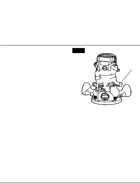
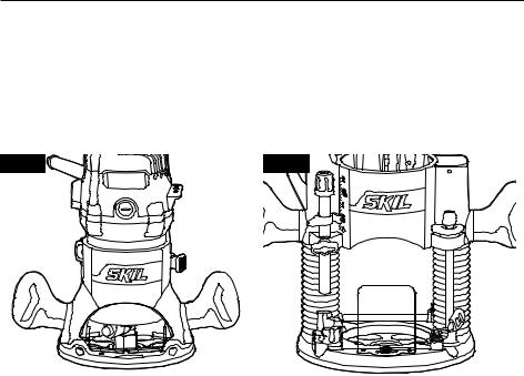
GET TO KNOW YOUR ROUTER
Fig. 1 |
Motor-housing Top Cap |
|
|
“Live Tool Indicator” |
|
Light |
Variable-Speed |
|
Selection Chart |
|
Motor Housing |
|
|
Fixed Base |
|
|
Handle |
|
Spindle-lock |
Chip Shield |
|
Button |
|
|
|
Non-Marring Sub-Base |
|
|
Self-Releasing Collets/Nuts System |
|
Digital Display |
|
|
ON/Off Toggle |
Replaceable |
|
Switch |
||
Carbon |
||
Fine-Adjustment |
Brushes |
|
Dial |
|
|
Coarse-Adjustment |
Motor Clamp |
|
|
||
Knob |
|
|
Edge-Guide |
|
|
Lever |
Edge-Guide |
|
Edge Guide |
||
Mounting |
||
Mounting Slot |
Slot |
|
|
Vacuum port |
10
Fine-Adjustment Dial
Plunge-Depth
Locking Lever 
Depth-Rod
Locking Knob
Depth Rod
Depth-Stop
Turret
Quick-release
Lever
Vacuum Port
Depth Scale
Pin
Plunge Base
Clear Plastic
Chip Shield
Quick-release
Lever
Edge-Guide
Mounting Slot
Non-Marring
Sub-Base
SPECIFICATIONS
Power Input |
120V~,60Hz,14A |
No-Load Speed |
10,000-25,000 RPM |
Collet Capacities |
1/4 in. and 1/2 in. |
Sub-Base Opening (Diameter for |
1-1/4 inches (for both bases) |
cutter bit use) |
|
11
OPERATING INSTRUCTIONS
Selecting the Cutter Bit
This router comes with a 1/2” collet and 1/4” collet sleeve that accept cutter bits with 1/2” and 1/4” shanks, respectively. The 1/2” collet is installed on the tool, and the 1/4” collet sleeve can be installed inside the 1/2” collet.
|
Do not use a router cutter bit that has a cutter bit diameter larger |
WARNING |
|
|
than 1-1/4 inches with the sub-bases that are supplied with this router. A |
larger cutter bit will not fit through the sub-base opening, will cause damage to the sub-base and the motor, and could cause serious personal injury to the operator.
|
Always turn the motor off and unplug the router before making any |
WARNING |
|
|
adjustments or installing accessories. Failure to unplug the router could |
|
result in accidental starting, which can cause serious personal injury.
Install the 1/4” Collet Sleeve (figs 2a and 2b)
1.Disconnect the plug from the power supply.
2.Remove the router motor housing from the fixed base or the plunge base.
NOTICE: See the instructions for installing and removing the motor housing from the fixed base or plunge base in this manual.
3.Set the router motor upside down on the motor-housing top cap with the collet pointing up.
4.Press the spindle-lock button to engage and lock the spindle shaft and the 1/2” collet. Place the wrench (included) on the 1/2” collet and turn it counterclockwise to loosen the collet slightly to accept the 1/4” collet sleeve (fig 2a).
5.Insert the 1/4” collet sleeve into the 1/2” collet assembly as far as it will go (fig 2b).
6.With the 1/4” collet sleeve inserted and the spindle-lock button pressed in to engage the shaft, place the wrench on the 1/2” collet and turn it clockwise until the 1/4” collet sleeve is tightened in it.
Fig. 2a |
1/2” Collet |
Fig. 2b |
1/4” Collet
Sleeve
Spindle-lock
Button
Remove the 1/4” Collet Sleeve
1.Disconnect the plug from the power supply.
2.With the spindle-lock button pressed in to engage the shaft, place the wrench on the 1/2” collet and turn it counter-clockwise to loosen the collet slightly to remove the 1/4” collet sleeve.
12
Installing and Removing the Cutter Bit
Installing the Cutter Bit
1.Turn the motor off and unplug the router from the power source.
2.Remove the motor housing from the fixed or plunge base.
NOTICE: See the instructions for installing and  removing the motor housing from the fixed or
  plunge base in this manual.
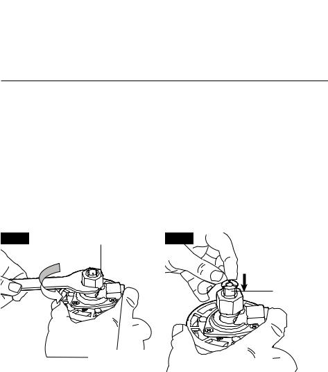
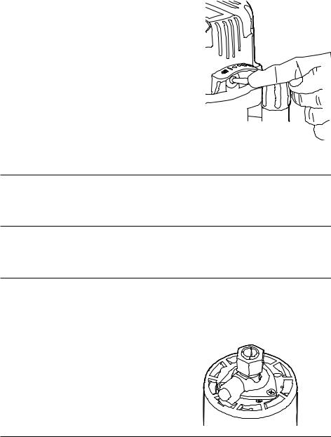
3.Set the motor upside down on the motorhousing top cap, with the collet/nut pointing up.
Fig. 3
Nut
Collet Spindle-lock
Button
4.Press the spindle-lock button to engage and lock the spindle shaft and collet/nut (Fig. 3).
5.Place the wrench on the collet/nut and turn it counterclockwise to loosen the collet/nut
slightly so that it can accept the cutter bit shank.
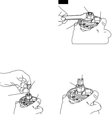
6.Insert the cutter bit shank into the collet/nut assembly as far as it will go, then back the shank out until the cutters are approximately 1/8 to 1/4 inch away from the face of the collet/ nut (Fig. 3a, 3b).
|
|
|
Fig. 3a |
Fig. 3b |
Cutters
Cutters
Collet/Nut
Spindle-lock
 Button
Bit Shank
NOTICE: To ensure proper gripping of the cutter-bit shank and minimize run-out, the shank of the cutter bit must be inserted into the collet/nut at least 5/8 inch.
7.With the cutter bit inserted and the spindle-lock button pressed in to engage the shaft, place the wrench on collet/nut and turn it clockwise until the collet/nut is firmly tightened on the cutter-bit shank.
|
Tighten the collet/nut securely to prevent the cutter bit from slipping. If the |
WARNING |
|
|
collet/nut is not securely tightened, the cutter bit may detach during use, |
|
causing serious personal injury.
NOTICE: To prevent damage to the tool, do not tighten the collet/nut without a cutter bit installed.
Removing the Cutter Bit
1.Turn the motor off and unplug the router from the power source.
2.Remove the motor housing from the fixed or plunge base.
13

NOTICE: See the instructions for installing and removing the motor housing from the fixed or plunge base in this manual.
3.Set the motor housing upside down on the motor-housing top cap, with the collet/nut pointing up.
4.Press the spindle-lock button to engage and lock the spindle shaft and the collet/nut (Fig. 3).
5.Place the wrench on the collet/nut and turn it counterclockwise to loosen the collet/nut slightly; remove the cutter bit shank.
Collet/Nut Care
Before each use, inspect the collet/nut to make sure that it is clean and that it is gripping the cutter bit properly.
With the router cutter bit removed, press the spindle-lock button and turn the collet/nut counterclockwise until it is free from the motor spindle shaft. Blow the collet with compressed air, and clean the tapered inside of the collet/nut with a tissue or a fine brush.
Always make sure that the cutter-bit shank, collet/nut, and motor spindle are clean and free of woodchips, dust, residue, grease, and rust before installing a cutter bit or collet/nut.
Apply a slight amount of machine oil to the spindle shaft if it looks dry. Replace a worn or damaged collet/nut immediately.
NOTICE: The collet/nut is self-releasing; it is not necessary to strike the collet/nut to free the router cutter bit. If the cutter bit seems to be stuck after use, loosen collet/nut a little more until it releases.
Cutter Bits
For faster, more accurate cutting results, keep cutter bits clean and sharp. Remove all accumulated pitch and gum from cutter bits after each use.
When sharpening cutter bits, sharpen only the inside of the cutting edge. Never grind the outside diameter. Be sure, when sharpening the end of a cutter bit, to grind so that the clearance angle is the same as was originally ground.
Installing and Removing the Router Motor Housing
|
Never use the router motor without installing it into either an approved |
WARNING |
|
|
fixed or plunge base. Failure to do so could result in serious personal injury |
|
and damage to the motor.
NOTICE: Before installing the motor housing in the fixed or plunge base, have the collet/nut and router cutter bit you are going to use already installed in motor housing. See “Installing and Removing the Cutter Bit”.
|
Always turn the motor off and unplug the router from the power source |
WARNING |
|
|
before making any adjustments or installing accessories. Failure to turn |
|
the motor off and unplug the router could result in accidental starting, which can cause serious personal injury.
14
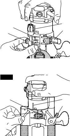
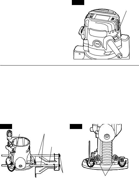
To Install Motor Housing in Fixed Base |
|
Fig. 4 |
|
(Fig.. 4) |
|
|
1.Turn the router motor off and unplug the router from the power source.
2.Place the fixed base on a flat surface.
3.With the back of the fixed base facing you, |
|
C |
|
open the motor clamp (A). |
D |
||
A |
|||
4.Press in the coarse-adjustment knob (B) |
|||
B |
|||
while you align the motor slot (C) with the pin |
|
||
(D) in the fixed base. |
|
|
5.When the motor’s slot is aligned and engaged into the base’s pin, slide the motor down into the fixed base.
6.The router motor will now slide up or down to set coarse adjustments when the coarse-
adjustment knob is pressed in.
7.After all adjustments are made, close the motor clamp securely.
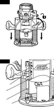
To Install Motor Housing in Plunge Base (Fig.. 5)
1.Turn the motor off and unplug the router from the power source.
2.Place the plunge base on a flat surface.
3.With the back of the plunge base facing you, open the motor clamp (A) and make sure that the plunge action is in the “UP” position and the plunge depth locking lever (B) is locked.
4.With the motor housing slot (C) aligned with the plunge base pin (D), lower the motor housing into the plunge base, engaging the pin into the slot.
5.Slide the motor into the base as far as it will go.
6.Close the motor clamp securely.
Fig. 5
A |
C |
|
B |
D |
|
To Remove the Motor Housing from the Fixed Base (Fig.. 4)
1.Turn the motor off and unplug the router from the power source.
2.Place the router (fixed base and motor housing) on a flat surface.
3.With the back of the router facing you, open the motor clamp (A).
4.Push in the coarse-adjustment knob (B) to release the motor slot (C) from the pin (D) in the fixed base, while you lift the router motor free of the fixed base.
5.Set the motor housing upside down on the motor-housing top cap with the collet pointing up and remove the cutter bit.
To Remove the Motor Housing from the Plunge Base (Fig.. 5)
1.Turn the motor off and unplug the router from the power source.
2.Place the router (plunge base and motor housing) on a flat surface.
3.With the back of the plunge base facing you, open the motor clamp (A) and make sure that the plunge action is in the “UP” position with the plunge depth locking lever (B) locked.
4.Lift the motor straight up out of the base, sliding the motor housing “slot” (C) free from the pin in the plunge base.
15
5.Set the motor housing upside down on the motor-housing top cap with the collet pointing up and remove the bit.
|
Always remove the cutter bit from collet/nut when the router is not being |
|
WARNING |
||
|
used. Leaving bits installed could result in accidents causing serious |
|
personal injury. |
||
|
||
|
||
Adjusting the Depth of Cut |
||
|
Your router should never be turned on or be connected to the power |
|
WARNING |
||
|
source when you are assembling parts, making adjustments, installing or |
|
|
||
removing collets/nuts, cutter bits, cleaning the product, or when it is not in use. Disconnecting the router will prevent accidental starting, which could cause serious personal injury.
Depth Adjustment With Fixed Base (FIG.. 6)
Notice: All depth adjustments on the fixed base must be made with the motor clamp open.
Notice: For all fixed base routers, the cutter bit depth equals the amount of the cutter that is exposed below the surface of the sub-base.
The fixed base is designed with a micrometerfine adjustment system. When the bit is lowered to the approximate position desired (coarse setting), the system then can be microadjusted to the precise depth required.
Coarse Adjustment
Fig. 6
A
C 


D 


B
Depressing the coarse-adjustment knob (B) allows you to quickly lower or raise the cutter bit to an approximate depth setting.
Fine Adjustments
NOTICE: Be sure that the micrometer-fine adjustment system is engaged before making fine adjustments. Test it by turning the fine-adjustment dial (C) clockwise and counter-clockwise to see if the bit lowers and raises.
The depth-indicator ring (D) located on the fine-adjustment dial is marked in 1/256inch increments. Turning the fine-adjustment dial counterclockwise 180° (1/2 turn), lowers the cutter bit 1/32 inch. One full turn counterclockwise 360° (zero “0” to zero “0”) lowers the bit 1/16 inch.
NOTICE: The depth-indictor ring (D) may be reset to zero “0” without moving the fineadjustment dial. This allows the user to begin adjustments from any reference point desired.
NOTICE: Making a single, deep cut is never advisable. Smaller diameter cutter bits are easily broken by too much side thrust and torque. Larger cutter bits will cause a rough cut and be difficult to guide and control. For these reasons, do not exceed 1/8-in. depth of cut in a single pass.
16
Depth Adjustment With The Plunge Base
Plunging Action |
Fig. 7 |
The plunge base feature simplifies the depth adjustments and allows the cutter bit to be accurately lowered down into the workpiece for more precise set-ups.
To lower the cutter bit, release the plungedepth locking lever by moving it “Up” to the unlocked position. Apply an even, downward pressure on the plunge action until the cutter
bit reaches the desired depth, then move the plunge-depth locking lever “Down” to the locked position. (Fig. 7)
To raise the bit and the plunge action, unlock the plunge-depth locking lever and the plunge action will automatically retract from the
workpiece and return to the raised position.
NOTICE: Always have the plunge action in the raised position and locked when the bit is not cutting in the workpiece.
Plunge Action with Depth Rod and Depth-Stop Turret (Fig.. 8)
The depth rod and the depth-stop turret are used to control the plunge action cutting depth as follows:
1.Turn the motor off and unplug the router from the power source.
2.Place the router on a flat, level surface.
3.With the cutting bit already installed, lower the plunge action until the cutter bit makes contact with the flat, level surface on which the router is sitting. Lock the plunge-depth locking lever (F). This position is zero “0”: the point from which further depth adjustments can be made.
Fig. 8 F
E
D
C
B
A
4.To set a desired depth-of-cut, rotate the depth-stop turret until either appropriate selected step of the turret (A) is aligned directly under the depth rod (B). Loosen the depth-rod locking knob (C) and lower the depth rod until it contacts the selected step on the turret.
5.Slide the clear plastic depth indicator (D) until the red line on the indicator is lined up with ZERO - “0” marked on the bottom of the depth scale. (This is now indicating point at which the bit makes contact with the workpiece).
6.To set a desired cutting depth, slide the depth rod up until the red line on the clear plastic depth indicator points to your desired cutting depth on the depth scale (E). Secure the depth rod at this position by tightening the depth-rod locking knob (C).
7.Unlock the plunge-depth locking lever (F) to allow the bit to automatically retract to the up position.
8.The desired depth-of-cut may now be achieved by plunging the router down until the depth rod contacts the selected step on the depth-stop turret.
NOTICE: When making depth adjustments on the plunge base, the motor clamp should always be closed securely.
17
Using the Depth-Stop Turret to Set Up Deep Cuts (Fig.. 9)
NOTICE: Making a single, deep cut is never advisable. Smaller diameter cutter bits are easily broken by too much side thrust and torque. Larger cutter bits will cause a rough cut and be difficult to guide and control. For these reasons, do not exceed 1/8-in. depth of cut in a single pass.
To produce deep cuts, always make several progressively deeper cuts by starting with the highest step on the depth-stop turret, and, after each cut, rotate the turret to the next lower step until the lowest step is reached.
Fig. 9
A
B 


C 


Each of the steps progresses by 1/4 inch increments. The 4 steps represent a total of “0”
inch to 3/4-inch with a full 360º rotation of the turret. Repeat this process if necessary.
Micro-adjustments with the Depth Rod and Depth-Stop Turret (Fig.. 9)
The depth rod has a fine-adjustment knob (A) that turns a screw (B) (inside the rod) either clockwise or counterclockwise to lower or raise the depth rod on the turret (C) for micro-fine adjustments of the plunge depth.
Each complete revolution of the fine adjustment knob adjusts the plunging depth by approximately 1/32 inch.
A reference indicator line is embossed into the depth rod under the fine-adjustment knob to set a reference point of “0”.
When micro-adjusting the plunge depth, always make sure that the fine-adjustment knob has been turned down (clockwise) several revolutions from the top before setting the depth rod and depth-stop turret.
Always set your micro-adjustments with the plunge action locked in the raised, (or up) position.
To use the fine-adjustment knob after the depth rod and turret have been set, check the final depth setting and micro-adjust as follows:
•To micro-increase the plunge depth, raise the fine-adjustment knob by turning the knob counterclockwise the desired amount.
•To micro-reduce the plunge depth, lower the fine-adjustment knob by turning the knob clockwise the desired amount.
18
Toggle “On/Off” Switch |
|
Fig. 10 |
Use the toggle switch located on the top cap of the motor housing to turn the router “ON” and “OFF”.
The left side of the toggle switch hood (as you face it) is marked “I” for “On” and the right side (as you face it) is marked “O” for “Off”.
To turn the motor “ON”, push the toggle switch to the left side marked “I”, or “On”. To turn the motor “OFF” push the toggle switch to the right side marked “O”, or “Off”.
Contact the workpiece with the router and cutter bit only after the router has reached full speed. Turn the router motor “OFF” and allow the cutter bit to come to a complete stop before
removing the router and cutter bit from the workpiece.
Soft-Start Feature
The soft-start feature minimizes torque twist, customary in larger router motors, by limiting the speed at which the motor starts. This increases the motor’s life.
Electronic Feedback Control
The electronic feedback control maintains a constant speed under load to provide a smooth finish.
|
|
LED Worklights (Fig.. 11) |
Fig. 11 |
|
Your router motor has 3 built-in worklights, located around the collet/nut, to provide high visibility of workpiece when cutting. These lights are always “On” when the toggle switch is in the “On” position.
19
“Live Tool Indicator” Light |
Fig. 12 |
"Live Tool |
(Fig.. 12) |
|
Indicator" Light |
Your router also has a “Live Tool Indicator” |
|
|
green light, located on the motor housing top |
|
|
cap where the power cord enters the motor |
|
|
housing. This green light is always on when |
|
|
router motor is plugged into power source. |
|
|
Edge Guide
The router kit includes an edge guide. This edge guide can be used as an aid in routing applications such as decorative edging, straight-edge planing and trimming, grooving, dadoing, and slotting.
To assemble the edge guide, insert two edge-guide rods into the holes on the edge guide, and then use two screws (included) to lock the edge-guide rods in place.
To attach the edge guide to the fixed or plunge base, simply insert the edge-guide rods into the edge-guide mounting slots either from the left or the right. Adjust the edge guide to the desired position.
For fixed base, secure the edge guide by turning the edge-guide levers toward two handles
(Fig.13a); for plunge base, secure the edge guide by turning two edge-guide levers toward the right hand (Fig.13b).
Fig. 13a Edge Guide |
Edge Guide |
Fig. 13b |
Lever |
Rods |
|
|
Edge Guide |
|
LOCK |
Screws |
LOCK |
LOCK |
|
Edge Guide Levers |
||
|
|
|
20
NOTICE:
a.If the inner screws on the fixed base wear down or become loose, tighten the inner screws:
•Pull the edge-guide lever up to strip from the hex nut of the inner screw, turn the edgeguide lever clockwise (for the right edge guide lever) or counterclockwise (for the left
edge guide lever) then push the edge-guide lever down (Fig.14).
•Turn the lever counterclockwise (for the right edge-guide lever) or clockwise (for the left edge-guide lever) to secure the edge-guide rod.
b.If the inner screws on the plunge base wear down or loosen, to tighten the inner screws:
•Pull the edge-guide lever up to strip from the hex nut of the inner screw, turn the edgeguide lever clockwise (for the left edge guide lever) or counterclockwise (for the right edge guide lever) then push the edge-guide lever down (Fig.15).
•Turn the edge-guide lever counterclockwise (for the left edge guide lever) or clockwise (for the right edge guide lever) to secure the edge-guide rod.
Fig. 14
Hex Nut of
Inner Screw
Fig. 15
Hex Nut of
Inner Screw
Hex Nut of
Inner Screw
Hex Nut of
Inner Screw
Electronic Variable-Speed Control Fig. 16
NOTICE: The chart below and all the
specifications appear on the display of the router are only for reference for your operation.
The electronic speed control feature allows the motor speed to be matched to the cutter size and material hardness for an improved finish and extended bit life.
Your motor-housing top cap has a “VariableSpeed Selection Chart” located above the “ON/
OFF” toggle switch, to help you determine the correct speed for the cutter bit being used.
Press “SET” to scroll through the settings of the cutter type, cutter size, and the cutting material.
21/4 |
21/2 |
16000RPM |
|
3 |
|
PLASTICS
Press “+” or “-” directly to choose the cutting speed according various materials of workpieces after making above settings.
21

|
Before operating your router follow all safety instructions in this manual. |
WARNING |
|
|
Failure to do so could result in serious personal injury. |
|
NOTICE: Choose the applicable cutting speed according the bit diameter and the material being cut.
Bit |
|
|
|
|
Size |
0-1” |
1.25-2” |
2.25-2.5” |
3-3.5” |
Materials Hardness |
||||
Plastic |
6 |
4 |
3 |
2 |
Softwood |
6 |
4 |
2 |
1 |
Hardwood |
5 |
3 |
2 |
1 |
Reduce the speed when using extra-large bits (cutting diameter of 1 inch or greater), or heavy cutting bits. Changing the rate of feed can also improve the quality of the cut.
DIAL SETTING |
RPM |
APPLICATION |
|
|
|
|
|
1 |
10,000 |
Non-ferrous metal, hardwoods, larger |
|
|
|
||
2 |
11500/13,000 |
||
diameter cutter bits |
|||
3 |
14500/16,000 |
|
|
|
|
|
|
4 |
17500/19,000 |
Softwoods, plastics, countertops, smaller |
|
|
|
||
5 |
20500/22,000 |
||
diameter cutter bits |
|||
6 |
23500/25,000 |
|
|
|
|
|
The speed charts above indicate the relationship between speed settings and the cutting application. Exact settings are determined by operator experience and preference, and also by recommendations made by manufacturers of cutter bits.
Placing the Router onto the Workpiece and Starting the Cut
|
Before operating the router follow all safety instructions in this manual. |
WARNING |
|
|
Failure to do so could result in serious personal injury. |
|
NOTICE: Making test cuts is essential with most routing applications. A test cut will give a feel for the set-up, the router’s speed, the depth of cut, and how the cutter bit reacts to the workpiece.
Much of routing is a trial-and-error process of making various adjustments, followed by test cuts. To avoid ruining good material, make your test cuts on scrap materials.
How you place your router onto a workpiece (starting the cut) with a fixed base depends on the type of routing you are going to produce: edge routing or internal routing, as discussed on the following pages.
For ease of operation and to maintain proper control, your router has two handles: one on each side of the router base. When operating the router, always hold it firmly with both hands.
|
Always be alert and watch what you are doing. Never operate the router |
WARNING |
|
|
when you are fatigued. |
|
|
|
|
22
Deep Cuts
The proper cutting depth for each pass is always determined by the material, the cutter-bit size and type, and power of the motor.
Always make several progressively deeper cuts: start at one depth and then make several passes, each time increasing the cutting depth, until your desired depth is reached.
Making a cut that is too deep will stress the router motor and the cutter bit, and it may burn the workpiece and dull the cutter bit. It could also “grab” too much of the workpiece and cause you to lose of control of the router, causing a serious accident.
To be certain that your depth settings are correct, always make test cuts in scrap material similar to your workpiece before beginning the final cutting operation.
Remember, knowing the right depth for each cut comes with routing experience.
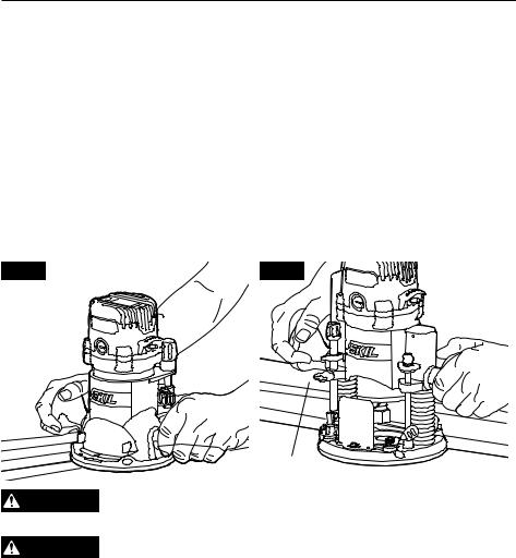
Edge Routing or Internal Routing
For ease of operation and to maintain proper control, your router has two handles, one on each side of the router base. When operating the router, always hold it firmly with both hands (Fig. 16 and 16a).
Edge Routing (Figs.. 16a and 16b)
1.With the depth-of-cut set, place the router on the edge of workpiece, making sure that the cutter does not contact the workpiece. With the plunge base, lock the plunge action in the DOWN position, ready to cut.
2.Clamp an edge guide (board or metal straightedge) in place to help guide the router base.
3.Turn the router “On”, and allow the motor to reach the selected speed.
4.To begin your cut, gradually feed the cutter bit into the edge of the workpiece.
5.When the cut is complete, turn motor “Off” and allow cutter bit come to a complete stop before removing it from the workpiece.
6.Unplug the router from the power source, and inspect the finished cut in the workpiece.
Fig. 16a |
Fig. 16b |
|
Edge Guide |
WARNING |
Always securely clamp your workpiece and keep a firm grip on the router |
|
base with both hands at all times. Failure to do so could result in loss of |
control, causing possibly serious personal injury. |
|
WARNING |
Removing the cutter bit from the workpiece while it is still rotating could |
|
damage the workpiece and result in loss of control, causing serious |
personal injury.
23
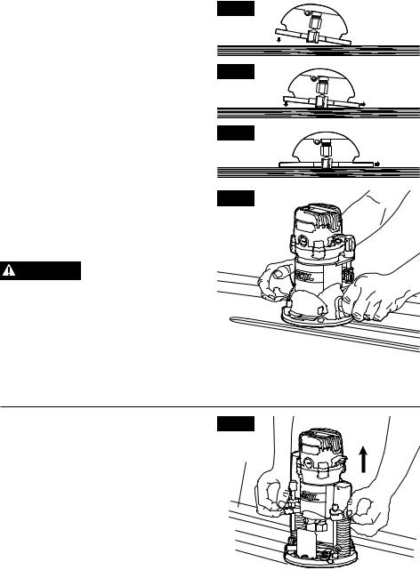
Internal Routing with Fixed Base (Figs.. 17, 17a, 17b and 18)
1.With the depth-of-cut set, tilt the router and place it on the workpiece with only the leading edge of the sub-base contacting the workpiece (Fig. 17).
2.Turn the motor “On” and allow motor build up to its full speed, being careful not to let the cutter bit contact workpiece.
3.To begin your cut, gradually lower the cutter bit into the workpiece until the sub-base is flush with the workpiece (see Fig. 17a, 17b).
4.When the cut is completed, turn the motor “Off” and allow the cutter bit come to a complete stop before removing it from the workpiece.
5.Unplug the router from the power source, place the router upside down on the worktable, and inspect the finished cut in the workpiece.
WARNING Always securely clamp your workpiece and keep a firm
grip on the router base with both hands at all times. Failure to do so could result in loss of control, causing possible serious personal injury. If using a router table, large cutter bits should be used for edging only.
Fig. 17
Fig. 17a
Fig. 17b
Fig. 18
Routing
|
Removing the cutter bit |
WARNING |
|
|
from the workpiece while it |
|
is still rotating could damage the workpiece
and result in loss of control, causing serious personal injury.
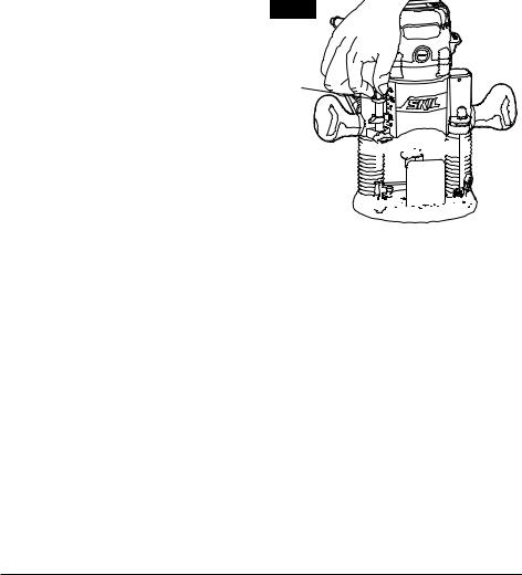
Internal Routing with Plunge Base
1.With the depth-of-cut set, and the plunge action locked in the raised (Up) position, turn the motor “ON” and let the motor build up to its full selected speed (Fig. 19).
2.To begin your cut, unlock the plunge-depth locking lever and gently lower the plunge action evenly into the workpiece.
3.When the desired depth-of-cut is achieved, lock the plunge-depth locking lever (Down) and proceed to make your cut.
4.When the cut is completed, turn the motor “OFF” and allow the cutter bit to come to a complete stop.
Fig. 19 |
Plunge Up |
|
Edge
Guide

 Feed Direction
5.When the cutter bit comes to a complete
stop, unlock the plunge-depth locking lever (Up) and the plunge action will automatically retract the cutter bit from workpiece.
24
|
Removing the cutter bit from the workpiece while it is still rotating could |
|
WARNING |
||
|
damage the workpiece and result in loss of control, causing serious |
|
personal injury. |
||
|
6.Unplug the router from the power source, place the router on worktable, and inspect the finished cut in the workpiece.
WARNING Always securely clamp the workpiece in place, and keep a firm grip on the router base with both hands at all times. Failure to do so could result in
loss of control, causing serious personal injury.
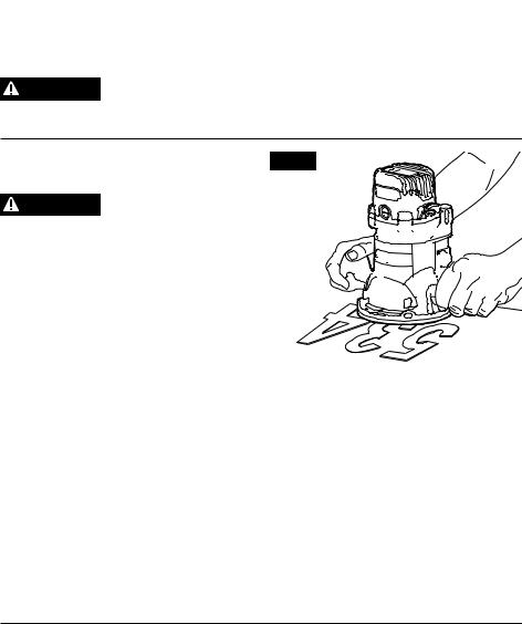
Freehand Routing with the Fixed Fig. 20 Base (Fig.. 20)
WARNING Do not use large cutter bits for freehand routing.
Use of large cutter bits when freehand routing 


 could cause loss of control or create other


 hazardous conditions that could result in


 personal injury. If using a router table, large


 bits should be used for edging only.


When used freehand, the router becomes a flexible and versatile tool. This flexibility makes
it possible to easily rout signs, relief sculptures,
etc. When freehand routing:
1.Draw or lay out the pattern on the workpiece.
2.Choose the appropriate bit.
3.Follow the instructions for INTERNAL ROUTING, and route the pattern in two or more passes. Do not exceed 1/8-in. depth of cut in a single pass. This will help provide better control, as well as serve as a guide on the next passes.
NOTICE: A core-box bit or V-groove bit is often used for routing letters and engraving objects. Straight bits and ball mills are often used to make relief carvings. Veining bits are used to carve small, intricate details.
NOTICE: Making a single deep cut is never advisable. Smaller-diameter bits are easily broken by too much side thrust and torque. Larger bits will cause a rough cut and be difficult to guide and control. For these reasons, do not exceed 1/8- in. depth of cut in a single pass.
|
Always securely clamp your workpiece in place, and keep a firm grip on |
WARNING |
|
|
the router base with both hands at all times. Failure to do so could result in |
|
loss of control causing possible serious personal injury.
25
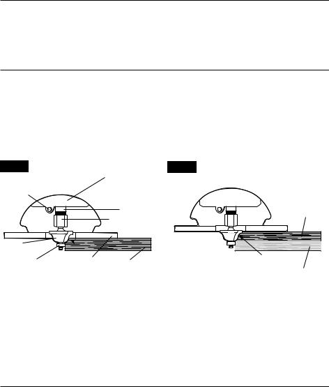
Edging with a Pilot Bit (Figs.. 21a and 21b)
The arbor-type bits with pilots are excellent for edge shaping any workpiece edge that is straight, or is curved at a curvature equal to or greater than the radius of the bit to be used.
The pilot prevents the bit from making an excessively deep cut, and holding the pilot firmly in contact with the workpiece edge throughout prevents the cut from becoming too shallow.
Top-Edge Shaping
Whenever the workpiece thickness, together with the desired depth of cut (as adjusted by router depth setting) are such that only the top part of the edge is to be shaped (leaving at least a 1/16 in. thick uncut portion at the bottom), the pilot can ride against the uncut portion, which serves to guide it (Fig. 21a).
Whole-Edge Shaping
If the workpiece is too thin or the bit is set so low that there will be no uncut edge against which to ride the pilot, an extra board must be placed under the workpiece to act as a guide (Fig. 21b). This “guide” board must have exactly the same contour, “straight or curved”, as the workpiece edge. If it is positioned so that its edge is flush with the workpiece edge, the bit will make a full cut (in as far as the bit radius). On the other hand, if the guide is positioned (out from the workpiece edge), the bit will make less than a full cut, which will alter the shape of the finished edge.
Fig. 21a |
Motor Housing |
Fig. 21b |
|
|
|
Spindle Lock |
|
|
Spindle |
Workpiece |
|
Collet/Nut |
||
|
Cutter-bit |
|
|
Whole Edge of Workpiece |
|
Pilot |
Fixed Base |
Work-piece |
||
Guide Board |
||||
|
Sub-base |
|
||
TOP EDGE SHAPING |
|
WHOLE EDGE SHAPING |
||
NOTICE: The size (diameter) of the pilot that is used determines the maximum cut width that can be made with the pilot against the workpiece edge (a small pilot exposes all of the bit; a large pilot reduces this amount by 1/16 in.).
Any of the piloted cutter bits can be used without a pilot for edge shaping with guides.
|
Always securely clamp your workpiece and keep a firm grip on the router |
WARNING |
|
|
base with both hands at all times. Failure to do so could result in loss of |
|
control causing possible serious personal injury.
26
Feeding the Router (Fig.. 22)
The secrets to professional routing are a careful set-up for the cut, selecting the proper depth of cut, knowing how the cutter bit reacts in your workpiece, and the rate and direction of feed of the router.
The cutter bit rotates clockwise.
NOTICE: When installed in a router table, the direction of rotation will be counterclockwise and other planning is required.
Direction of Feed-External Cuts
Feeding the bit from left to right will cause the bit to pull the router towards the workpiece (Fig. 22).
Fig. 22
External Cuts
FIRST |
|
|
GRAINS |
TATION |
ROUTER FEED |
|
- |
Internal |
|
BIT RO- |
cuts |
|
|
|
ROUTE END |
|
DIRECTION |
|
|


 ROUTER FEED DIRECTION
If the router is fed in the opposite direction (right to left), the rotating force of the cutter bit will tend to throw the bit away from the workpiece. This is called “Climb-Cutting.” “Climb-Cutting” may cause loss of control, possibly resulting in personal injury. When “Climb-Cutting” is required (e.g., backing around a corner), exercise extreme caution to maintain control of the router.
The high speed of the cutter bit during a proper feeding operation (left to right), results in very little kickback under normal conditions. However, if the cutter bit strikes a knot, an area of hard grain, or a foreign object, “Kickback” may result. Kickback may damage your workpiece and could cause you to lose control of the router, possibly causing personal injury. Kickback is always in the opposite direction of the clockwise cutter bit rotation, or counterclockwise.
To guard against and help prevent Kickback, plan your set-up and direction of feed so that you’re always keeping the sharp edges of the cutter bit biting straight into uncut wood. Always inspect your workpiece for knots, hard grain, and foreign objects.
|
Kickback causes the power tool to jerk back toward the user, causing |
WARNING |
|
|
possible loss of control and serious injury. Always take precautions against |
|
kickback as described in the operator’s manual.
27
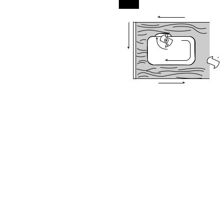
Direction of FeedInternal Cuts (Figs.. 23a and 23b)
When making an internal cut, such as a groove, dado, or slot, always have the guide you are using with the router (edge guide, straight edge, or board guide) on the right-hand side of the router as you make the cut (Fig.23a).
When the guide is positioned on the right hand side of the router, the router travel should be from left to right and “counterclockwise” around curves (see Fig. 23a).
This counterclockwise action around the curve could cause “Climb cutting”. Always be alert and exercise extreme caution to maintain control of the router when making this type of cut around curves.
When the guide is positioned as shown in Fig. 23b, the router travel should be from left to right and clockwise around curves.
If there is a choice, the set-up in Fig. 23a is easier to use, but there is the possibility of “Climb Cutting” around curves. In either case, Fig. 23a or Fig. 23b, the sideways thrust of the router cutting is always against the guide, as is proper.
Fig. 23a |
GUIDE OUTSIDE |
Fig. 23b |
GUIDE INSIDE |
|
|
|
|
|
|||
Bit Rotation |
|
|
|
||
|
|
Thrust |
Bit Rotation |
|
|
|
|
Guide |
|
Thrust |
|
|
|
|
|
||
Bit Rotation |
|
|
Bit Rotation |
|
|
|
|
|
|
|
|
Router Feed |
|
Guide |
|
|
|
Direction |
|
Router Feed Direction |
|
||
WARNING |
Always securely clamp the workpiece in place, and keep a firm grip on the |
||||
|
|
router base with both hands at all times. Failure to do so could result in |
|||
loss of control causing possible serious personal injury.
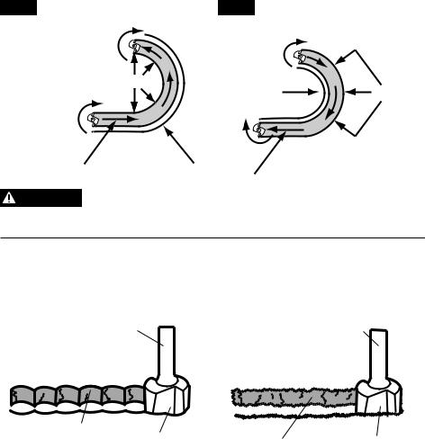
Rate of Feed (Figs.. 24a and 24b)
The proper rate of feed depends on several factors: the hardness and moisture content of the workpiece, the depth of cut, and the cutting diameter of the bit. When cutting shallow grooves in soft woods such as pine, you may use a faster rate of feed. When making deep cuts in hardwoods such as oak, you should use a slower rate of feed.
|
|
|
|
Fig. 24a |
Bit Shank |
Fig. 24b |
Bit Shank |
|
|
Cut |
Cutter |
Cut |
Cutter |
|
|||
TOO FAST |
|
|
TOO SLOW |
28
Feeding Too Fast (Fig.. 24a)
Clean and smooth cuts can only be achieved when the cutter bit is rotating at a relatively high speed, taking very small bites and producing tiny, clean cut chips.
Forcing the feed of the cutter bit forward too rapidly slows the rotation speed of the cutter bit, and the bit takes larger bites as it rotates. Bigger bites mean bigger chips and a rough finish. This forcing action can also cause the router motor to overheat.
Under extreme force-feeding conditions, the rotations can become so slow and the bites become so large that chips become partially cut off, causing splintering and gouging of the workpiece.
The router will make clean, smooth cuts if it is allowed to run freely without the overload of forced feeding. You can detect forced feeding by the sound of the motor. Its usual high-
pitched whine will sound lower and stronger as it loses speed. Holding the router against the workpiece will also come more difficult.
Feeding Too Slowly (Fig.. 24b)
When you feed the cutter bit too slowly, the rotating cutter bit does not cut into new wood rapidly enough to take a bite. Instead, it scrapes away sawdust-like particles. This scraping produces heat, which can glaze, burn, and mar the cut in the workpiece and, in extreme cases, overheat the cutter bit.
When the cutter bit is scraping instead of cutting, the router is more difficult to control as you feed it.
With the reduced load on the motor caused by the slow feed, the cutter bit has a tendency to bounce off the sides of the cut in the workpiece, producing a cut with a rippled finish instead of clean straight sides.
Chip Shield (Figs.. 25a and 25b)
|
Always wear eye protection. The chip shields are not intended as safety |
WARNING |
|
|
guards. |
|
To remove the chip shield from the fixed base, press inward on the tabs until the chip shield releases from base and then remove the chip shield. To attach, place the chip shield back in position and flex the sides while pushing in the shield until it snaps back into place (Fig. 25a).
The chip shield on the plunge base is held in position with a screw. To remove the chip shield from the plunge base, simply loosen the screw and take the chip shield off the base (Fig. 25b).
Fig. 25a |
Fig. 25b |
29
 WARNING
 CAUTION
The chip shield helps to keep dust and chips away from the operator; it will not stop objects larger than woodchips thrown from the bit.
Always have the appropriate chip shield in place on the base when operating the router.
|
Always turn the motor off and unplug the router from the power source |
WARNING |
|
|
before making any adjustments or installing accessories. Failure to turn |
|
the motor off and unplug router could result in accidental starting, which can cause serious personal injury.
Dust Collection with Vacuum Adapter
Two vacuum adapters are included with the router bases. Each adapter is sized to accept a 1-1/4-in. vac hose adapter.
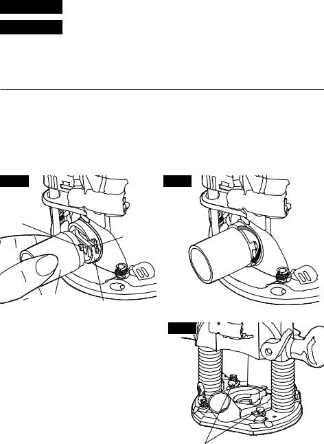
Attach the vacuum adapter onto the fixed base (Figs. 26a and 26b)
To attach the vacuum onto the vacuum port at back of the fixed base, first install the included vacuum adapter onto the vacuum port. Align the two tabs on the adapter with the two slots on the vacuum port, and secure it by turning it clockwise (Figs. 26a and 26b).
Fig. 26a |
Fig. 26b |
Tab
Slot
Vacuum |
Vacuum Port |
|
Adapter |
|
|
|
|
|
Attach the vacuum adapter onto the plunge |
Fig. 27 |
|
base (Fig..27) |
|
|
To attach the vacuum adapter onto the plunge base, position and secure it to the back of the base with the two thumb screws (included), as shown in Fig. 27.
Two Thumb Screws Included
30
 Loading...