


SM 2610948212 02-07 2/14/07 4:53 PM Page 1
!2610948212!
IMPORTANT: |
IMPORTANT : |
IMPORTANTE: |
Read Before Using |
Lire avant usage |
Leer antes de usar |
Operating/Safety Instructions 
 Consignes de fonctionnement/sécurité
Instrucciones de funcionamiento y seguridad
5550
Call Toll Free for |
Pour obtenir des informations |
Llame gratis para |
Consumer Information |
et les adresses de nos centres |
obtener información |
& Service Locations |
de service après-vente, |
para el consumidor y |
|
appelez ce numéro gratuit |
ubicaciones de servicio |
1-877-SKIL999 (1-877-754-5999) www.skil.com
For English Version |
Version française |
Versión en español |
See page 2 |
Voir page 13 |
Ver la página 24 |
SM 2610948212 02-07 2/14/07 4:53 PM Page 2
|
Power Tool Safety Rules |
|
Read and understand all instructions. Failure to follow all instructions listed |
! WARNING |
|
|
below, may result in electric shock, fire and/or serious personal injury. |
|
|
|
SAVE THESE INSTRUCTIONS |
Work Area
Keep your work area clean and well lit.
Cluttered benches and dark areas invite accidents.
Do not operate power tools in explosive atmospheres, such as in the presence of flammable liquids, gases, or dust. Power tools create sparks which may ignite the dust or fumes.
Keep by-standers, children, and visitors away while operating a power tool.
Distractions can cause you to lose control.
Electrical Safety
Double Insulated tools are equipped with a polarized plug (one blade is wider than the other.) This plug will fit in a polarized outlet only one way. If the plug does not fit fully in the outlet, reverse the plug. If it still does not fit, contact a qualified electrician to install a polarized outlet. Do not change the plug in any way. Double Insulation


 eliminates the need for the three wire grounded power cord and grounded power supply system. Before plugging in the tool, be certain the outlet voltage supplied is within the voltage marked on the nameplate. Do not use “AC only” rated tools with a DC power supply.
Avoid body contact with grounded surfaces such as pipes, radiators, ranges and refrigerators. There is an increased risk of electric shock if your body is grounded. If operating the power tool in damp locations is unavoidable, a Ground Fault Circuit Interrupter must be used to supply the power to your tool. Electrician’s rubber gloves and footwear will further enhance your personal safety.
Don't expose power tools to rain or wet conditions. Water entering a power tool will increase the risk of electric shock.
Do not abuse the cord. Never use the cord to carry the tools or pull the plug from an outlet. Keep cord away from heat, oil, sharp edges or moving parts. Replace damaged cords immediately. Damaged cords increase the risk of electric shock.
When operating a power tool outside, use an outdoor extension cord marked "W-A" or "W." These cords are rated for outdoor use and reduce the risk of electric shock. Refer to “Recommended sizes of Extension Cords” in the Accessory section of this manual.
Personal Safety
Stay alert, watch what you are doing and use common sense when operating a power tool. Do not use tool while tired or under the influence of drugs, alcohol, or medication. A moment of inattention while operating power tools may result in serious personal injury.
Dress properly. Do not wear loose clothing or jewelry. Contain long hair. Keep your hair, clothing, and gloves away from moving parts. Loose clothes, jewelry, or long hair can be caught in moving parts.
Keep handles dry, clean and free from oil and grease.
Avoid accidental starting. Be sure switch is “OFF” before plugging in. Carrying tools with your finger on the switch or plugging in tools that have the switch “ON” invites accidents.
Remove adjusting keys or wrenches before turning the tool “ON”. A wrench or a key that is left attached to a rotating part of the tool may result in personal injury.
Do not overreach. Keep proper footing and balance at all times. Proper footing and balance enables better control of the tool in unexpected situations.
Use safety equipment. Always wear eye protection. Dust mask, non-skid safety shoes, hard hat, or hearing protection must be used for appropriate conditions.
Tool Use and Care
Use clamps or other practical way to secure and support the workpiece to a stable platform. Holding the work by hand or against your body is unstable and may lead to loss of control.
-2-
SM 2610948212 02-07 2/14/07 4:53 PM Page 3
Do not force tool. Use the correct tool for your application. The correct tool will do the job better and safer at the rate for which it is designed.
Do not use tool if switch does not turn it “ON” or “OFF”. Any tool that cannot be controlled with the switch is dangerous and must be repaired.
Disconnect the plug from the power source before making any adjustments, changing accessories, or storing the tool. Such preventive safety measures reduce the risk of starting the tool accidentally.
Store idle tools out of reach of children and other untrained persons. Tools are dangerous in the hands of untrained users.
Maintain tools with care. Keep cutting tools sharp and clean. Properly maintained tools, with sharp cutting edges are less likely to bind and are easier to control. Any alteration or modification is a misuse and may result in a dangerous condition.
Check for misalignment or binding of moving parts, breakage of parts, and any other condition that may affect the tools
operation. If damaged, have the tool serviced before using. Many accidents are caused by poorly maintained tools. Develop a periodic maintenance schedule for your tool.
Use only accessories that are recommended by the manufacturer for your model. Accessories that may be suitable for one tool, may become hazardous when used on another tool.
Service
Tool service must be performed only by qualified repair personnel. Service or maintenance performed by unqualified personnel could result in a risk of injury. For example: internal wires may be misplaced or pinched, safety guard return springs may be improperly mounted.
When servicing a tool, use only identical replacement parts. Follow instructions in the Maintenance section of this manual.
Use of unauthorized parts or failure to follow Maintenance Instructions may create a risk of electric shock or injury. Certain cleaning agents such as gasoline, carbon tetrachloride, ammonia, etc. may damage plastic parts.
Safety Rules for Circular Saws
! DANGER Keep hands away from cutting area and blade. Keep
your second hand on auxiliary handle, or motor housing. If both hands are holding the saw, they cannot be cut by the blade. Hold the saw firmly to prevent loss of control. Figures in this manual illustrate typical hand support of the saw. NEVER place your hand behind the saw blade since kickback could cause the saw to jump backwards over your hand.
Keep your body positioned to either side of the saw blade, but not in line with the saw blade. KICKBACK could cause the saw to jump backwards. (See “Causes and Operator Prevention of Kickback.”)
Do not reach underneath the work. The guard cannot protect you from the blade below the work. Do not attempt to remove cut material when blade is moving.
Check lower guard for proper closing before each use. Do not operate saw if lower guard does not move freely and close instantly. Never clamp or tie the lower guard into the
open position. If saw is accidentally dropped, lower guard may be bent. Raise the lower guard only with the Lower Guard Lift Lever and make sure it moves freely and does not touch the blade or any other part, in all angles and depths of cut.
Check the operation of the lower guard spring. If the guard and the spring are not operating properly, they must be serviced before use. Lower guard may operate sluggishly due to damaged parts, gummy deposits, or a buildup of debris. Disconnect the plug from power source. Periodically remove the blade, clean the upper, lower guards and the hub area with kerosene and wipe it dry, or blow it clean with compressed air.
Lower guard should be retracted manually only for special cuts such as “Pocket Cuts” and “Compound Cuts”. Raise lower guard by Lower Guard Lift Lever. As soon as blade enters the material, lower guard must be released. For all other sawing, the lower guard should operate automatically.
-3-
SM 2610948212 02-07 2/14/07 4:53 PM Page 4
Always observe that the lower guard is covering the blade before placing saw down on bench or floor. An unprotected, coasting blade will cause the saw to walk backwards, cutting whatever is in its path. Be aware of the time it takes for the blade to stop after switch is released.
NEVER hold piece being cut in your hands or across your leg. It is important to support the work properly to minimize body exposure, blade binding, or loss of control.
Hold tool by the insulated gripping surfaces when performing an operation where the cutting tool may contact hidden wiring or it own cord. Contact with a "live" wire will also make exposed metal parts of the tool “live” and shock the operator.
When ripping always use a rip fence or straight edge guide. This improves accuracy of cut and reduces the chance for blade binding.
Always use blades with correct size and shape (diamond vs. round) arbor holes.
Blades that do not match the mounting hardware of the saw will run eccentrically, causing loss of control and will not allow proper vari-torque engagement.
Never use damaged or incorrect blade washers or bolts. The blade washers and bolt were specially designed for your saw, for optimum performance and safety of operation.
The blade washers and the bolt on your saw have been designed to work as a “VARITORQUE CLUTCH”. Understand the operation and settings of the VARI-TORQUE CLUTCH, because the proper setting of the CLUTCH, combined with firm handling of the saw will allow you to control KICKBACK.
Do not run the saw while carrying it at your side. Lower guard may be opened by a contact with your clothing. Accidental contact with the spinning saw blade could result in serious personal injury.
Depending upon use, the switch may not last the life of the saw. If the switch should fail in the “OFF” position, the saw may not start. If it should fail while the saw is running, the saw may not shut off. If either occurs, unplug the saw immediately and do not use until repaired.
This circular saw should not be mounted to a table and converted to a table saw. Circular saws are not designed or intended to be used as table saws.
CAUSES AND OPERATOR PREVENTION
OF KICKBACK:
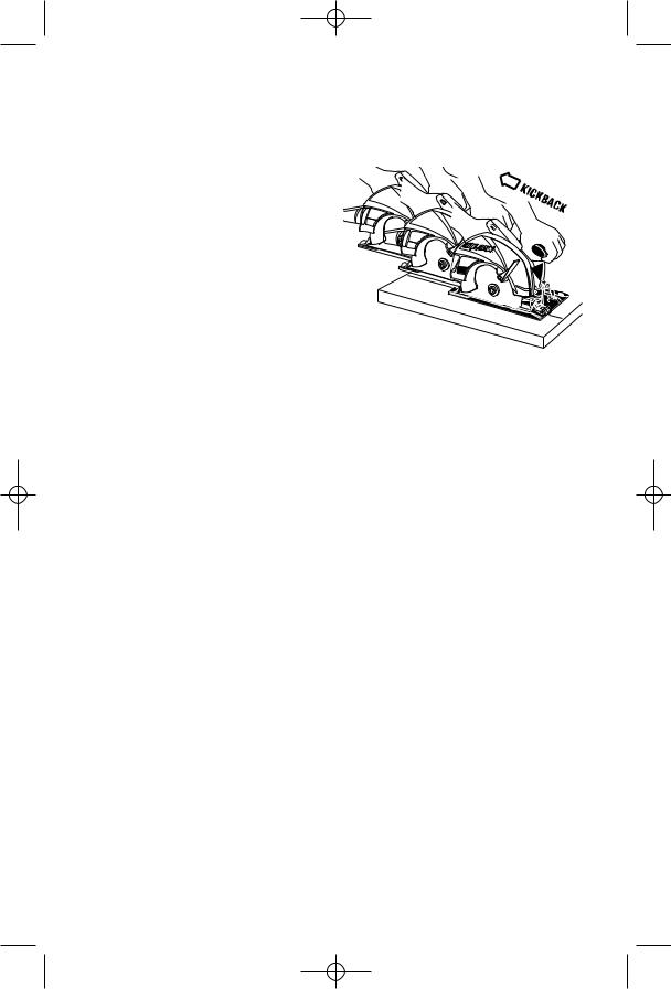
Kickback is a sudden reaction to a pinched, bound or misaligned saw blade, causing an uncontrolled saw to lift up and out of the workpiece toward the operator.
When the blade is pinched or bound tightly by the kerf closing down, the blade stalls and the motor reaction drives the unit rapidly back toward the operator.
If the blade becomes twisted or misaligned in the cut, the teeth at the back edge of the blade can dig into the top surface of the wood causing the blade to climb out of the kerf and jump back toward the operator.
Kickback is the result of tool misuse and/or incorrect operating procedures or conditions and can be avoided by taking proper precautions as given below:
Maintain a firm grip with both hands on the saw and position your body and arm to allow you to resist KICKBACK forces.
KICKBACK forces can be controlled by the operator, if proper precautions are taken.
When blade is binding, or when interrupting a cut for any reason, release the trigger and hold the saw motionless in the material until the blade comes to a complete stop. Never attempt to remove the saw from the work or pull the saw backward while the blade is in motion or KICKBACK may occur. Investigate and take corrective action to eliminate the cause of blade binding. Wet lumber, green lumber or pressure treated lumber require special attention during cutting operation to prevent KICKBACK. Avoid cutting nails. Inspect for and remove all nails from lumber before cutting.
When restarting a saw in a workpiece, center the saw blade in the kerf and check that saw teeth are not engaged into the material. If saw blade is binding, it may walk up
-4-
SM 2610948212 02-07 2/14/07 4:53 PM Page 5
or KICKBACK from the workpiece as the saw is restarted.
Support large panels to minimize the risk of blade pinching and KICKBACK. Large panels tend to sag under their own weight. Supports must be placed under the panel on both sides, near the line of cut and near the edge of the panel. See “Cutting Large Sheets” in this manual.
Do not use dull or damaged blade.
Unsharpened or improperly set blades produce narrow kerf causing excessive friction, blade binding and KICKBACK.
Blade depth and bevel adjusting locking knobs must be tight and secure before making cut. If blade adjustment shifts while cutting, it may cause binding and KICKBACK.
Using the saw with an excessive depth of cut setting increases loading on the unit and susceptibility to twisting of the blade in the kerf. It also increases the surface area of the blade available for pinching under conditions of kerf close down.
Use extra caution when making a “Pocket Cut” into existing walls or other blind areas.
The protruding blade may cut objects that can cause KICKBACK.
Some dust created by ! WARNING power sanding, sawing,
grinding, drilling, and other construction activities contains chemicals known to cause cancer, birth defects or other reproductive harm. Some examples of these chemicals are:
•Lead from lead-based paints,
•Crystalline silica from bricks and cement and other masonry products, and
•Arsenic and chromium from chemicallytreated lumber.
Your risk from these exposures varies, depending on how often you do this type of work. To reduce your exposure to these chemicals: work in a well ventilated area, and work with approved safety equipment, such as those dust masks that are specially designed to filter out microscopic particles.
-5-

SM 2610948212 02-07 2/14/07 4:53 PM Page 6
Symbols
IMPORTANT: Some of the following symbols may be used on your tool. Please study them and learn their meaning. Proper interpretation of these symbols will allow you to operate the tool better and safer.
Symbol |
Name |
Designation/Explanation |
|||||
|
|
V |
Volts |
Voltage (potential) |
|||
|
|
A |
Amperes |
Current |
|||
|
|
Hz |
Hertz |
Frequency (cycles per second) |
|||
|
|
W |
Watt |
Power |
|||
|
|
kg |
Kilograms |
Weight |
|||
|
min |
Minutes |
Time |
||||
|
|
s |
Seconds |
Time |
|||
|
|
|
|
|
|
Diameter |
Size of drill bits, grinding wheels, etc. |
|
|
n0 |
No load speed |
Rotational speed, at no load |
|||
.../min |
Revolutions or reciprocation per minute |
Revolutions, strokes, surface speed, |
|||||
|
|
|
|
|
|
|
orbits etc. per minute |
0 |
|
|
|
Off position |
Zero speed, zero torque... |
||
1, 2, 3, ... |
Selector settings |
Speed, torque or position settings. |
|||||
I, II, III, |
|
Higher number means greater speed |
|||||
0 |
|
|
|
|
Infinitely variable selector with off |
Speed is increasing from 0 setting |
|
|
|
|
|
|
|
Arrow |
Action in the direction of arrow |
|
|
|
|
|
|
||
|
|
|
|
|
|
||
|
|
|
|
|
|
Alternating current |
Type or a characteristic of current |
|
|
|
|
|
|
Direct current |
Type or a characteristic of current |
|
|
|
|
|
|
||
|
|
|
|
|
|
Alternating or direct current |
Type or a characteristic of current |
|
|
|
|
|
|
||
|
|
|
|
|
|
Class II construction |
Designates Double Insulated |
|
|
|
|
|
|
||
|
|
|
|
|
|
|
Construction tools. |
|
|
|
|
|
|
|
|
|
|
|
|
|
|
Earthing terminal |
Grounding terminal |
|
|
|
|
|
|
||
|
|
|
|
|
|
Warning symbol |
Alerts user to warning messages |
|
|
|
|
|
|
||
|
|
|
|
|
|
||
|
|
|
|
|
|
Ni-Cad RBRC seal |
Designates Ni-Cad battery recycling |
|
|
|
|
|
|
|
program |
|
|
|
|
|
|
|
|
This symbol designates that this tool is listed by Underwriters Laboratories.
This symbol designates that this tool is listed by the Canadian Standards Association.
This symbol designates that this tool is listed to Canadian Standards by Underwriters Laboratories.
This symbol designates that this tool is listed by Underwriters Laboratories, and listed to Canadian Standards by Underwriters Laboratories.
This symbol designates that
this tool complies to NOM Mexican Standards.
-6-

SM 2610948212 02-07 2/14/07 4:53 PM Page 7
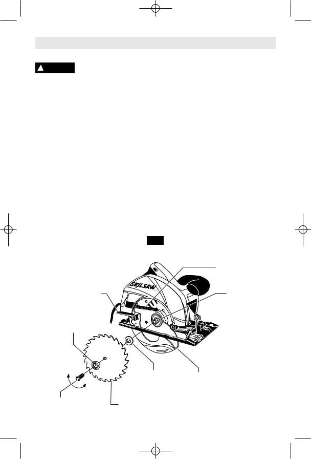
Functional Description and Specifications
! WARNING Disconnect the plug from the power source before making any assembly, adjustments or changing accessories. Such preventive safety
measures reduce the risk of starting the tool accidentally.
Circular Saw
FIG. 1
SAFETY SWITCH
UPPER AUXILIARY
GUARD HANDLE
|
CALIBRATED |
|
LOWER |
BEVEL |
|
QUADRANT |
||
GUARD LIFT |
||
|
||
LEVER |
BEVEL |
|
|
||
|
ADJUSTMENT |
|
|
KNOB |
ADJUSTABLE LINE
GUIDE
LOWER
GUARD FOOT
DEPTH
SCALE
|
|
DEPTH ADJUSTMENT |
|
|
|
LEVER |
|
|
|
BLADE WRENCH & |
|
|
|
STORAGE AREA |
|
Maximum Capacities |
|
|
|
Blade |
7-1/4" |
Depth of cut at 90° |
2-7/16" |
Blade arbor hole |
Round |
Depth of cut at 45° |
1-15/16" |
NOTE: For tool specifications refer to the nameplate on your tool.
-7-
SM 2610948212 02-07 2/14/07 4:53 PM Page 8
Assembly
ATTACHING THE BLADE
Disconnect the plug from ! WARNING the power source before
making any assembly, adjustments or changing accessories. Such preventive safety measures reduce the risk of starting the tool accidentally.
1.Turn BLADE STUD with wrench provided counter-clockwise and remove BLADE STUD and OUTER WASHER (Fig. 2). If the shaft moves while attempting to loosen the blade stud, strike the wrench counter-clockwise to jar BLADE STUD loose.
2.Retract the lower guard all the way up into the upper guard. While retracting the lower guard, check operation and condition of the LOWER GUARD SPRING.
3.Make sure the saw teeth and arrow on the blade point in the same direction as the arrow on the lower guard.
4.Slide blade through slot in the foot and mount it against the INNER WASHER on the shaft. Be sure the large diameter of the OUTER washer lays flush against the blade.
5.Reinstall OUTER WASHER and tighten BLADE STUD finger tight. To lock shaft hold
the saw securely by the upper guard with blade teeth imbedded in scrap wood and TIGHTEN BLADE STUD 1/8 TURN (45°) WITH THE WRENCH PROVIDED.
Do not use wrenches with longer handles, since it may lead to over tightening of the blade stud.
VARI-TORQUE CLUTCH
This clutching action is provided by the friction of the OUTER WASHER against the BLADE and permits the blade shaft to turn when the blade encounters excessive resistance. When the BLADE STUD is properly tightened (as described in No. 5 of Attaching The Blade), the blade will slip when it encounters excessive resistance, thus reducing saw’s tendency to KICKBACK.
One setting may not be sufficient for cutting all materials. If excessive blade slippage occurs, tighten the blade stud a fraction of a turn more (less than 1/8 turn). OVERTIGHTENING THE BLADE STUD NULLIFIES THE EFFECTIVENESS OF THE CLUTCH.
FIG. 2
LOWER GUARD
SPRING
LOWER GUARD |
BLADE SHAFT |
LIFT LEVER |
|
OUTER WASHER
Large Diameter
Faces Blade
Tighten |
INNER WASHER |
LOWER |
|
||
|
Large Diameter |
GUARD |
|
Faces Blade |
|
|
Loosen |
|
BLADE |
BLADE |
|
STUD |
|
|
|
|
-8-

SM 2610948212 02-07 2/14/07 4:53 PM Page 9
Operating Instructions
DEPTH ADJUSTMENT
Disconnect plug from power source. Loosen desired. Check desired depth (Fig. 3). the depth adjustment lever located between
the guard and handle of saw. Hold the foot down with one hand and raise or lower saw by the handle. Tighten lever at the depth setting
FIG. 3 |
DEPTH |
|
SCALE |
DEPTH
ADJUSTMENT
LEVER
BLADE WRENCH,
& STORAGE
AREA
SAFETY SWITCH
The safety switch is designed to prevent accidental starts. To operate safety switch, press the release button with your thumb on either side of handle to disengage the lock, then pull the trigger (Fig. 5). When the trigger is released the button will engage the safety switch automatically, and the trigger will no longer operate. (See Switch & General Cuts on page 10.)
FIG. 5 |
SAFETY SWITCH |
FIG. 6 |
FIG. 7 |
|
RELEASE |
|
|
|
BUTTON |
|
|
TRIGGER
FOOT
BLADE |
90º |
BEVEL |
TAB |
ADJUSTMENT |
|
||
|
|
||
|
|
KNOB |
|
BEVEL ADJUSTMENT |
FIG. 8 |
Disconnect plug from power source. The foot can be adjusted up to 45° by loosening the bevel adjustment knob at the front of the saw. Align to desired angle on calibrated quadrant. Then tighten bevel adjustment knob (Fig. 8). Because of the increased amount of blade engagement in the work and decreased stability of the foot, blade binding may occur. Keep the saw steady and the foot firmly on the workpiece.
QUADRANT
BEVEL
ADJUSTMENT

 KNOB
KNOB
-9-
SM 2610948212 02-07 2/14/07 4:53 PM Page 10
ADJUSTABLE LINE GUIDE
For a straight 90° cut you can use the left or right side of notch in the foot. For 45° bevel cuts, use the left side (Fig 9). The guide can be adjusted to allow for variation in blade thicknesses for whichever side of the blade the user would prefer to cut the line on.
TO ATTACH: Disconnect plug from power source. Align hole in adjustable line guide with hole in foot and secure with screw provide.
TO ADJUST: Loosen but don’t remove, the adjustment screw enough so the guide can move freely. Set a straightedge flat on the preferred side of the blade, lining up both the
edge of the straightedge and the edge of the guide where the 0° mark is located.
FIG. 9 |
45° |
90° |
BEVEL CUTS |
VERTICAL |
|
|
|
CUTS |
ADJUSTABLE |
LINE GUIDE |
GUIDE
ADJUSTMENT
SCREW
SWITCH
! WARNING When starting the tool, hold it with both hands. The
torque from the motor can cause the tool to twist.
To turn tool “ON”, squeeze the trigger switch. To turn the tool “OFF”, release the trigger switch, which is spring loaded and will return to the off position automatically.
Your saw should be running at full speed BEFORE starting the cut, and turned off only AFTER completing the cut. To increase switch life, do not turn switch on and off while cutting.
GENERAL CUTS
Always hold the saw handle with one hand and the auxiliary handle or housing with the other.
! WARNING Always be sure either hand does not interfere with the
free movement of the lower guard.
Maintain a firm grip and operate the switch with a decisive action. Never force the saw. Use light and continuous pressure.
! WARNING After completing a cut and the trigger has been
released, be aware of the necessary time it takes for the blade to come to a complete stop during coast down. Do not allow the saw to brush against your leg or side, since the lower guard is retractable, it could catch on your clothing and expose the blade. Be aware of the necessary blade exposures that exist in both the upper and lower guard areas.
When cutting is interrupted, to resume cutting: squeeze the trigger and allow the blade to reach full speed, re-enter the cut slowly and resume cutting.
When cutting across the grain, the fibers of the wood have a tendency to tear and lift. Advancing the saw slowly minimizes this effect. For a finished cut, a cross cut blade or miter blade is recommended.
CUTTING MASONRY/METAL
This tool is not recommended for continuous and general usage with metal or masonry cutoff wheels. If you use your saw for cutting these materials, use the appropriate wheel for the material being cut.
When cutting masonry, do not cut a depth of more than 1/4 inch (6 mm). Make successive passes to achieve desired depth. Apply a light forward pressure. Do not overload motor. Disconnect plug from power source and clean dust from air vents frequently. Metal cutting is done at full depth.
! WARNING Clean guards frequently to assure a rapid return of
lower guard. The lower guard may become sluggish when cutting masonry materials.
! WARNING Abrasive Cut Off Wheels must have a maximum safe
operating speed greater than the “no load RPM” marked on the tool’s nameplate.
Wheels running over the rated speed can fly apart and cause injury.
! WARNING |
Do not use the abrasive cut |
|
off wheel near flammable |
materials. Sparks from the wheel could ignite these materials.
! WARNING This machine is not intended to be used with
Wet Diamond Wheels. Using water or other liquid coolants with this machine may result in electrocution or shock. Use of Dry Diamond Wheels is acceptable.
-10-
SM 2610948212 02-07 2/14/07 4:53 PM Page 11
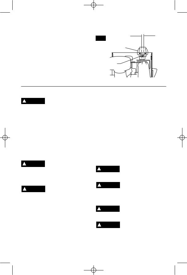
POCKET CUTS
Disconnect the plug from the power source before making adjustments. Set depth adjustment according to material to be cut. Tilt saw forward with cutting guide notch lined up with the line you’ve drawn. Raise the lower guard, using lift lever and hold the saw by the front and rear handles (Fig. 10).
With the blade just clearing the material to be cut, start the motor. Gradually lower the back end of saw using the front end of the foot as the hinge point. WARNING: As blade starts cutting the material, release the lower guard immediately. When the foot rests flat on the surface being cut, proceed cutting in forward direction to end of cut. WARNING: Allow blade to come to a complete stop before lifting the saw from cut. Also, never pull the saw backward since blade will climb out of the material and KICKBACK will occur. Turn saw around and finish the cut in the normal manner, sawing forward. If corners of your pocket cut are not completely cut through, use a jigsaw or hand saw to finish the corners.
FIG. 10 |
LOWER |
|
GUARD |
|
LIFT |
FOOT |
LEVER |
|


 LINE
LINE
GUIDE
CUTTING LARGE SHEETS
Large sheets and long boards sag or bend, depending on support. If you attempt to cut without leveling and properly supporting the piece, the blade will tend to bind, causing KICKBACK and extra load on the motor (Fig. 11).
Support the panel or board close to the cut, as shown in (Fig. 12). Be sure to set the depth of the cut so that you cut through the sheet or board only and not the table or work bench. The two-by-fours used to raise and support the work should be positioned so that the broadest sides support the work and rest on the table or bench. Do not support the work with the narrow sides as this is an unsteady arrangement. If the sheet or board to be cut is too large for a table or work bench, use the supporting two-by-fours on the floor and secure.
FIG. 11
WRONG
FIG. 12
RIGHT
RIP CUTS
The combination blade provided with your saw is for both cross cuts and rip cuts. Ripping is cutting lengthwise with the grain of the wood. Rip cuts are easy to do with a rip fence (Fig. 13). Rip Fence is available as an accessory (not included). To attach fence, insert fence through slots in foot to desired width as shown and secure with the wing nut (not included).
FIG. 13
WING
NUT
DESIRED
WIDTH
OF CUT
RIP FENCE
RIP BOARD GUIDE
When rip cutting large sheets, the rip fence may not allow the desired width of cut. Clamp or nail a straight piece of 1" lumber to the sheet as a guide (Fig. 14). Use the right side of the foot against the board guide.
FIG. 14
RIP
BOARD
GUIDE
DESIRED LINE
OF CUT
-11-
 Loading...