


Orthophos XG3
Table of contents
 Loading...
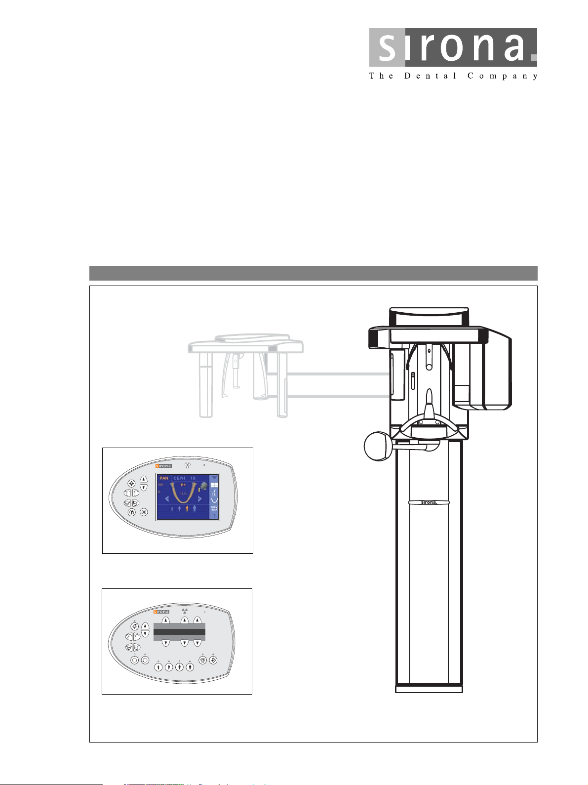
loqelmelp=ud=Pa
Easypad
T
R
Prog.
S
kV
mA
P1
Multipad
êÉ~Çó
=L=`ÉéÜ
loqelmelp=ud
=ap=L=`ÉéÜ
loqelmelp=ud=R=EapF=L=`ÉéÜ
loqelmelp=ud=P=EapF
pЙкобЕЙ=j~ем~д
mäìë
bеЦдблЬ
ORTHOPHOS XG 3D
ORTHOPHOS XG 5 / 3 / 3 PPE
sЙклбзе=OSKM
ready
/ XG
Plus

About the Service Manual:
NOTE
i
NOTE
i
• This Service Manual is valid for the following unit versions:
– ORTHOPHOS XG 3D
– ORTHOPHOS XG
– ORTHOPHOS XG 5 DS / Ceph
– ORTHOPHOS PlusDS/PlusDSCeph / PPE*
– ORTHOPHOS XG 5 / Ceph
– ORTHOPHOS XG 3
These system versions differ regarding the equipment offered by their user interfaces and their possible configuration levels (see page 1-4).
Board DX41 is no longer installed in units with hardware version BA or higher (as of November 2006).
In addition, you also require:
• Spare parts list: Order No. 59 38 423
– ORTHOPHOS XG 3D
ORTHOPHOS XG 5 (DS) / Ceph,
ORTHOPHOS XG 3 (DS)
ready
Plus
DS / Ceph
ready
/ Ceph
/ Ceph, ORTHOPHOS XG
Plus
DS / Ceph,
• Wiring diagrams: Order No. 59 38 332
– ORTHOPHOS XG
Plus
DS / Ceph, ORTHOPHOS XG 5 (DS) / Ceph,
ORTHOPHOS XG 3 (DS): Bestell-Nr. 59 38 332
– ORTHOPHOS XG 3D
ready
/ Ceph: Bestell-Nr. 63 03 494
• Installation Instructions
– ORTHOPHOS XG
Plus
DS / Ceph, ORTHOPHOS XG 3D
– ORTHOPHOS XG 5 (DS) / Ceph: Order No. 60 04 902
– ORTHOPHOS XG 3 (DS): Order No. 60 51 416
• Tools
– Screwdriver, medium sized
– Torx offset screwdrivers TX10, TX20, TX25
– Open-end wrench, 13 mm A/F
– Socket wrench, 13 mm A/F
– Side cutters
– Spirit level
• Auxiliary devices
– Digital multimeter, Accuracy Class 1
– Mult-O-Meter 512L
– Soldering tool for repairing cables
– Cable ties
– Teflon tape
– Loctite
ready
/ Ceph: Order No. 59 87 651
*PPE = pay per exposure (optional)
General information/Software update 1
Messages
Troubleshooting
Adjustment
2
3
4
Service routines 5
Repair
Maintenance
6
7


Contents
1 General information ..................................................................... 1-5
1.1 Safety .................................................................................. 1-5
1.2 Device classes XG
1.3 Operation notes ................................................................... 1-8
1.4 Demo mode – Operation without radiation release ........... 1-11
1.5 Demo mode – Repacking andtransport ............................ 1-13
1.6 List of software versions .................................................... 1-14
1.7 Software update ................................................................ 1-27
1.8 Opening the "Details" ........................................................ 1-37
1.9 Configuring X-ray components via the SIDEXIS Manager 1-39
1.10 The most important modules and components ................. 1-45
1.11 Cabling overview ............................................................... 1-50
1.12 Illustrations of boards ........................................................ 1-54
1.13 Remove covers ................................................................. 1-66
Plus
/ 3D
ready
and XG 5 / 3 / 3 PPE ....... 1-6
2 Messages .................................................................................... 2-3
2.1 Help messages ................................................................... 2-4
2.2 System messages ............................................................... 2-6
2.3 Status displays .................................................................... 2-6
2.4 Error messages ................................................................... 2-6
2.5 List of error messages ......................................................... 2-9
2.6 List of available service routines ....................................... 2-59
3 Troubleshooting .......................................................................... 3-3
3.1 Error logging memory .......................................................... 3-4
3.2 Check the CAN bus ............................................................. 3-6
3.3 Checking the boards ......................................................... 3-12
3.4 Checking the motors ......................................................... 3-15
3.5 Checking the light barriers ................................................ 3-16
3.6 Device leakage current too high ........................................ 3-17
3.7 Checking the cables .......................................................... 3-18
3.8 Error analysis of X-RAY control signal path:
up to unit hardware version AG
(with board DX41) ............................................................. 3-19
3.9 Error analysis of X-RAY control signal path:
unit HW version BA or higher
(without board DX41) ........................................................ 3-23
3.10 Checking data paths / Generating test images ................. 3-26
59 38 399 D3352
D3352.076.01.26.02 09.2016
V

Contents
4 Adjustment ................................................................................... 4-3
4.1 Important information concerning adjustment ...................... 4-3
4.2 Diaphragm/system adjustment menu .................................. 4-5
4.3 Adjusting the panoramic X-ray unit ...................................... 4-9
4.4 Checking and adjusting the touchscreen
(only for XG
4.5 Adjusting the cephalometer
(XG
Plus
4.6 TSA sensor adjustment
(only for XG
4.7 Resetting the adjustment
(XG
Plus
/ 3D
/ 3D
Plus
ready
Plus
ready
ready
/ 3D
) .................................................. 4-55
/ XG 5, if ceph present) .......................... 4-58
with full version) ..................................... 4-109
/ 5 / 3 / 3 PPE) ...................................... 4-117
5 Service routines ......................................................................... 5-11
5.1 Selecting the Service menu ............................................... 5-12
5.2 Selecting a service routine ................................................. 5-17
5.3 Service routines with SIDEXIS .......................................... 5-20
5.4 Service routine S001 ......................................................... 5-23
5.5 Service routine S002 ......................................................... 5-25
5.6 Service routine S005 ......................................................... 5-30
5.7 Service routine S007 ......................................................... 5-44
5.8 Service routine S008 ......................................................... 5-53
5.9 Service routine S009 ......................................................... 5-61
5.10 Service routine S012 ......................................................... 5-64
5.11 Service routine S014 ......................................................... 5-74
5.12 Service routine S015 ......................................................... 5-81
5.13 Service routine S017 ......................................................... 5-84
5.14 Service routine S018 ....................................................... 5-121
5.15 Service routine S020 (not for XG 3 / 3 PPE) ................... 5-139
5.16 Service routine S021 (not for XG 3 / 3 PPE) ................... 5-143
5.17 Service routine S032 ....................................................... 5-148
5.18 Service routine S033 (not for XG 3 / 3 PPE) ................... 5-152
5.19 Service routine S034 ....................................................... 5-156
5.20 Service routine S037 ....................................................... 5-173
59 38 399 D3352
VI D3352.076.01.26.02 09.2016

Contents
6 Repair .......................................................................................... 6-5
6.1 Safety check ........................................................................ 6-6
6.2 Replacing the height adjustment motor (M1_4)/spindle ...... 6-7
6.3 Replacing the ring motor (M1_3) ....................................... 6-19
6.4 Replacing the PAN actuators (M1_1/2) ............................. 6-22
6.5 Replace headrest .............................................................. 6-24
6.6 Easypad (XG
Plus
Or the Multipad for XG5 / 3 / 3 PPE) ................................. 6-26
6.7 Replacing the control panel ............................................... 6-29
6.8 Replacing/adjusting the FH light localizer (PAN) .............. 6-31
6.9 Replacing/adjusting the MS light localizer
laser module (PAN) ........................................................... 6-33
6.10 Replacing/adjusting the FH light localizer (Ceph) ............. 6-35
6.11 Removing the light localizers from the ring
(for XG
Plus
and XG 5, if present) ....................................... 6-37
6.12 Replacing the bite block holder ......................................... 6-38
6.13 Replacing the motor-driven diaphragm
(for XG
Plus
/ 3D
6.14 Replacing the fixed diagram (for XG 3 / 3 PPE) ................ 6-45
6.15 Replacing the X-ray tube assembly .................................. 6-48
6.16 Replacing the fan (tube assembly 1.0) .............................. 6-53
6.17 Replacing the fan (tube assembly 2.0) .............................. 6-54
6.18 Replacing the PAN (TSA) sensor holder ........................... 6-56
6.19 Replacing the ceph sensor holder ..................................... 6-60
6.20 Replace sensor ................................................................. 6-61
6.21 Replacing the light barriers ............................................... 6-62
6.22 Replacing circuit boards .................................................... 6-73
6.23 Replacing cables ............................................................. 6-101
ready
/ 3D
ready
) or
/ XG 5) .............................................. 6-41
59 38 399 D3352
D3352.076.01.26.02 09.2016
VII

Contents
7 Maintenance ................................................................................ 7-3
7.1 Checking the height adjustment .......................................... 7-4
7.2 Checking the forehead and temple supports ....................... 7-6
7.3 Testing the rotating unit for smooth running ........................ 7-7
7.4 Checking the sensor holder (pan and ceph) ........................ 7-8
7.5 Checking the bite block holder ........................................... 7-10
7.6 Checking the light localizers .............................................. 7-11
7.7 Checking the X-ray images ................................................ 7-13
7.8 Checking the tube data ...................................................... 7-14
7.9 Checking the diaphragm .................................................... 7-20
7.10 Checking the cables for damage ....................................... 7-38
7.11 Checking the idling rollers .................................................. 7-39
7.12 Checking the grounding straps .......................................... 7-40
7.13 Checking the cable shields ................................................ 7-41
7.14 Checking the protective ground wires ................................ 7-42
7.15 Checking the unit leakage current ..................................... 7-46
59 38 399 D3352
VIII D3352.076.01.26.02 09.2016

ORTHOPHOS XG
1General information

Tab 1
Contents
1.1 Safety ......................................................................1 – 5
1.2 Device classes XG
Plus
XG 5 / 3 / 3 PPE......................................................1 – 6
1.2.1 Overview of the ORTHOPHOS XG
system classes and versions1 – 7
1.3 Operation notes.......................................................1 – 8
1.4 Demo mode – Operation without radiation release1 – 11
1.4.1 Switching the demo mode ON............................ 1 – 12
1.4.2 Switching the demo mode OFF.......................... 1 – 12
1.5 Demo mode – Repacking and transport ...............1 – 13
1.6 List of software versions........................................1 – 14
1.6.1 ORTHOPHOS XG 3 PPE ................................... 1 – 14
1.6.2 ORTHOPHOS XG 3 ........................................... 1 – 17
1.6.3 ORTHOPHOS XG 5 / Ceph ............................... 1 – 20
1.6.4 ORTHOPHOS XG
1.6.5 ORTHOPHOS XG 3D
ready
/ 3D
Plus
/ Ceph............................. 1 – 23
ready
and
/Ceph ....................... 1 – 26
1.7 Software update .................................................... 1 – 27
1.7.1 Important information on the software update.... 1 – 27
1.7.2 Performing a software update ............................ 1 – 29
1.7.3 Software update of ORTHOPHOS XG 5 to
V02.30 or higher ................................................. 1 – 34
1.7.4 Software update ORTHOPHOS XG
from version V02.20 to V02.30 or higher............ 1 – 35
1.7.5 Software update of ORTHOPHOS XG
version V02.22 to V02.30 or higher.................... 1 – 36
Plus
Plus
from
1.8 Opening the "Details" ............................................1 – 37
1.9 Configuring X-ray components via the
SIDEXIS Manager.................................................1 – 39
1.9.1 Setting up the X-ray component......................... 1 – 39
1.9.2 Selecting an X-ray component ........................... 1 – 40
1.9.3 Approval of the X-ray component....................... 1 – 43
1.9.4 Deleting the X-ray component............................ 1 – 44
1.10 The most important modules and components .....1 – 45
1.10.1 Slide ................................................................... 1 – 46
1.10.2 Stand .................................................................. 1 – 48
1.10.3 Cephalometer
(arm mounted on left side and on right side) ...... 1 – 49
1.10.4 Remote control ................................................... 1 – 49
1.11 Cabling overview................................................... 1 – 50
59 38 399 D3352
1 – 2 D3352.076.01.26.02 09.2016

Tab 1
1.12 Illustrations of boards ............................................1 – 54
1.12.1 Boards in the slide.............................................. 1 – 54
1.12.2 Boards in the stand ............................................ 1 – 62
1.12.3 Boards in the cephalometer
(arm mounted on left side and on right side)...... 1 – 63
1.12.4 Boards in the remote control .............................. 1 – 64
1.13 Remove covers .....................................................1 – 66
59 38 399 D3352
D3352.076.01.26.02 09.2016
1 – 3

Tab 1
59 38 399 D3352
1 – 4 D3352.076.01.26.02 09.2016
1.1
Tab 1 1.1 Safety
CAUTION
WARNING
DANGER
1 General information
1.1 Safety
Repair work is only to be performed by trained dealers / service engineers who are authorized by Sirona. The Service Manual is provided
purely for these persons.
It is essential that you comply with the warning and safety information contained in this Service Manual.
All such information is highlighted by one of three signal words, i.e. WARNING, CAUTION or DANGER.
Nonobservance may result in minor physical injuries or material damage and
malfunctions.
Nonobservance may lead to serious physical injury or death.
Immediate danger to life and limb. Threat of serious physical injury or
death.
1.1
bеЦдблЬ
59 38 399 D3352
D3352.076.01.26.02 09.2016
1 – 5
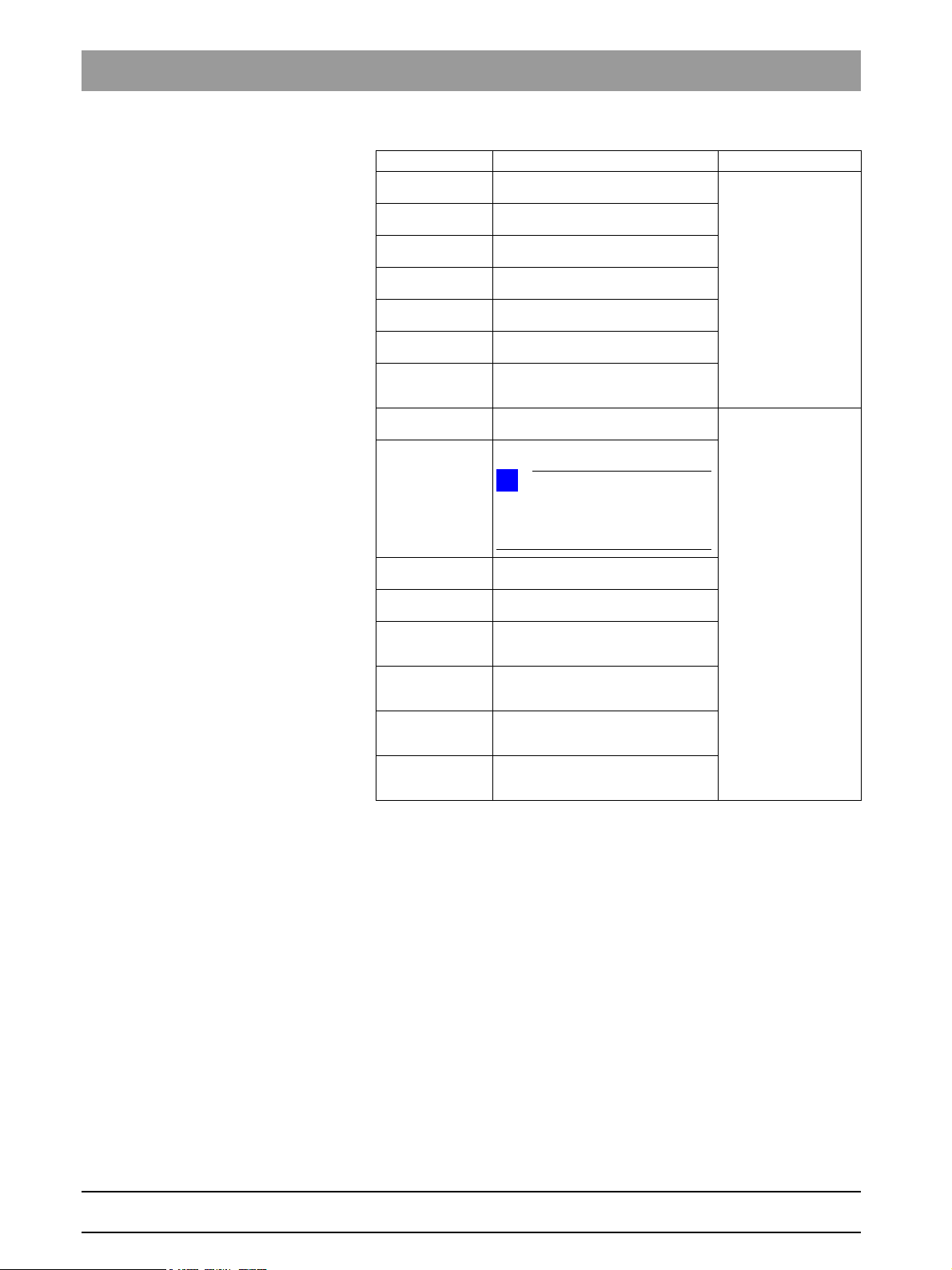
1.2 Device classes XG
NOTE
i
NOTE
i
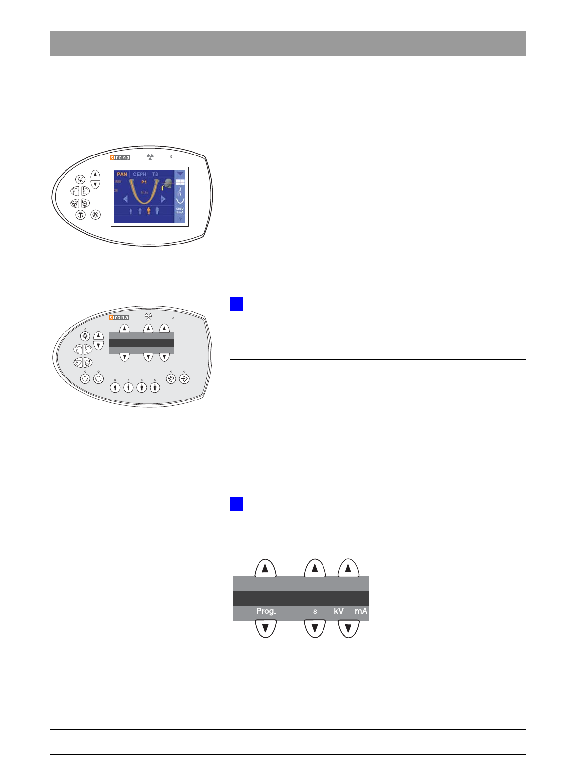
Comfort class with Easypad
(XG
Plus
/ 3D
ready
)
Basic class with Multipad
(XG 5 / 3 / 3 PPE)
T
R
Prog.
S
kV
mA
123
S005_______1____
Plus
/ 3D
ready
and XG 5 / 3 / 3 PPE Tab 1
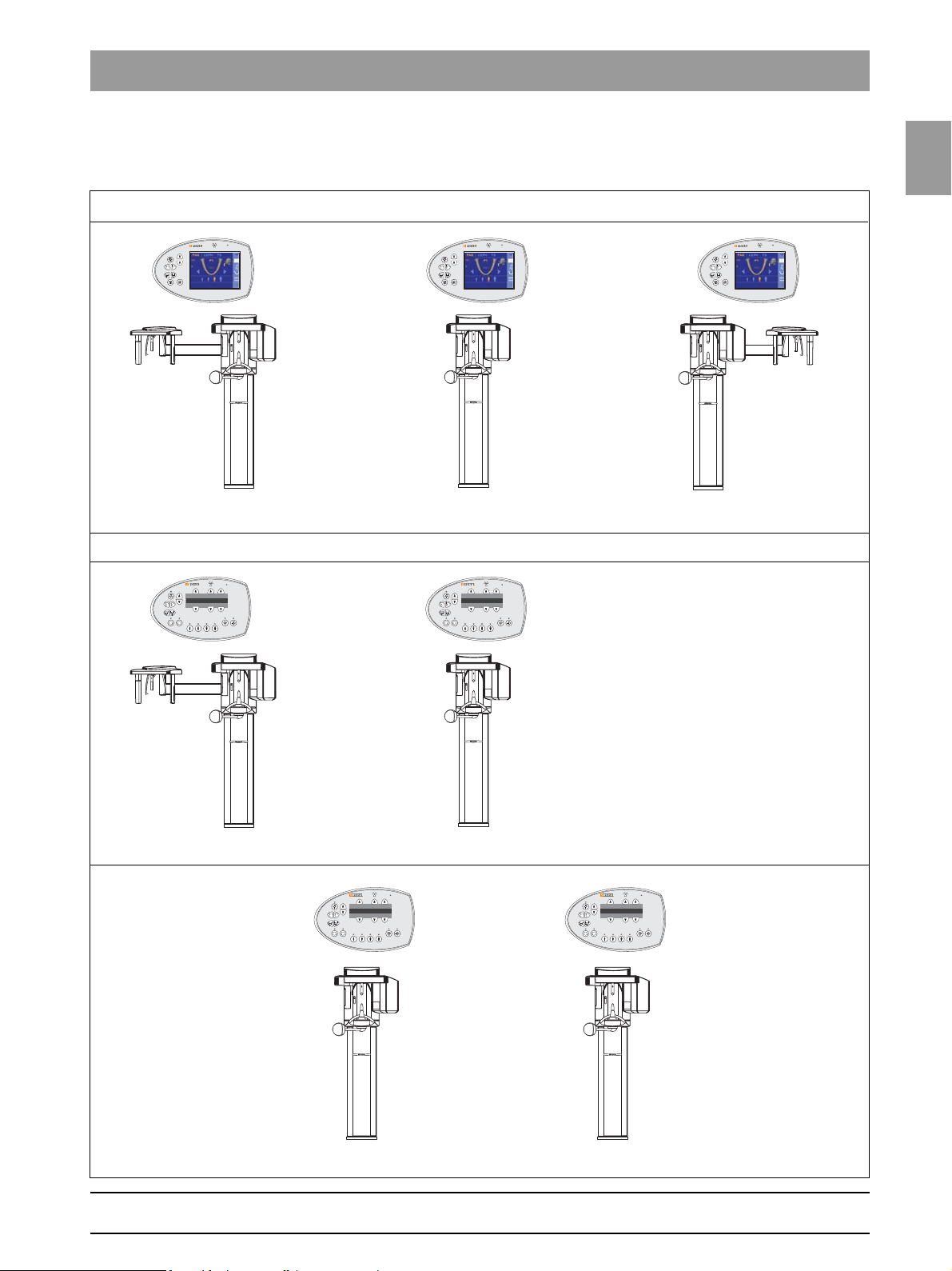
1.2
Device classes XG
Plus
/ 3D
ready
and XG 5 / 3 / 3
PPE
The XG
to their user interface. While the ORTHOPHOS XG (XG
class features a control panel with a color touchscreen (Easypad), the basic
class (XG5/3/3 PPE) is equipped with a simpler control panel with a single-line display (Multipad).
Due to their different control panels, the operating procedures for these two
system classes also vary.
All ORTHOPHOS XG units are digital systems.
The ORTHOPHOS XG
operation with a cephalometer (ceph). The cephalometer for the XG
3D
left or the right side. Only the cephalometer version with the arm mounted on
the left side is offered for the XG 5 system version. Operation of the XG 3/3
PPE system version is not possible with a cephalometer.
The version with the "left-handed arm" is essentially described and illustrated
in this service manual. The installation/removal procedure for the "right-handed arm" version must be performed with laterally reversed orientation where it
is not described separately.
Plus
ready
unit version is also available with the ceph arm mounted either on the
/ 3D
ready
and XG 5 / 3 / 3 PPE system versions differ with regard
Plus
/ 3D
ready
and XG 5 unit versions are suitable for
Plus
/ 3D
ready
) comfort
Plus
/
Remote control operation is possible in all system versions.
The comfort unit class (XG
However, the basic unit class (XG 5/3/3 PPE) is available only in a basic version.
Plus
The XG
This Service Manual describes both system classes in the highest possible
configuration.
For more information on the different installation versions, please refer to the
Installation Instructions.
The empty digits in the single-line display of the Multipad are marked
with underscores in this Manual. They have been added to enhance clarity
and are not present on the real Multipad.
system class optionally includes TSA operation.
Plus
/ 3D
ready
) comes in a basic and a full version.
1 – 6 D3352.076.01.26.02 09.2016
59 38 399 D3352
1.2
Tab 1 1.2 Device classes XG
T
R
Prog.Prog.
S
kV
mA
T
R
Prog.
S
kV
mA
T
R
Prog.
S
kV
mA
ORTHOPHOS XG
Plus
/ 3D
ready
with ceph arm on right sidewith ceph arm on left side
Comfort class (Easypad, basic or full version, TSA option (not for XG 3D
ready
) , remote control option)
ORTHOPHOS XG 5with ceph arm on left side
ORTHOPHOS XG 3
Basic class (Multipad, basic equipment, remote release optional)
T
R
Prog.Prog.
S
kV
mA
ORTHOPHOS XG 3 PPE
1.2.1 Overview of the ORTHOPHOS XG system
classes and versions
Plus
/ 3D
ready
and XG 5 / 3 / 3 PPE
1.2
bеЦдблЬ
59 38 399 D3352
D3352.076.01.26.02 09.2016
1 – 7

1.3 Operation notes Tab 1
1.3
Nominal line voltage The ORTHOPHOS XG X-ray unit can be operated in the following
Nominal line voltage ranges:
200 V - 240 V
50/60 Hz
The permissible line voltage fluctuation at:
200–240 V: ±10%
The internal line impedance must not exceed max. 0.8 Ω.
Operation notes
Fixed connection
Fixed connection
DANGER
Perilous shock hazard!
Fixed connection!
Installing a mains plug instead of the specified fixed connection infringes
international medical regulatory actions and is prohibited. In case of error, this puts patients, users, and other parties seriously at risk.
Remote control The system can be equipped with...
a 1–3m coiled cable with release button inside the treatment room or ...
a remote control with or without coiled cable located outside the X-ray
room (see installation instructions).
Warm-up time After it is switched ON, the system requires a warm-up time of approx. 1 min.
Self-adjustment routine At the same time, a mechanical and electronic self-adjustment routine is exe-
cuted. If a button is pressed during the self-adjustment routine, an error message is displayed on the Multipad (XG5 / 3 / 3 PPE) or on the Easypad (XG
ready
/ 3D
Cooling period The cooling period between two exposures is maintained by an automatic
exposure blocking function according to the pulse/pause ratio. A countdown
of the waiting time is displayed on the Multipad (XG5 / 3 / 3 PPE) or the Easypad (XGXG
Turn-off time The turn-off time must amount to at least 60 s.
Demo units If the X-ray unit is to be presented as a demo unit at trade fairs or exhibitions,
it must be ensured that radiation release is blocked (see "Demo mode – Operation without radiation release" on page 1-11).
Software version The overall system software version is determined by the software statuses of
the EEPROMs on the boards (see "List of software versions" on page 1-14).
Wireless phone interference with medical electrical equipment
Disposal The X-ray tube assembly contains a tube with potential implosion hazard, a
To ensure safe operation of medical electrical equipment, the use of mobile
wireless phones in practice or hospital environments is prohibited.
small amount of beryllium, a lead lining as well as mineral oil.
).
Plus
/ 3D
ready
).
Plus
59 38 399 D3352
1 – 8 D3352.076.01.26.02 09.2016

1.3
Tab 1 1.3 Operation notes
CAUTION
WARNING
Error messages Error messages are displayed on the display of the Multipad (XG5/3/3 PPE)
or on the touchscreen of the Easypad (XG
Help messages in case exposure readiness cannot be attained
If you have to remove covers from the
unit.
Secondary diaphragm Do not manually move or otherwise exert force on the secondary diaphragm
Measurements Always switch the unit OFF before connecting a measuring instrument.
Help messages are displayed on the display of the Multipad (XG5/3/3 PPE)
or on the touchscreen of the Easypad (XG
Proceed according to section "1.13 Remove covers".
When removing covers, always remember that direct sunlight or bright room
lighting can cause system malfunctions due to activated light barriers.
I.e.: avoid direct sunlight and bright room lighting above the unit!
When attaching the covers: Be sure to screw the sheet metal cover back on.
For reasons of electromagnetic compatibility, be sure to fasten all screws.
Reattach the covers.
(e.g. when removing it from its packaging).
Select the correct current/voltage type and adjust the measuring range to
match the expected readings.
Perform continuity tests only on units which are switched off.
Plus
Plus
/ 3D
/ 3D
ready
ready
).
).
1.3
bеЦдблЬ
If several exposures with radiation must be taken to check a measurement,
make sure that the prescribed cool-down intervals are observed. They are
maintained by an automatic exposure blocking function (see Operating
Instructions).
The pulse/pause ratio is 1:10, i.e. a 10-second pause is maintained for each
second of radiation emission. The pulse/pause ratio is automatically maintained (automatic exposure blocking).
A pulse/pause ratio of 1:20 is better for the X-ray tube.
It is essential that you observe the radiation protection regulations applicable in your country prior to radiation release.
The test rotations triggered by pressing the T key on the Easypad and then
the release button are executed without radiation.
59 38 399 D3352
D3352.076.01.26.02 09.2016
1 – 9
1.3 Operation notes Tab 1
Replacing parts Switch off the unit before replacing parts.
When replacing parts in the vicinity of the power connection, the power
switch, board DX32, or the X-ray tube assembly, disconnect the unit from the
distribution box of the building installation.
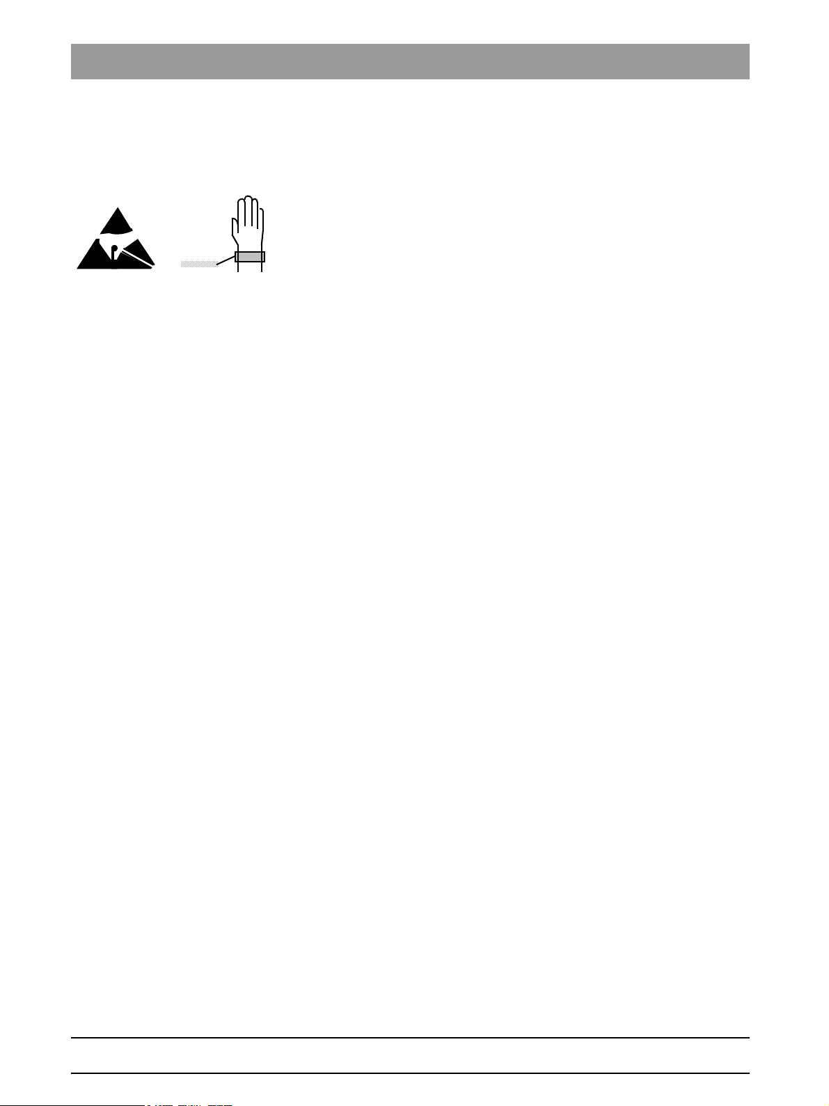
Please always wear an ESD wrist band to protect sensitive components on
printed circuit boards (ESD).
Always check the system and adjust it as required after replacing a board or
the X-ray tube assembly.
The article numbers for ordering spare parts can be found in the spare parts
list, Order No. 59 38 423. The diagrams contained in the spare parts list provide a useful guide when replacing parts.
Safety check A protective ground wire test and a leakage current test must be performed
prior to the installation or the hand-over of the unit as well as after repair work.
See sections "7.14 Checking the protective ground wires " and "7.15 Checking the unit leakage current ".
Functional check Following any form of service and maintenance work, a functional check must
be performed on the device.
Perform the following test steps:
1. Perform a restart of the unit:
– Turn the device off.
– Wait 1 minute.
– Switch the unit on.
– Wait until the self-test is finished.
2. Perform a test exposure using the needle phantom included in the scope
of supply.
59 38 399 D3352
1 – 10 D3352.076.01.26.02 09.2016
1.4
Tab 1 1.4 Demo mode – Operation without radiation release
NOTE
i
A
B
3+4.
1.
2.
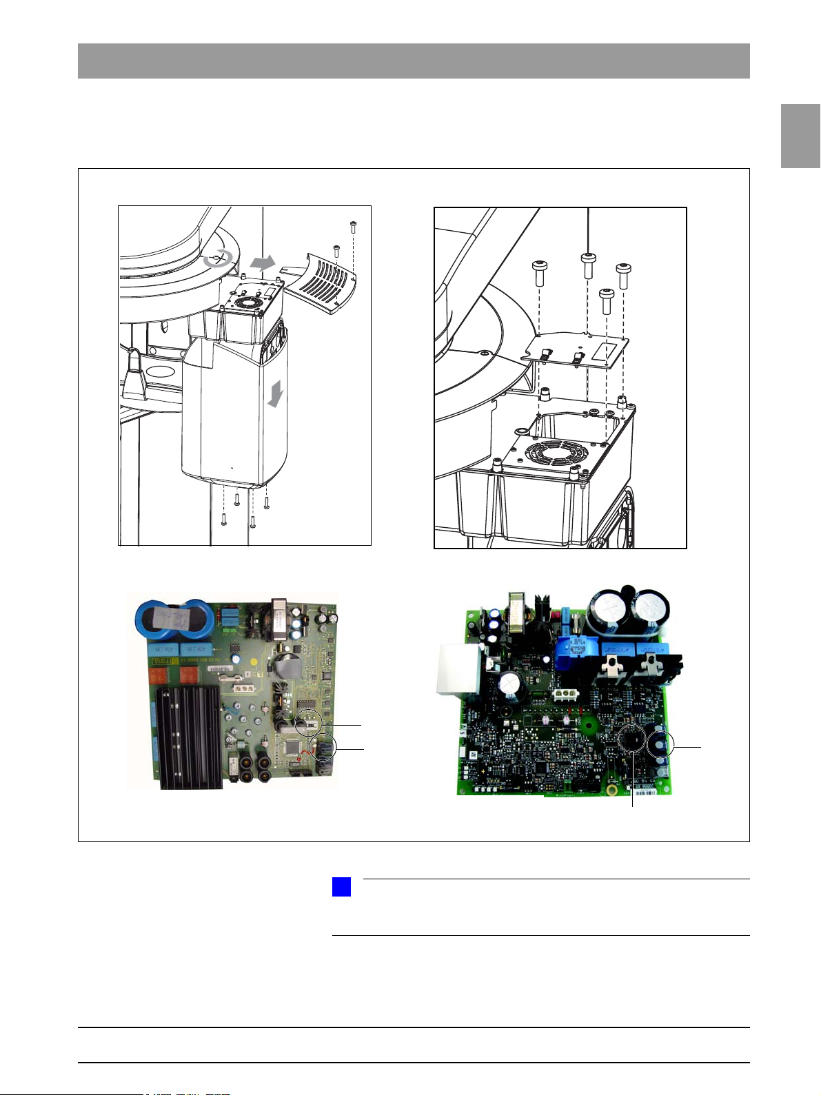
DX6 tube assembly 1.0
J6
S2
3+4.
DX6 tube assembly 2.0
J6
S2
1.4 Demo mode – Operation without radiation
release
1.4
bеЦдблЬ
59 38 399 D3352
D3352.076.01.26.02 09.2016
Starting with system SW version V02.28.02, the complete possible functionality of the system class is simulated, regardless of the current configuration.
1 – 11
1.4 Demo mode – Operation without radiation release Tab 1
DANGER
DANGER
5.
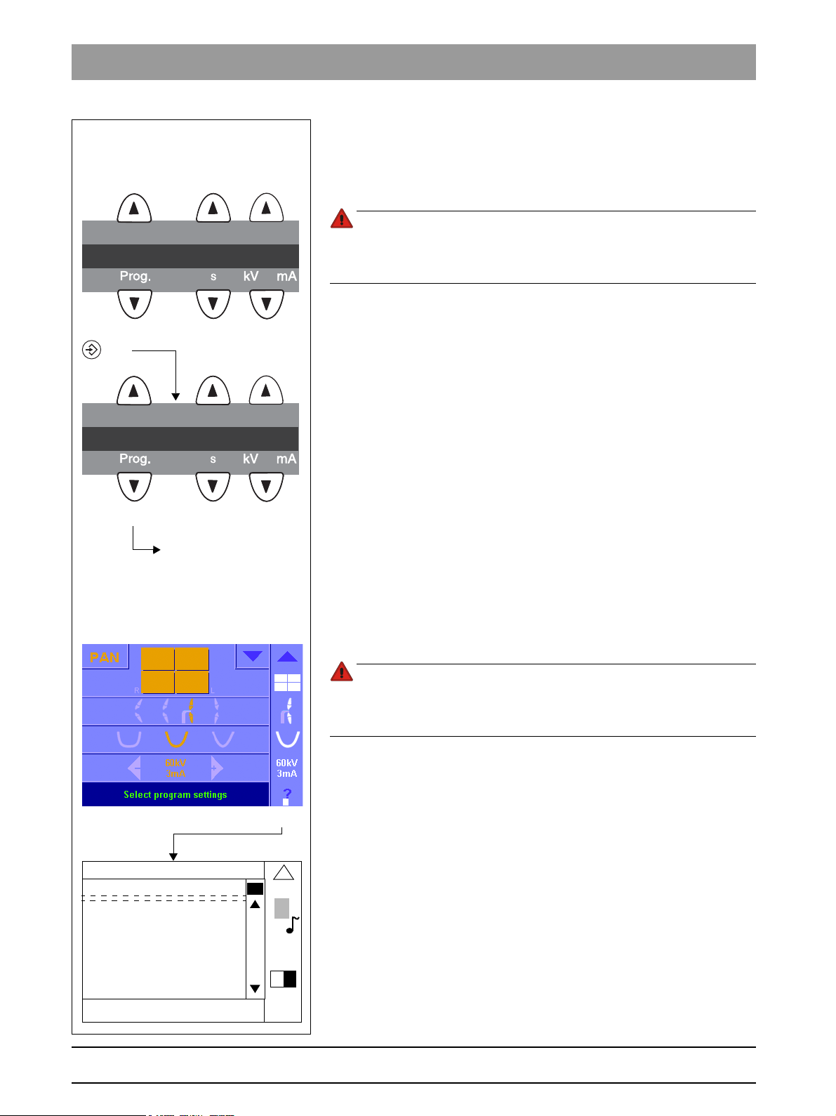
Info menu for XG 5/3
65
Mac address : 010001200000
IP address : 192.168.15.19
Subnet mask : 155.155.255.0
Default gateway : 192.168.15.1
Net API version : 1
Net API revision : 14
Demo mode : ON
Tube exposures : 2217
Orthophos XG configuration
Info screen for XG
Plus
/ 3D
ready
123
P1______14.1__64_8
123
SYSTEM
Scroll through the list
until the demo mode is
displayed
2/2
1.4.1 Switching the demo mode ON
When operated in demo mode, the unit must not release any radiation. For
this reason, you must take the following safety measures:
Turn the device OFF.
PERILOUS SHOCK HAZARD! It is essential to switch the unit off and to
wait at least another minute before taking off the covers of the tube
assembly.
1. Remove the cover of the tube assembly.
2. Loosen the screws (A) and remove the cover plate (B).
3. Set the DIP switch S2 (DX6) to Position 2.
4. Pull the cable L5 (X-RAY) off from connector J6 (DX6).
Radiation release is now no longer possible.
5. Switch the unit ON and check the mode with the
info menu (XG 5 / 3 / 3 PPE) / the info screen (XG
Demo mode: ON means that: The demo mode is switched ON
(Radiation release is not possible)
Demo mode: OFF means: The demo mode is switched OFF
(Radiography, radiation is possible)
Switch the unit OFF again and reattach cover plate B and the tube assem-
bly covers by following the dismantling procedure in reverse order.
Plus
/ 3D
ready
).
1 – 12 D3352.076.01.26.02 09.2016
1.4.2 Switching the demo mode OFF
Turn the device OFF.
PERILOUS SHOCK HAZARD! It is essential to switch off the unit and to
wait at least another 1 minute before taking off the covers of the X-ray
tube assembly.
1. Remove the cover of the tube assembly.
2. Loosen the screws A and remove the cover plate B.
3. Set the DIP switch S2 (DX6) to Position 1.
4. Connect cable L5 (X-RAY) to connector J6 (DX6).
Radiation release is now once again possible.
5. Switch the unit ON and check the mode with the
info menu (XG 5 / 3 / 3 PPE) / the info screen (XG
Demo mode: ON means that: The demo mode is switched ON
(Radiation release is not possible)
Demo mode: OFF means: The demo mode is switched OFF
(Radiography, radiation is possible)
Switch the unit OFF again and reattach cover plate B and the tube assem-
bly covers by following the dismantling procedure in reverse order.
Plus
/ 3D
ready
).
59 38 399 D3352
1.5
Tab 1 1.5 Demo mode – Repacking andtransport
NOTE
i
DANGER
1.
A
NOTE
i
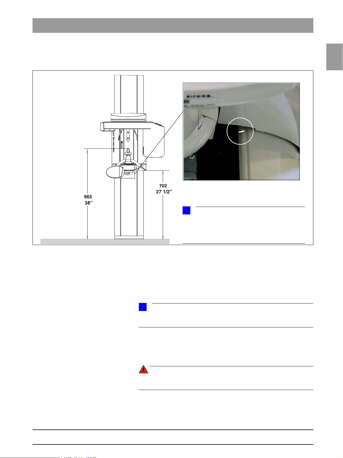
If the unit is installed with a floor stand, its height increases by 30mm. The bite block height value displayed on the Multipad (XG5/3/3 PPE) or Easypad
(XG
Plus
/ 3D
ready
) remains the same, however.
1.5 Demo mode –
Repacking andtransport
1.5
bеЦдблЬ
Panoramic X-ray unit Switch the panoramic X-ray unit ON and move it to its packing height by
pressing the UP/DOWN keys on the Multipad (XG5/3/3 PPE) or Easypad
Plus
(XG
– Bite block height = 965 mm (displayed as height on Multipad (XG5/3/3
PPE) or
Cephalometer Start service routine S034, test step 6.
Easypad (XG
– Bottom edge of slide cover = 702 mm
The bottom edge of the slide cover must be at the same height as the markings A in the column.
Move the cephalometer to the packing position
(see page 5-165).
Turn the device OFF.
PERILOUS SHOCK HAZARD! Prior to disconnecting the line voltage,
you must switch off the power connection and wait 1 minute?.
Unplug any connections between the external units and the DX41 board
or interface board, and disconnect the unit from the power supply.
For information on packing the units and on the packing condition, see the
relevant installation instructions.
/ 3D
ready
).
Plus
/ 3D
ready
) displayed as height)
59 38 399 D3352
D3352.076.01.26.02 09.2016
1 – 13

1.6 List of software versions Tab 1
NOTE
i
1.6
List of software versions
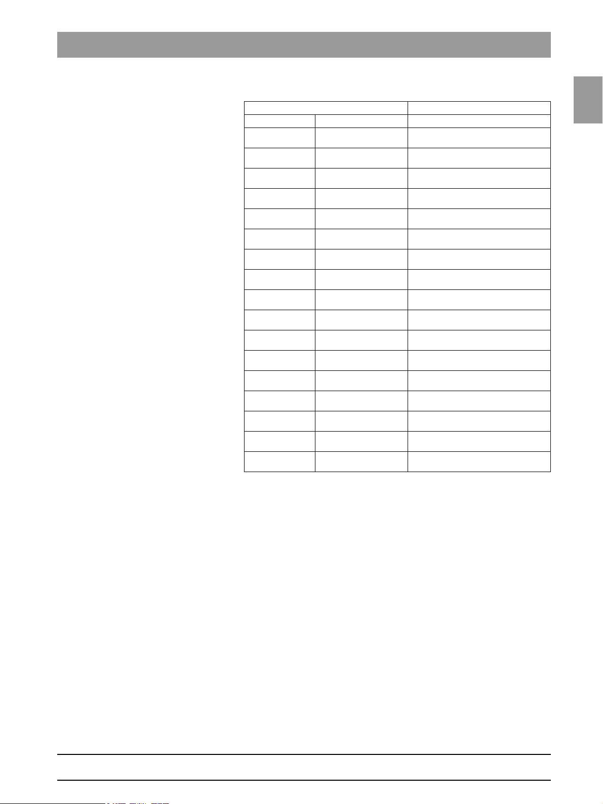
Any software combinations other than those listed here are
not allowed. If the software version of any particular module does not match
the overall software version, the overall software version will be
marked with an asterisk on the info screen (e.g. 02.20*).
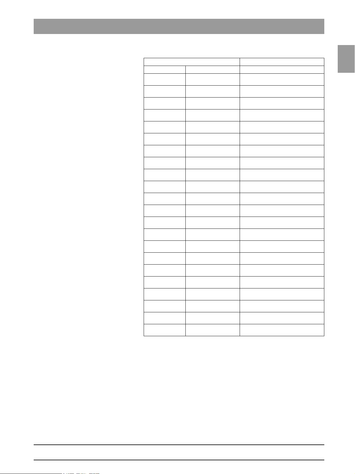
1.6.1 ORTHOPHOS XG 3 PPE
Panoramic unit
Board DX6 DX71 DX11 DX81
Overall software
V 02.28
Overall software
V 02.28.2
Overall software
V 02.30
Overall software
V 02.31
Overall software
V 02.32
Overall software
V 02.35
Overall software
V 02.40
Overall software
V 02.41
Overall software
V 02.41.01
Overall software
V 02.51.01
Overall software
V 02.51.02
Overall software
V 02.51.03
Overall software
V 02.54.00
Overall software
V 02.54.01
Overall software
V 02.58.00
Overall software
V 02.58.02
Tube assem-
bly 1.0
03.06.03 04.07.01
Tube assem-
bly 1.0
03.08.00 04.09.07
Tube assem-
bly 1.0
03.08.00 04.10.06
02.60 02.33 02.40 02.33
02.60 02.33 02.40.01 02.33
02.60 02.34 02.42 02.33
02.60 02.34 02.42 02.33
02.60 02.34 02.43 02.33
02.61 02.35 02.45 02.33
02.61 02.35 02.47 02.33
02.62 02.36 02.48 02.33
02.63 02.37 02.48 02.33
03.05.00 02.54.00 02.51.01 02.33
03.06.00 02.54.00 02.51.02 02.33
03.06.00 02.54.00 02.51.03 02.33
03.06.01 02.54.03 02.54.00 02.33
Tube assem-
bly 2.0
Tube assem-
bly 2.0
Tube assem-
bly 2.0
02.54.03 02.54.01 02.33
02.55.02 02.58.00 02.33
02.55.02 02.59.07 02.33
* Exception: SIDEXIS version V02.00
Note
compatible with
SIDEXIS versions V01.61
compatible with
SIDEXIS versions V01.61
compatible with
SIDEXIS versions V01.61
compatible with
SIDEXIS versions V01.61
compatible with
SIDEXIS versions V01.61
compatible with
SIDEXIS versions V01.61
compatible with
SIDEXIS versions V01.61
compatible with
SIDEXIS versions V01.61
compatible with
SIDEXIS versions V01.61
compatible with
SIDEXIS versions V01.61
compatible with
SIDEXIS Version V01.61*
compatible with
SIDEXIS Version V01.61*
compatible with
SIDEXIS Version V01.61*
compatible with
SIDEXIS Version V01.61*
compatible with
SIDEXIS Version V01.61 – V2.5*
compatible with
SIDEXIS Version V01.61 – V2.5*
59 38 399 D3352
1 – 14 D3352.076.01.26.02 09.2016
1.6
Tab 1 1.6 List of software versions
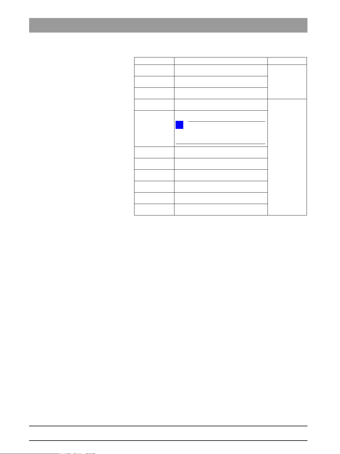
Remote control
Board DX42
Overall software
V 02.28
Overall software
V 02.28.2
Overall software
V 02.30
Overall software
V 02.31
Overall software
V 02.32
Overall software
V 02.35
Overall software
V 02.40
Overall software
V 02.41
Overall software
V 02.41.01
Overall software
V 02.51.01
Overall software
V 02.51.01
Overall software
V 02.51.02
Overall software
V 02.51.03
Overall software
V 02.54.00
Overall software
V 02.54.01
Overall software
V 02.58.00
Overall software
V 02.58.02
02.30
02.30
02.31
02.31
02.31
02.50
02.52
02.52
02.52
02.54.00
02.54.00
02.54.00
02.54.00
02.56.02
02.56.02
02.58.02
02.58.02
Note
1.6
bеЦдблЬ
59 38 399 D3352
D3352.076.01.26.02 09.2016
1 – 15
1.6 List of software versions Tab 1
NOTE
i
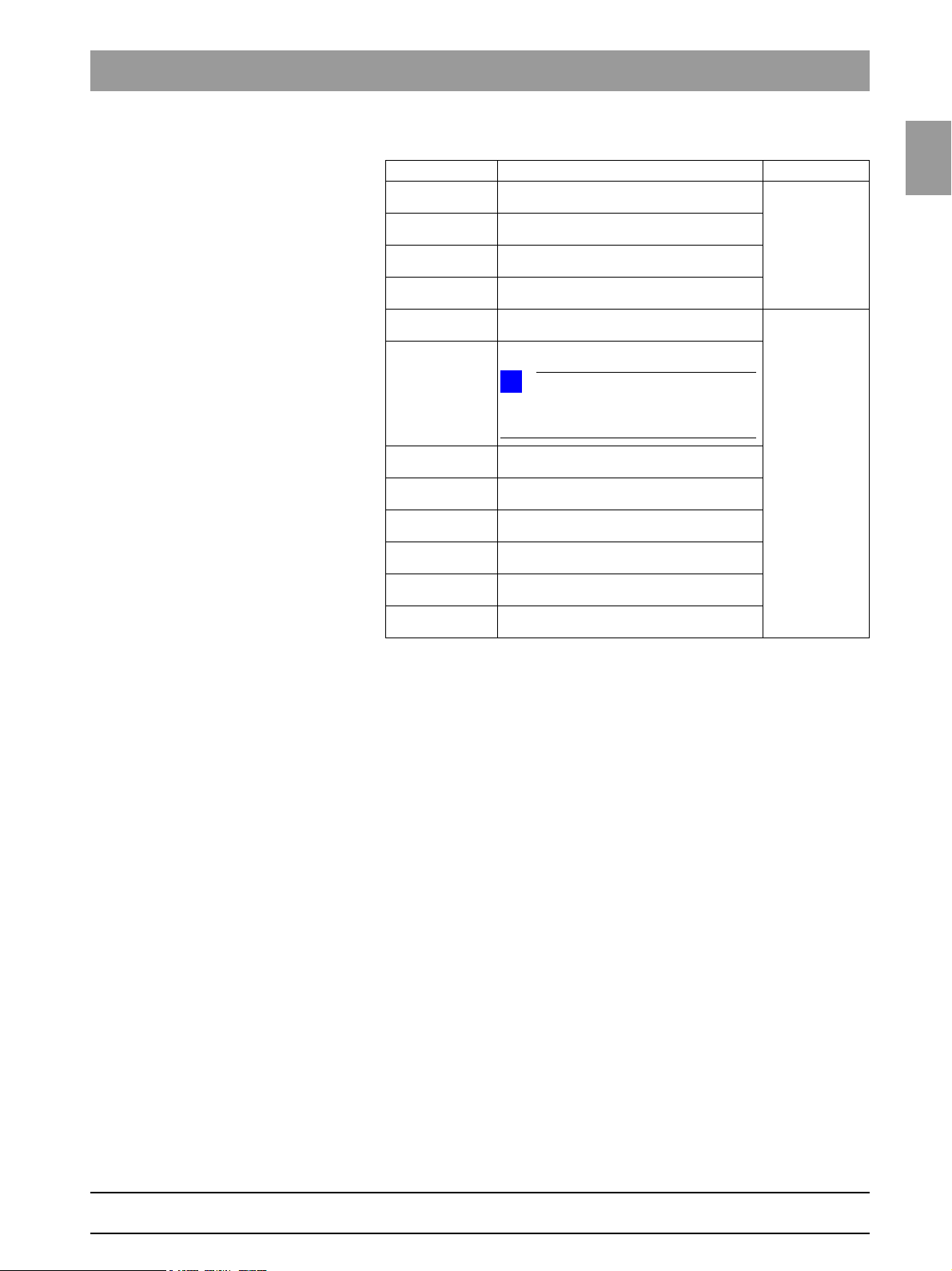
Sidexis XG
V 01.53
V 01.54
V 01.55
V 01.61
V 02.00
V 2.2
V 2.3
V 2.4
V 2.5
V 2.5.3
V 2.5.6
Note Database
requires ORTHOPHOS XG 3 PPE
overall software version V02.28.2 or higher
requires ORTHOPHOS XG 3 PPE
overall software version V02.28.2 or higher
requires ORTHOPHOS XG 3 PPE
overall software version V02.28.2 or higher
requires ORTHOPHOS XG 3 PPE
overall software version V02.28.2 or higher
requires ORTHOPHOS XG 3 PPE
overall software version V02.28.2 or higher
Exception: Overall software V2.51.2 is not
compatible with Sidexis XG version V02.00.
requires ORTHOPHOS XG 3 PPE
overall software version V02.28.2 or higher
requires ORTHOPHOS XG 3 PPE
overall software version V02.28.2 or higher
requires ORTHOPHOS XG 3 PPE
overall software version V02.28.2 or higher
requires ORTHOPHOS XG 3 PPE
overall software version V02.28.2 or higher
requires ORTHOPHOS XG 3 PPE
overall software version V02.28.2 or higher
requires ORTHOPHOS XG 3 PPE
overall software version V02.28.2 or higher
Old database
New database
59 38 399 D3352
1 – 16 D3352.076.01.26.02 09.2016

1.6
Tab 1 1.6 List of software versions
1.6.2 ORTHOPHOS XG 3
Panoramic unit
Board DX6 DX71 DX11 DX41 DX81
Overall software
V 02.25
Overall software
V 02.27
Overall software
V 02.28
Overall software
V 02.28.2
Overall software
V 02.30
Overall software
V 02.31
Overall software
V 02.32
Overall software
V 02.35
Overall software
V 02.41
Overall software
V 02.41.01
Overall software
V 02.51.01
Overall software
V 02.51.02
Overall software
V 02.51.03
Overall software
V 02.54
Overall software
V 02.54.01
Overall software
V 02.58.00
Overall software
V 02.58.01
Overall software
V 02.58.02
Tube assem-
bly 1.0
03.06.03 04.07.01
Tube assem-
bly 1.0
03.08.00 04.09.07
Tube assem-
bly 1.0
03.08.00 04.09.07
Tube assem-
bly 1.0
03.08.00 04.10.06
02.57 02.29 02.37 02.22 02.30
02.60 02.31 02.39 02.23 02.32
02.60 02.33 02.40 (02.23*) 02.33
02.60 02.33 02.40.01 (02.23*) 02.33
02.60 02.34 02.42 (02.23*) 02.33
02.60 02.34 02.42 (02.23*) 02.33
02.60 02.34 02.43 (02.23*) 02.33
02.61 02.35 02.45 (02.23*) 02.33
02.62 02.36 02.48 (02.23*) 02.33
02.63 02.37 02.48 (02.23*) 02.33
03.05.00 02.54.00 02.51.01 02.30.00 02.33
03.06.00 02.54.00 02.51.02 02.30.00 02.33
03.06.00 02.54.00 02.51.03 02.30.00 02.33
03.06.01 02.54.03 02.54.00 02.30.00 02.33
Tube assem-
bly 2.0
Tube assem-
bly 2.0
Tube assem-
bly 2.0
Tube assem-
bly 2.0
02.54.03 02.54.01 02.30.00 02.33
02.55.02 02.58.00 02.30.00 02.33
02.55.02 02.58.00 02.30.00 02.33
02.55.02 02.59.07 02.30.00 02.33
* Exception: SIDEXIS version V02.00
Note
compatible with
SIDEXIS versions V01.45
compatible with
SIDEXIS version V01.53
compatible with
SIDEXIS version V01.53
compatible with
SIDEXIS version V01.53
compatible with
SIDEXIS version V01.53
compatible with
SIDEXIS version V01.53
compatible with
SIDEXIS version V01.53
compatible with
SIDEXIS versions V01.61
compatible with
SIDEXIS versions V01.61
compatible with
SIDEXIS versions V01.61
compatible with
SIDEXIS versions V01.61
compatible with
SIDEXIS Version V01.61*
compatible with
SIDEXIS Version V01.61*
compatible with
SIDEXIS Version V01.61*
compatible with
SIDEXIS Version V01.61*
compatible with
SIDEXIS Version V01.61 –
V2.5*
compatible with
SIDEXIS Version V01.61 –
V2.5*
compatible with
SIDEXIS Version V01.61 –
V2.5*
1.6
bеЦдблЬ
59 38 399 D3352
D3352.076.01.26.02 09.2016
1 – 17

1.6 List of software versions Tab 1
Remote control
Board DX42
Overall software
V 02.25
Overall software
V 02.27
Overall software
V 02.28
Overall software
V 02.28.2
Overall software
V 02.30
Overall software
V 02.31
Overall software
V 02.32
Overall software
V 02.35
Overall software
V 02.40
Overall software
V 02.41
Overall software
V 02.41.01
Overall software
V 02.51.01
Overall software
V 02.51.02
Overall software
V 02.51.03
Overall software
V 02.54.00
Overall software
V 02.54.01
Overall software
V 02.58.00
Overall software
V 02.58.01
Overall software
V 02.58.02
02.27
02.28
02.30
02.30
02.31
02.31
02.31
02.50
02.52
02.52
02.52
02.54.00
02.54.00
02.54.00
02.56.02
02.56.02
02.58.02
02.58.02
02.58.02
Note
59 38 399 D3352
1 – 18 D3352.076.01.26.02 09.2016
1.6
Tab 1 1.6 List of software versions
NOTE
i
Sidexis XG
V 01.51
V 01.53
V 01.54
V 01.55
V 01.61
V 02.00
V 2.2
V 2.3
V 2.4
V 2.5
V 2.5.3
V 2.5.6
Note Database
requires ORTHOPHOS XG 3 overall software
version V02.25 or higher
requires ORTHOPHOS XG 3
overall software version V02.25 or higher
requires ORTHOPHOS XG 3
overall software version V02.25 or higher
requires ORTHOPHOS XG 3 PPE
overall software version V02.28.2 or higher
requires ORTHOPHOS XG 3 overall software
version V02.25 or higher
requires ORTHOPHOS XG 3
overall software version V02.25 or higher
Exception: Overall software V2.51.2 is not
compatible with Sidexis XG version V02.00.
requires ORTHOPHOS XG 3 overall software
version V02.25 or higher
requires ORTHOPHOS XG 3 overall software
version V02.28.2 or higher
requires ORTHOPHOS XG 3 overall software
version V02.28.2 or higher
requires ORTHOPHOS XG 3 overall software
version V02.28.2 or higher
requires ORTHOPHOS XG 3 overall software
version V02.28.2 or higher
requires ORTHOPHOS XG 3 PPE
overall software version V02.28.2 or higher
Old database
New database
1.6
bеЦдблЬ
* As of hardware version BA (from November 2006) new systems will be delivered without
board DX41 (see also page 1-44).
59 38 399 D3352
D3352.076.01.26.02 09.2016
1 – 19

1.6 List of software versions Tab 1
1.6.3 ORTHOPHOS XG 5 / Ceph
Panoramic unit Cephalo-
Board DX6 DX71 DX11 DX41 DX61 DX81 DX91
Overall software
V 02.18.1
Overall software
V 02.20
Overall software
V 02.22
Overall software
V 02.25
Overall software
V 02.27
Overall software
V 02.28
Overall software
V 02.28.2
Overall software
V 02.30
Overall software
V 02.31
Overall software
V 02.32
Overall software
V 02.35
Overall software
V 02.40
Overall software
V 02.41
Overall software
V 02.41.01
Overall software
V 02.51.01
Overall software
V 02.51.02
Overall software
V 02.51.03
Overall software
V 02.54
Overall software
V 02.54.01
Overall software
V 02.58.00
Overall software
V 02.58.01
Overall software
V 02.58.02
02.45 02.23 02.31 02.19 02.20 02.25 02.32
02.56 02.28 02.33 02.22 02.26 02.29 02.34
02.56 02.28 02.35 02.22 02.30 02.29 02.38
02.57 02.29 02.37 02.22 02.30 02.30 02.40
02.60 02.31 02.39 02.23 02.33 02.32 02.42
02.60 02.33 02.40 (02.23*) 02.33 02.33 02.42
02.60 02.33 02.40.01 (02.23*) 02.34 02.33 02.43
02.60 02.34 02.42 (02.23*) 02.34 02.33 02.43
02.60 02.34 02.42 (02.23*) 02.34 02.33 02.44
02.60 02.34 02.43 (02.23*) 02.35 02.33 02.44
02.61 02.35 02.45 (02.23*) 02.35 02.33 02.44
02.61 02.35 02.47 (02.23*) 02.35 02.33 02.44
02.62 02.36 02.48 (02.23*) 02.35 02.33 02.44
02.63 02.37 02.48 (02.23*) 02.35 02.33 02.44
03.05.00 02.54.00 02.51.01 02.30.00 04.01.00 02.33 02.44.00
03.06.00 02.54.00 02.51.02 02.30.00 04.01.00 02.33 02.44.00
03.06.00 02.54.00 02.51.03 02.30.00 04.01.00 02.33 02.44.00
03.06.01 02.54.03 02.54.00 02.30.00 04.02.00 02.33 02.44.00
Tube
assem-
bly 1.0
03.06.03 04.07.01
Tube
assem-
bly 1.0
03.08.00 04.09.07
Tube
assem-
bly 1.0
03.08.00 04.09.07
Tube
assem-
bly 1.0
03.08.00 04.10.06
Tube
assem-
bly 2.0
Tube
assem-
bly 2.0
Tube
assem-
bly 2.0
Tube
assem-
bly 2.0
02.54.03 02.54.01 02.30.00 04.02.00 02.33 02.44.00
02.55.02 02.58.00 02.30.00 04.04.00 02.33 02.45.00
02.55.02 02.58.00 02.30.00 04.04.00 02.33 02.45.00
02.55.02 02.59.07 02.30.00 04.04.00 02.33 02.45.00
* Exception: SIDEXIS version V02.00
meter
Note
compatible with SIDEXIS versions up to and incl. V01.44
compatible with
SIDEXIS versions V01.45
compatible with
SIDEXIS versions V01.45
compatible with
SIDEXIS versions V01.45
compatible with
SIDEXIS version V01.53
compatible with
SIDEXIS version V01.53
compatible with
SIDEXIS version V01.53
compatible with
SIDEXIS version V01.53
compatible with
SIDEXIS version V01.53
compatible with
SIDEXIS version V01.53
compatible with
SIDEXIS version V01.53
compatible with
SIDEXIS versions V01.61
compatible with
SIDEXIS versions V01.61
compatible with
SIDEXIS versions V01.61
compatible with
SIDEXIS versions V01.61
compatible with
SIDEXIS Version V01.61*
compatible with
SIDEXIS Version V01.61*
compatible with
SIDEXIS Version V01.61*
compatible with
SIDEXIS Version V01.61*
compatible with
SIDEXIS Version V01.61 –
V2.5*
compatible with
SIDEXIS Version V01.61 –
V2.5*
compatible with
SIDEXIS Version V01.61 –
V2.5*
59 38 399 D3352
1 – 20 D3352.076.01.26.02 09.2016
1.6
Tab 1 1.6 List of software versions
Remote control
Board DX42
Overall software
V 02.18.1
Overall software
V 02.20
Overall software
V 02.22
Overall software
V 02.25
Overall software
V 02.27
Overall software
V 02.28
Overall software
V 02.28.2
Overall software
V 02.30
Overall software
V 02.31
Overall software
V 02.32
Overall software
V 02.35
Overall software
V 02.40
Overall software
V 02.41
Overall software
V 02.41.01
Overall software
V 02.51.01
Overall software
V 02.51.02
Overall software
V 02.51.03
Overall software
V 02.54.00
Overall software
V 02.54.01
Overall software
V 02.58.00
Overall software
V 02.58.01
Overall software
V 02.58.02
02.22
02.27
02.27
02.27
02.28
02.30
02.30
02.31
02.31
02.31
02.50
02.52
02.52
02.52
02.54.00
02.54.00
02.54.00
02.56.02
02.56.02
02.58.02
02.58.02
02.58.02
Note
1.6
bеЦдблЬ
59 38 399 D3352
D3352.076.01.26.02 09.2016
1 – 21
1.6 List of software versions Tab 1
NOTE
i
Sidexis XG
V 01.33 - V01.44
V 01.45
V 01.50
V 01.51
V 01.53
V 01.54
V 01.55
V 01.61
V 02.00
V 2.2
V 2.3
V 2.4
V 2.5
V 2.5.3
V 2.5.6
* As of hardware version BA (from November 2006) new systems will be delivered without
board DX41 (see also page 1-44).
Note Database
requires ORTHOPHOS XG 5 overall
software version < V02.20
requires ORTHOPHOS XG 5 overall
software version V02.20 or higher
requires ORTHOPHOS XG 5 overall
software version V02.20 or higher
requires ORTHOPHOS XG 5 overall
software version V02.20 or higher
requires ORTHOPHOS XG 5 overall
software version V02.20 or higher
requires ORTHOPHOS XG 5 overall
software version V02.20 or higher
requires ORTHOPHOS XG 5
overall software version V02.28.2 or
higher
requires ORTHOPHOS XG 5 overall
software version V02.20 or higher
requires ORTHOPHOS XG 5 overall
software version V02.20 or higher
Exception: Overall software V2.51.2 is
not compatible with Sidexis XG version
V02.00.
requires ORTHOPHOS XG 5 overall
software version V02.20 or higher
requires ORTHOPHOS XG 5 overall
software version V02.28.2 or higher
requires ORTHOPHOS XG 5
overall software version V02.28.2 or
higher
requires ORTHOPHOS XG 5
overall software version V02.28.2 or
higher
requires ORTHOPHOS XG 5
overall software version V02.28.2 or
higher
requires ORTHOPHOS XG 3 PPE
overall software version V02.28.2 or
higher
Old database
New database
59 38 399 D3352
1 – 22 D3352.076.01.26.02 09.2016
Loading...