


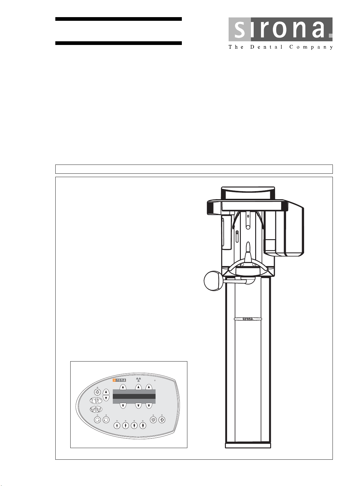
Orthophos XG3
NMKOMNR
bеЦдблЬ
kÉï=~ë=çÑW=
loqelmelp=ud=P=
fелн~дд~нбзе=fелнкмЕнбзел
T
R
Prog.
S
kV
mA
P1

kÉï=~ë=çÑW=
NMKOMNR
Sirona Dental Systems GmbH
Installation Instructions ORTHOPHOS XG 3
60 51 416 D 3352
D 3352.031.03.18.02
Changes since the last version 07.2013:
Chapter or section page
6.2 Checking the device leakage current .................... 63
About this document
This document describes the installation of the ORTHO
-
PHOS XG XG3 panoramic X-ray unit.
For installation, please refer also to the following docu
-
ments:
• Installation drawings
• "Installation Requirements" (separate document)
• Operating Instructions
•Service Manual
• Installation Report and Warranty Passport
• SIDEXIS XG, Digital Radiography:
Installation instructions
Our Customer Service Center can provide the technical
documentation in paper form free of charge on request pro
-
vided that the respective order numbers are specified cor
-
rectly.
The latest documentation can always be downloaded from
the Sirona homepage:
www.sirona.com/HOME/Service/Technical Documentation
General information

Sirona Dental Systems GmbH
Installation Instructions ORTHOPHOS XG 3
60 51 416 D 3352
D 3352.031.03.18.02
English
1 Before you begin ............................................................................................................... 5
1.1 Identification of warnings ......................................................................... 6
1.2 Safety....................................................................................................... 7
1.3 System and sensor versions.................................................................... 8
1.4 Dimensions/Space requirements............................................................. 9
1.5 Mounting options ................................................................................... 10
1.6 Installation versions ............................................................................... 11
2 Delivery and transport .................................................................................................... 13
2.1 Delivery.................................................................................................. 14
2.2 Transport to the installation site............................................................. 18
3 Installation: Panoramic X-ray unit ................................................................................. 19
3.1 Installation material................................................................................ 20
3.2 Required tools........................................................................................ 22
3.3 Wall mounting (standard/option 1)......................................................... 23
3.4 Installing the floor stand (option 2)......................................................... 30
3.5 Removing the transport safety device ................................................... 40
3.6 Installing the release button holder........................................................ 41
3.7 Attaching the covers .............................................................................. 42
4 Electrical connection ...................................................................................................... 45
4.1 Connecting the control cables (PAN)..................................................... 46
4.2 Connecting the line voltage ................................................................... 47
5 Installation: Remote control........................................................................................... 49
5.1 Installation material/tools ....................................................................... 50
5.2 Mechanical installation........................................................................... 51
5.3 Connecting the control cables (REMOTE)............................................. 53
5.4 Connecting the door contact switch....................................................... 56
5.5 Connecting the X-ray warning lamp....................................................... 57
5.6 Final work .............................................................................................. 58
6 Safety checks................................................................................................................... 59
6.1 Checking the protective ground wires.................................................... 60
6.2 Checking the device leakage current..................................................... 63
7 Initial startup.................................................................................................................... 65
7.1 Inserting the forehead and temple supports .......................................... 66
7.2 Inserting the sensor ............................................................................... 67
7.3 Switching the units ON .......................................................................... 68
7.4 Checking the data paths ........................................................................ 69
Contents

Sirona Dental Systems GmbH
Installation Instructions ORTHOPHOS XG 3
60 51 416 D 3352
D 3352.031.03.18.02
8 Startup for USA/Canada only ......................................................................................... 73
8.1 Startup, measurements and controls ..................................................... 74
8.2 Power supply adequacy ......................................................................... 75
8.3 Tube Current Verification ....................................................................... 76
8.4 kV – verification / Exposure Time Verification........................................ 79
8.5 Checking the laser for USA/Canada only............................................... 81
9 Checking the system adjustment .................................................................................. 83
9.1 Test exposures....................................................................................... 84
10 Final work......................................................................................................................... 91
10.1 Attaching the profile covers.................................................................... 92
10.2 Selecting More details............................................................................ 93
10.3 Declaration of Conformity....................................................................... 94
10.4 Unit handover......................................................................................... 95
11 Appendix .......................................................................................................................... 97
11.1 Service routines (for installation)............................................................ 98
11.2 Adjusting the panoramic X-ray unit ...................................................... 109
11.3 Demo mode.......................................................................................... 136

ORTHOPHOS XG 3
60 51 416 D 3352
D 3352.031.03.18.02
5
1 Before you begin
1 Before you begin Sirona Dental Systems GmbH
1.1 Identification of warnings Installation Instructions ORTHOPHOS XG 3
60 51 416 D 3352
6 D 3352.031.03.18.02
Warning and safety information
To prevent personal injury and material damage, please
observe the warning and safety information provided in the
present operating instructions.
The structure, appearance and use of warning and safety
information in Sirona documents are based on the ANSI
Z535 standard.
The following warnings may be used in this document:
DANGER
An imminent danger that could result in serious bodily
injury or death.
WARNING
A possibly dangerous situation that can result in seri
-
ous bodily injury or death.
CAUTION
A possibly dangerous situation that can result in slight bodi
-
ly injury.
NOTICE
A possibly harmful situation which can lead to damage of
the product or an object in its environment.
Instructions for use
The following application information may be used in this
document:
IMPORTANT
Application instructions and other important information.
Tip: Information on making work easier.
1.1 Identification of warnings
Sirona Dental Systems GmbH 1 Before you begin
Installation Instructions ORTHOPHOS XG 3 1.2 Safety
60 51 416 D 3352
D 3352.031.03.18.02
7
English
DANGER
Fixed connection!
The installation of a power plug instead of the pre
-
scribed fixed (hard-wired) connection violates interna
-
tional medical regulations and is prohibited.
In case of a fault, you would thus endanger the life and
limb of the patient, the operator or other persons.
WARNING
Installation and startup must be carried out in accor
-
dance with the requirements stated in our Installation
Instructions.
WARNING
Installation and startup may be carried out only by per
-
sonnel specifically authorized by SIRONA.
WARNING
Any person who assembles or modifies a medical elec
-
trical system complying with the standard IEC 60
601-1-1
(safety requirements for medical electrical equipment)
by combining it with other equipment is responsible for
ensuring that the requirements of this regulation are
met to their full extent for the safety of the patients, the
operators and the environment.
If any equipment not approved by SIRONA is connect
-
ed, it must comply with the applicable standards:
- IEC 60950-1 for information technology equipment
and
- IEC 60 601-1 for medical electrical equipment.
See also “On-site installation, dimensions, technical
data” and the “Compatibility list/Declaration of
conformity” issued by the system integrator.
In case of doubt, contact the manufacturer of the sys
-
tem components.
WARNING
Wireless phone interference with medical electrical
equipment:
To ensure safe operation of medical electrical equip
-
ment, the use of mobile wireless phones in practice or
hospital environments is prohibited.
CAUTION
The unit contains class 1 lasers.
Keep a distance of at least 4" (10 cm) between eye and la
-
ser. Do not stare into the beam.
Do not use the system with any other lasers, and do not
make any changes to settings or processes that are not de
-
scribed in these operating instructions. This may lead to a
dangerous exposure to radiation.
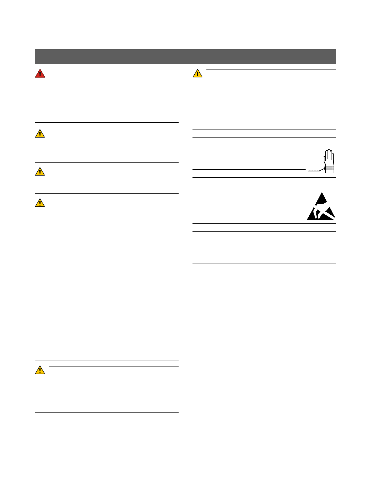
NOTICE
Use an ESD wrist band during installation.
Connect it to the
protective ground wire.
NOTICE
When opening the unit:
Please observe the usual precautionary
measures for handling PCBs (ESD).
Touch a ground point to discharge static elec
-
tricity before handling any components.
NOTICE
Extreme fluctuations of temperature may cause condensa
-
tion inside the unit. Do not switch the unit on before it has
reached normal room temperature.
1.2 Safety
1 Before you begin Sirona Dental Systems GmbH
1.3 System and sensor versions Installation Instructions ORTHOPHOS XG 3
60 51 416 D 3352
8 D 3352.031.03.18.02
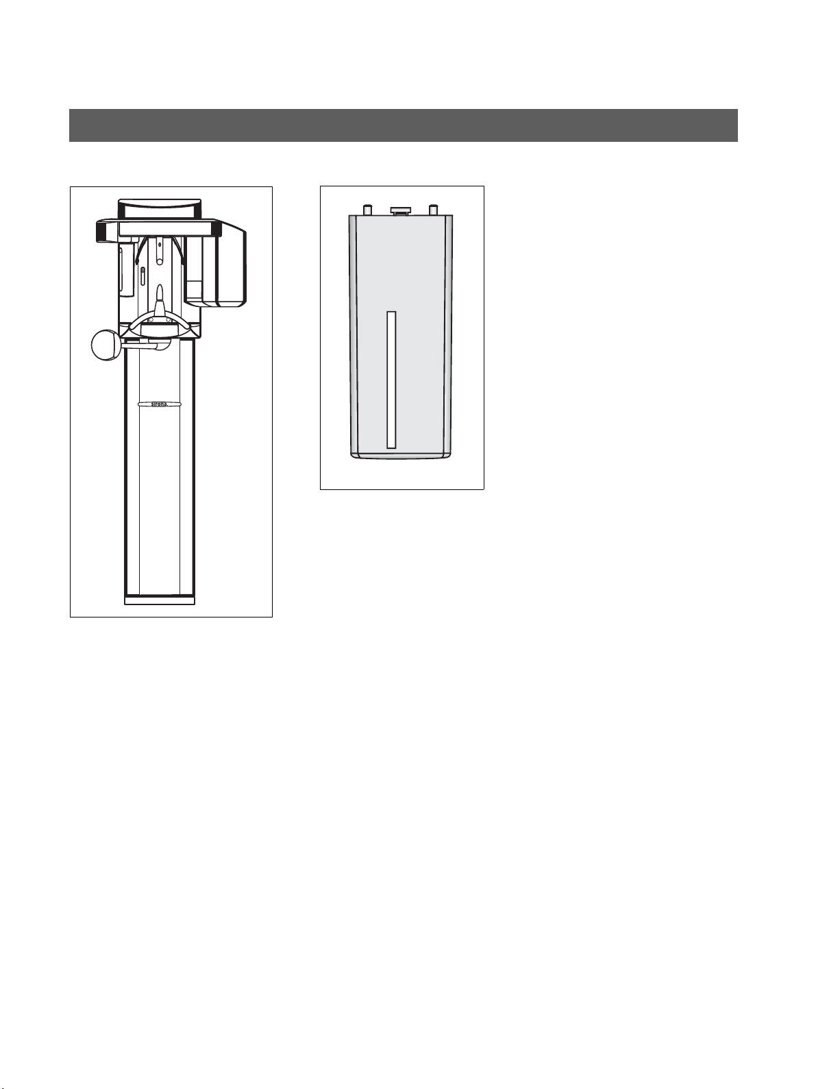
1. ORTHOPHOS XG 3
Digital unit
2. XG PAN sensor
Sensor for panoramic (PAN) X-ray
1.3 System and sensor versions
1.
2.

Sirona Dental Systems GmbH 1 Before you begin
Installation Instructions ORTHOPHOS XG 3 1.4 Dimensions/Space requirements
60 51 416 D 3352
D 3352.031.03.18.02
9
English
NOTICE
The minimum ceiling height should be 2.10 m (82 11/16"). If
the ceiling height is lower than 2.27 m (89 3/8“) (max. travel
height of 2.25 m (88 1/2“)), the travel height of the unit must
be adjusted or limited prior to startup of the unit (see section
11.1.7). )
NOTICE
The dimensions specified here apply to installation of the
X-ray unit without the floor stand. Installation with the floor
stand results in an additional 30 mm (1 3/16“) increase of all
height dimensions.
1.4 Dimensions/Space requirements
1 Before you begin Sirona Dental Systems GmbH
1.5 Mounting options Installation Instructions ORTHOPHOS XG 3
60 51 416 D 3352
10 D 3352.031.03.18.02
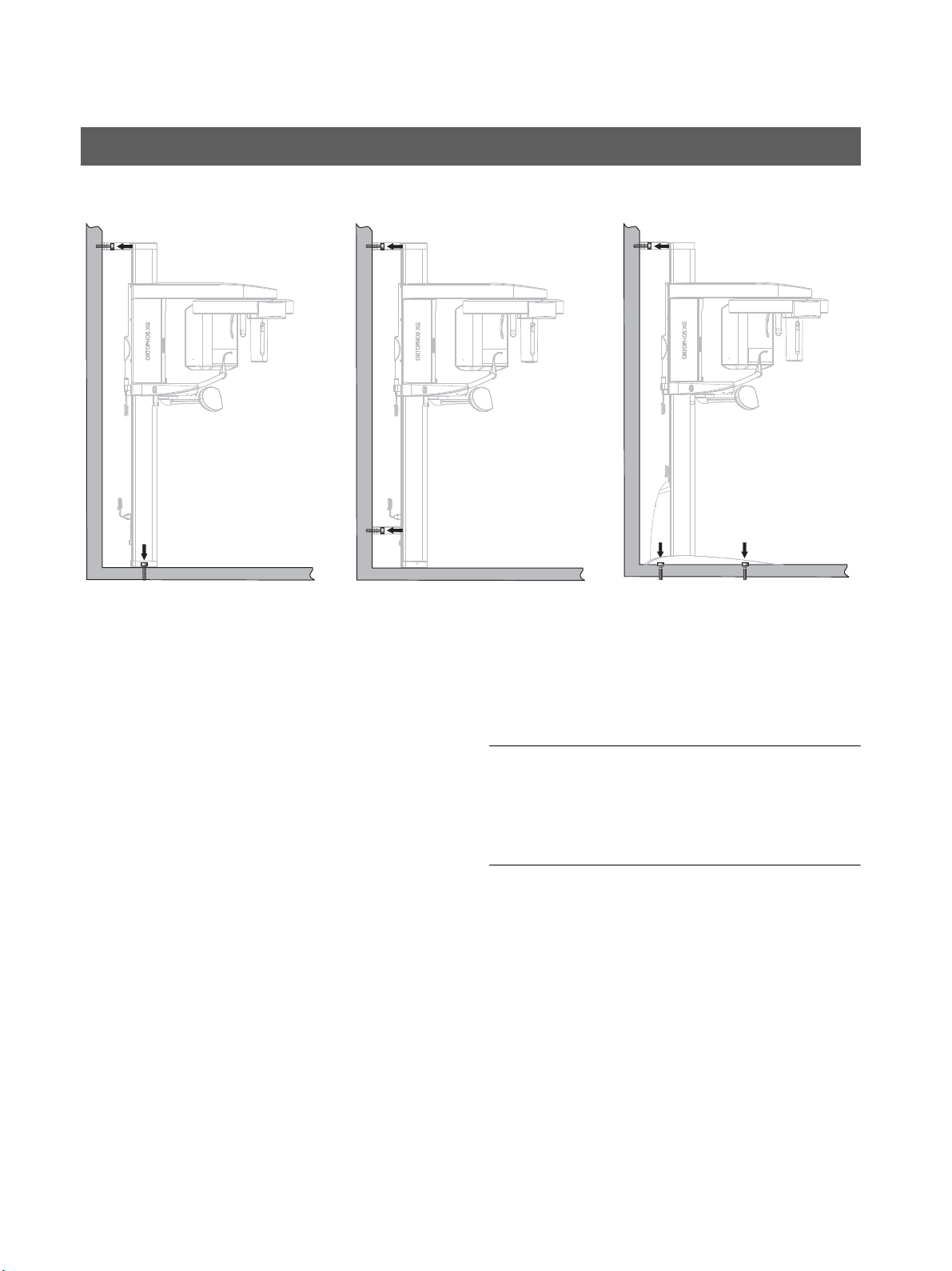
Standard version
(see Section 3.3)
1. Wall-mounted installation with 1 wall holder and
floor fastening if both wall and floor installation are
possible on-site.
Option 1: with second wall holder
(see Section 3.3)
2. Wall-mounted installation with 2 wall holders (and
no floor fastening) if only wall installation is possible
on-site.
Option 2: with floor stand
(see section 3.4)
3. Installation with floor stand for free installation any
-
where in the room or if wall-mounted installation is not
possible on-site (e.g. with lightweight walls).
IMPORTANT
If the unit is installed freely with a floor stand, the quality of
the resulting X-ray exposures may be impaired,
depending on the floor or surface conditions. Sirona there
-
fore recommends additional fastening of the unit with an up
-
per wall holder also when installing it with a floor stand.
1.5 Mounting options
1. 3.2.
Standard version Option 1 Option 2
Sirona Dental Systems GmbH 1 Before you begin
Installation Instructions ORTHOPHOS XG 3 1.6 Installation versions
60 51 416 D 3352
D 3352.031.03.18.02
11
English
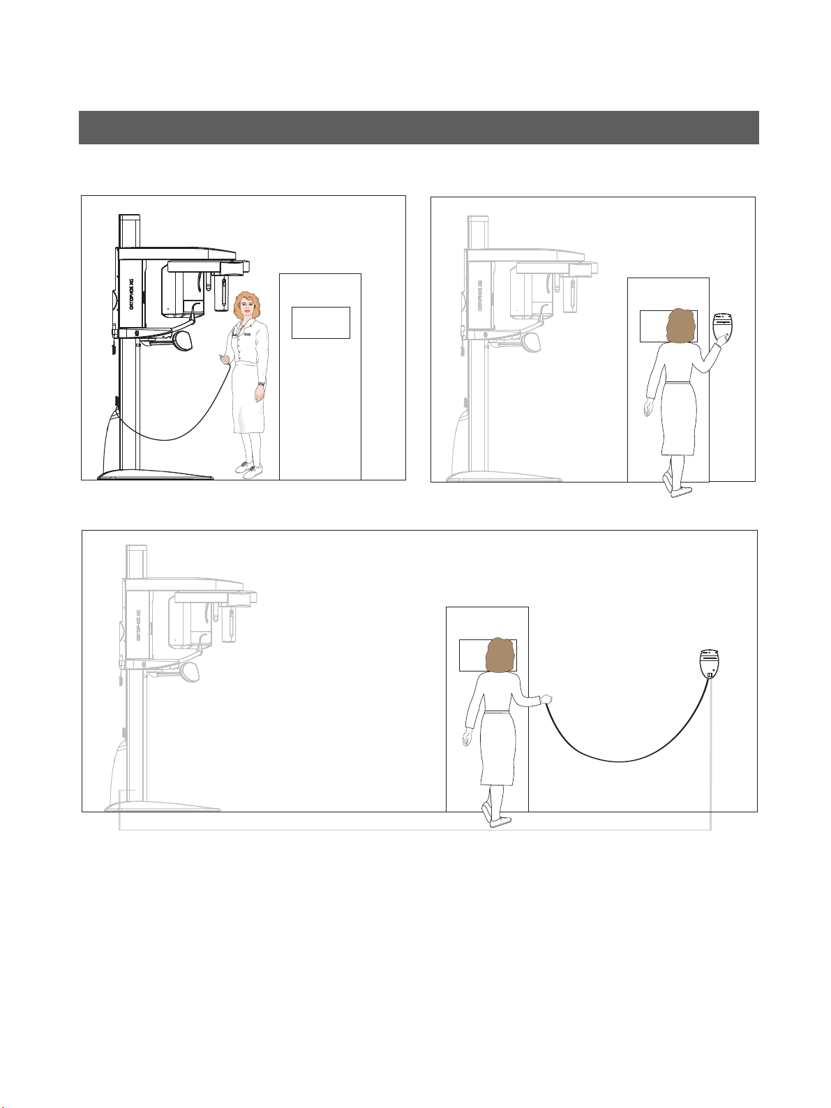
1. Standard installation:
ORTHOPHOS XG 3 without remote control with re
-
lease button on the coiled cable in the treatment
room.
2. Installation version 1 (see section 5.3.1):
ORTHOPHOS XG 3 with remote control outside the
X-ray room without release button on the coiled ca
-
ble.
3. Installation version 2 (see section 5.3.2):
ORTHOPHOS XG 3 with remote control outside the
X-ray room with release button on the coiled cable.
1.6 Installation versions
1. 2.
3.

1 Before you begin Sirona Dental Systems GmbH
1.6 Installation versions Installation Instructions ORTHOPHOS XG 3
60 51 416 D 3352
12 D 3352.031.03.18.02

ORTHOPHOS XG 3
60 51 416 D 3352
D 3352.031.03.18.02
13
2 Delivery and transport
2 Delivery and transport Sirona Dental Systems GmbH
2.1 Delivery Installation Instructions ORTHOPHOS XG 3
60 51 416 D 3352
14 D 3352.031.03.18.02
NOTICE
Possible transport damage!
If the shipment was damaged during transport, document
all damage carefully and contact the responsible carrying
agent immediately.
All SIRONA equipment is carefully checked and packed
prior to shipment. Please carry out an incoming inspection
of the equipment in order to make sure that it was not dam
-
aged during transport.
• Check the packaging and the equipment for visible
signs of damage.
• Check the shipment for completeness based on the at
-
tached “scope of supply” checklist.
IMPORTANT
Disposal: Return the packaging materials to SIRONA or
dispose of them in compliance with the legal regulations ap
-
plicable in your country.
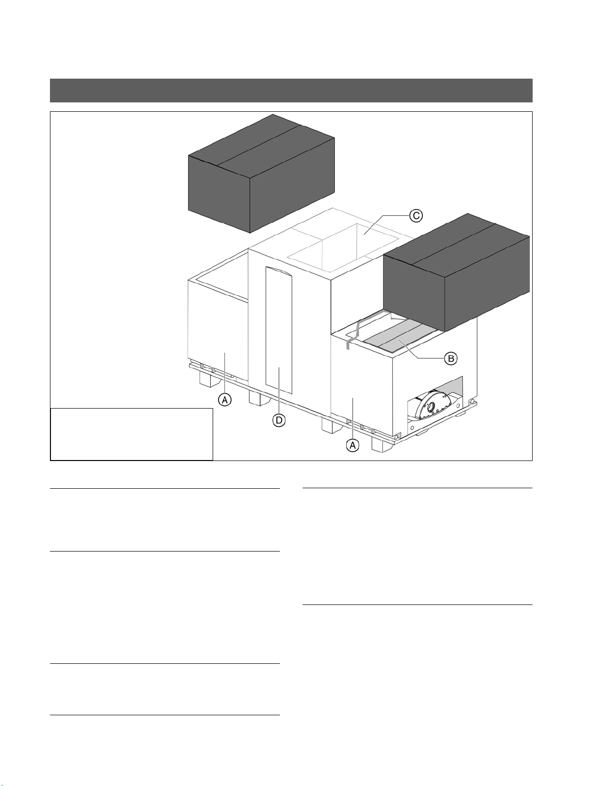
IMPORTANT
The packaging of the X-ray unit is designed both for protec
-
tion during transport and as an installation aid.
Therefore, please remove only the surrounding packaging
prior to installation. Please leave the styrofoam packaging
and transport pallet attached to the unit.
Save one of the lateral styrofoam packaging parts for
later use as an installation aid A.
Scope of supply
• Panoramic X-ray unit
• Profile cover (D)
•Sensor (B)
• Accessories and hygienic protective covers (see pp.
16 ff.) (B)
• Installation material (see section 3.1) (B)
• Safety strap (B)
• Remote control (optional) (C)
2.1 Delivery
Dimensions (cm): 199 x 69 x 122
Weight: 177 kg (390 lbs)
(inches): 78 3/8 x 30 3/4 x 28 3/4
Sirona Dental Systems GmbH 2 Delivery and transport
Installation Instructions ORTHOPHOS XG 3 2.1 Delivery
60 51 416 D 3352
D 3352.031.03.18.02
15
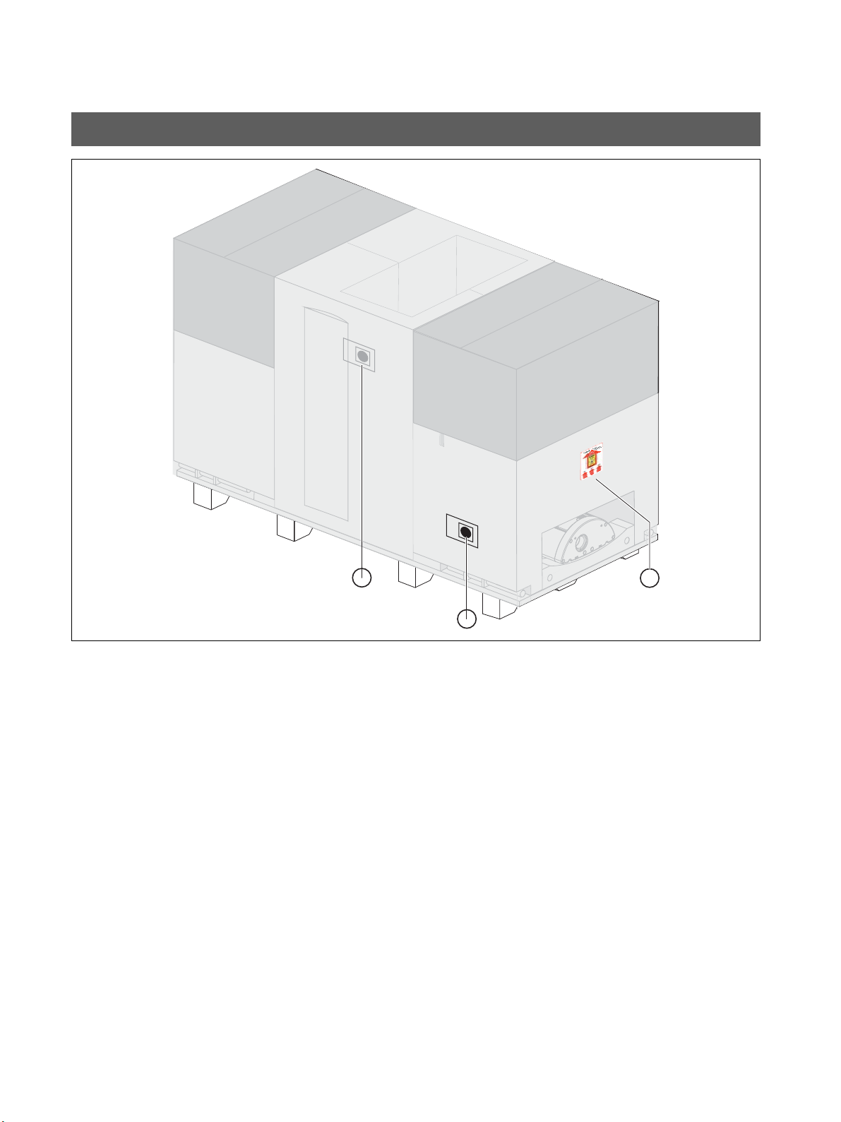
Tw o shock indicators A are attached to the side of the
packaging to indicate whether the unit was exposed to a
shock during transport.
• White indicator: No shock
• Red indicator: Shock
A tilt indicator B that enables you to recognize whether the
unit was transported improperly is also attached to the
packaging.
• Red indicator: Improper transport
The display of improper transport doesn't necessarily mean
that the unit is damaged.
Make a note on the delivery slip that the indicator is acti
-
vated. Have this confirmed on the delivery note by the driver
of the transport company.
Fax the delivery slip to the Sirona Customer Service Center
(CSC).
Enter the state of the indicators in the startup report in the
case of warranty claims.
A
A
B
2 Delivery and transport Sirona Dental Systems GmbH
2.1 Delivery Installation Instructions ORTHOPHOS XG 3
60 51 416 D 3352
16 D 3352.031.03.18.02
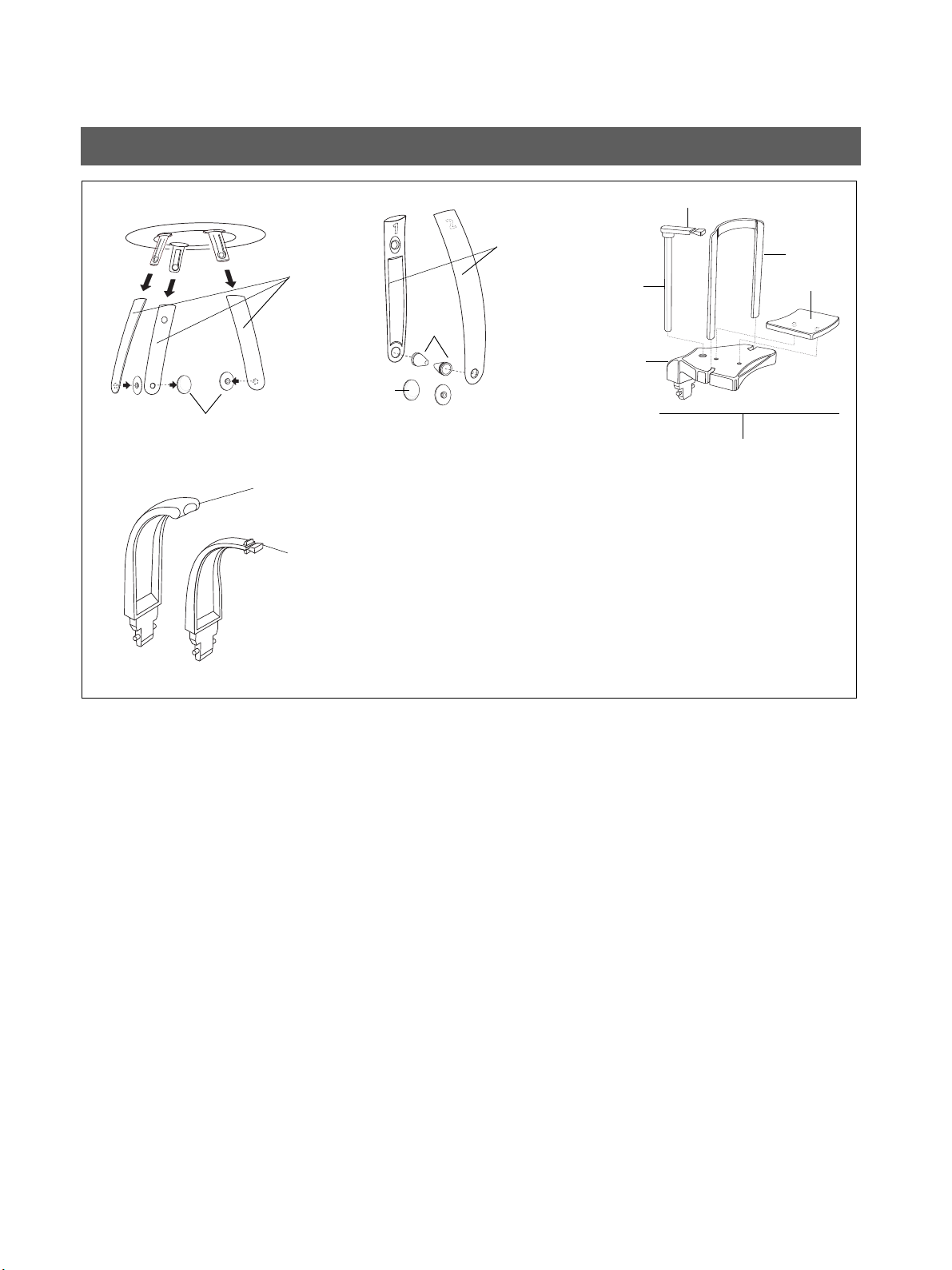
Accessories: Panoramic X-ray unit
1. Forehead (1x) and temple supports (2x)
2. Buttons (2x)
3. Temporomandibular joint supports 1 (1x) and 2 (1x)
4. Ear holders (4x)
5. Buttons TMJ (2x)
6. Chin rest accessories (1x)
– Bite block (5x)
– Bite block fixation (1x)
–Bar (1x)
– Chin pad (1x)
– Chin rest (1x)
7. Contact segment standard yellow (1x)
8. Bite block standard yellow (1x)
8.
12.
10.
11.
13.
7.
9.
Bar
Bite block
Bite block fixation
14.
Chin rest
Chin pad
Sirona Dental Systems GmbH 2 Delivery and transport
Installation Instructions ORTHOPHOS XG 3 2.1 Delivery
60 51 416 D 3352
D 3352.031.03.18.02
17
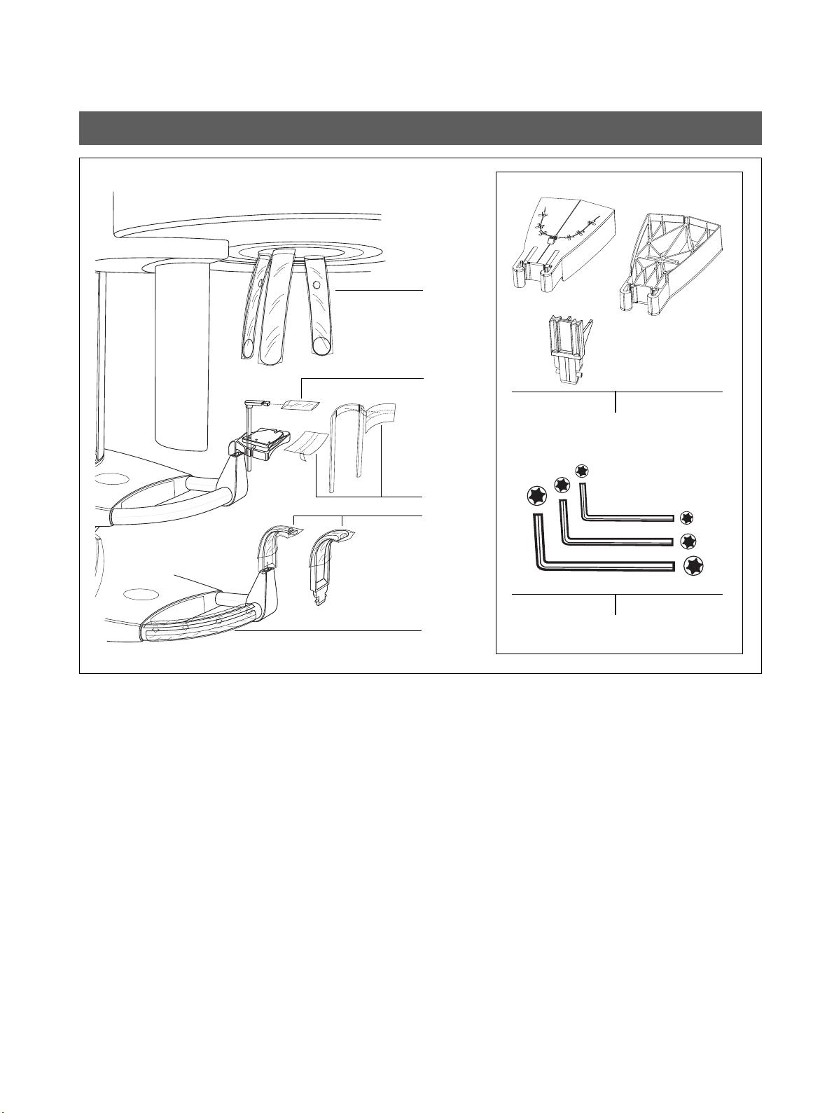
Hygienic protection
Hygienic protective sleeves for...
9. Forehead and temple supports (500x)
10. Bite block (500x)
11. Chin rest and bar (100x)
12. Bite blocks and contact segments (500x)
13. XG hygienic handle (100x)
Adjustment set: Panoramic X-ray unit
14. Panoramic needle phantom
15. Set of Torx offset screwdrivers
19.
18.
17.
20.
21.
22.
23.
Top sideBottom side
2 Delivery and transport Sirona Dental Systems GmbH
2.2 Transport to the installation site Installation Instructions ORTHOPHOS XG 3
60 51 416 D 3352
18 D 3352.031.03.18.02
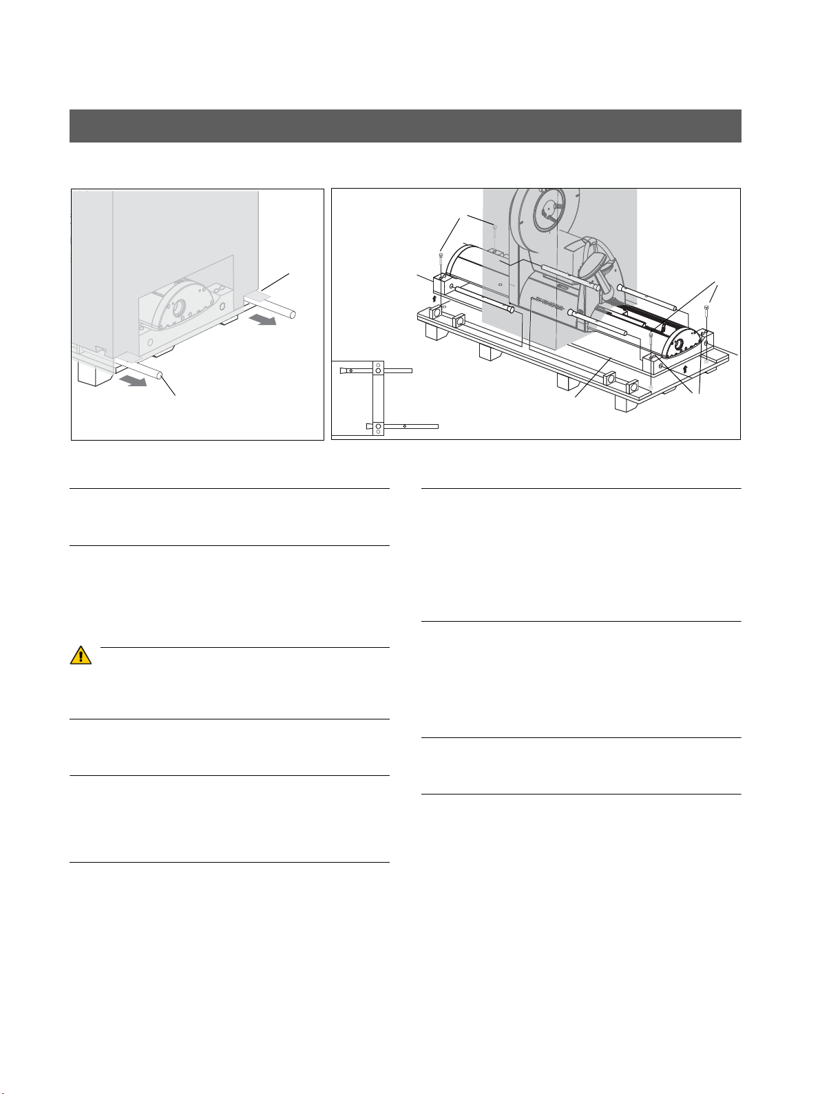
NOTICE
If possible leave the packaging attached to the unit during
transport in order to protect it against damage.
1. Transport with packaging attached (normal case)
– Open the surrounding packaging at the tabs pro
-
vided for that purpose (A), pull out the carrying
handles (B), and transport the unit to the installa
-
tion site.
WARNING
When in transport position, the unit has a very high
center of gravity. Take care that the unit does not tip
over during transport.
2. Transport without pallet (exception)
IMPORTANT
If the pallet is too wide for transport to the installation site,
you may unscrew the pallet from wooden support C and
transport the unit by means of the wooden supports without
the pallet.
To do this, proceed as follows:
– Remove the surrounding packaging, the two card
-
board boxes, as well as the two lateral styrofoam
parts.
– Loosen the four screws D.
NOTICE
The center styrofoam part should remain attached to the
unit for protection. If this is not possible, SIRONA recom
-
mends securing the tube assembly in its position with the
supplied strap prior to any further transport
(see the label on the styrofoam packaging)!
Tighten the strap only loosely. Do not stretch!
– Pull the carrying handles B out of their holders and
insert them through the drillings of the wooden sup
-
port C from the back.
– Insert screws D through the drillings E into the drill
-
ings of the carrying handles to attach them firmly.
Long or short.
IMPORTANT
The carrying handles have rims which prevent them from
slipping out of the holes.
2.2 Transport to the installation site
1. 2.
A
B
short
long
C
D
D
E

ORTHOPHOS XG 3
60 51 416 D 3352
D 3352.031.03.18.02
19
3 Installation: Panoramic X-ray unit
3 Installation: Panoramic X-ray unit Sirona Dental Systems GmbH
3.1 Installation material Installation Instructions ORTHOPHOS XG 3
60 51 416 D 3352
20 D 3352.031.03.18.02
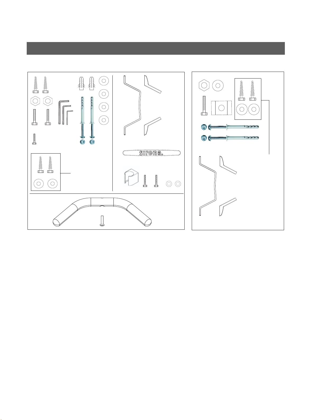
Standard version
(see Section 3.3)
1. Wall/floor mounting
– Hexagon wood screws 8x80 (5/16x3"): 4 pc.
– Plastic wall plug S10: 2 pc.
– Screw M8x30: 2 pc.
–Washer δια. 8.4: 6 pc.
– Nut M8: 2 pc.
– Screw M4x10: 3 pc.
–Washer δια. 4.3: 2 pc.
– Mounting kit δια. 10 SXR: 2 pc.
– Torx offset screwdrivers TX10, TX20, TX25: resp. 1
pc.
– Offset Allen key (size 6):
1 pc.
– Wall holder: 1 pc.
– Cover for wall holder: 2 pc.
– Intermediate piece: 1 pc.
– Release button holder: 1 pc.
– Handle: 1 pc.
– Screw (for handle) M6x25: 1 pc.
Option 1: with second wall holder
(see Section 3.3)
2. Additional wall holder (for bottom wall mounting)
– Wall holder: 1 pc.
– Wood screws 8x80 (5/16x3"): 2 pc.
–Washer δια. 8.4: 3 pc.
– Hexagon head screw M8x50: 1 pc.
– Nut M8: 1 pc.
– Mounting kit δια. 10 SXR: 2 pc.
– Profile clamp: 1 pc.
– Cover for wall holder: 2 pc.
3.1 Installation material
1. 2.
for installation
on wooden stud
frame
for installation
on wooden stud
frame

Sirona Dental Systems GmbH 3 Installation: Panoramic X-ray unit
Installation Instructions ORTHOPHOS XG 3 3.1 Installation material
60 51 416 D 3352
D 3352.031.03.18.02
21
Option 2: Floor stand installation
(see Section 3.4)
3. Floor stand installation
– Floor stand
– Floor stand covers
– Wood screws 10x160 (3/8x6"): 5 pc.
– Plastic wall plug S12: 5 pc.
– Screw EM8x60: 2 pc.
– Screw M8x80: 2 pc.
– Washer δια. 8.4: 2 pc.
– Nut M8: 2 pc.
– Screw M10x50: 1 pc.
– Profile clamp: 1 pc.
– Screw M5x12: 1 pc.
– Washer δια. 10.5: 13 pc.
– Nut M10: 4 pc.
– Spring steel clamp: 8 pc.
– Screw M10x25: 4 pc.
– Wood screw M10x80 (3/8x3): 5 pc.
– Mounting kit δια. 10 SXR: 2 pc.
3.
Option 2
Mounting hardware
Floor stand
Covers
Floor stand
Cover
Slide
3 Installation: Panoramic X-ray unit Sirona Dental Systems GmbH
3.2 Required tools Installation Instructions ORTHOPHOS XG 3
60 51 416 D 3352
22 D 3352.031.03.18.02
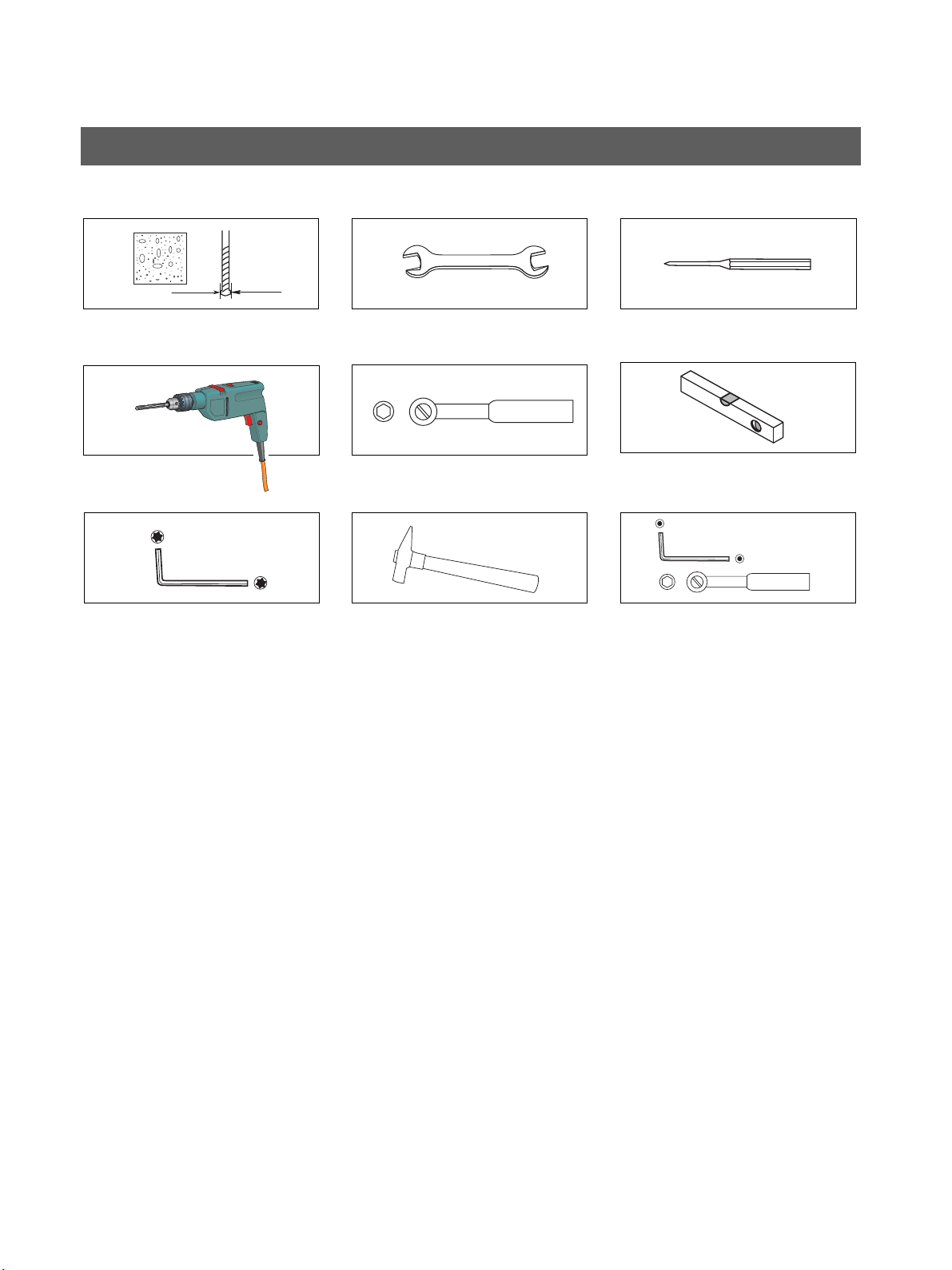
1. Masonry drill
– Δια.10mm (3/8“)
2. Impact drill or percussion drill
3. Torx offset screwdriver *
–TX10
–TX20
–TX25
4. Open-end wrench
– 13 mm A/F
5. Socket wrench
– Wrench insert 13
6. Hammer
7. Center punch
8. Spirit level
9. Additional requirements for installation with floor stand:
– Masonry drill δια.12mm (1/2“)
– Allen key 6 mm
– Socket wrench and extension
Wrench insert 17
* included in the scope of supply
Required measuring instruments
• Multimeter or ammeter (battery-operated)
• Test unit for device leakage current measurement,
e.g. Bender tester or line-frequency, high-resistance
measurement voltage source (isolation transformer)
and measuring circuit (MD) that meets the require
-
ments of IEC 60 601-1.
• Power source for protective ground wire test
Technical data:
– No-load voltage of at least 4 V - maximally 24V
– Short-circuit current at least 0.2A
3.2 Required tools
1.
2.
3.
7.4.
5.
6.
8.
9.
Sirona Dental Systems GmbH 3 Installation: Panoramic X-ray unit
Installation Instructions ORTHOPHOS XG 3 3.3 Wall mounting (standard/option 1)
60 51 416 D 3352
D 3352.031.03.18.02
23
3.3 Wall mounting (standard/option 1)
1.
2.
3 Installation: Panoramic X-ray unit Sirona Dental Systems GmbH
3.3 Wall mounting (standard/option 1) Installation Instructions ORTHOPHOS XG 3
60 51 416 D 3352
24 D 3352.031.03.18.02
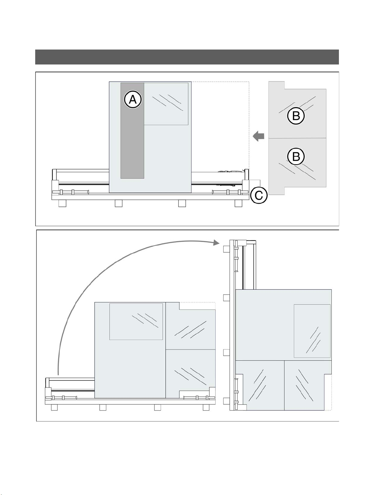
• Remove profile cover A.
1. Position the two installation aids B at the foot C of the
device and secure their position with adhesive tape.
CAUTION! The installation aids must be placed on
top of each other in such a way that their openings
lie on top of each other
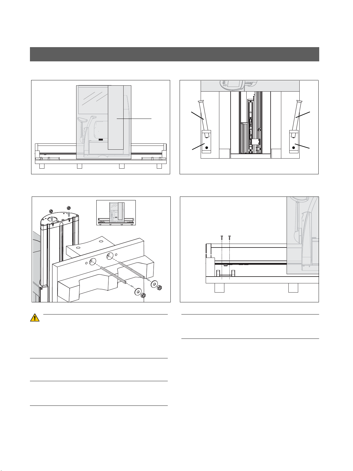
2. Set up the unit. To do this, tilt the transport pallet up
-
right.
IMPORTANT
If you have transported the unit on the wooden support with
-
out a pallet, set the unit upright with the wooden support.
You can also use the lateral styrofoam packaging as a sup
-
port with this variation.
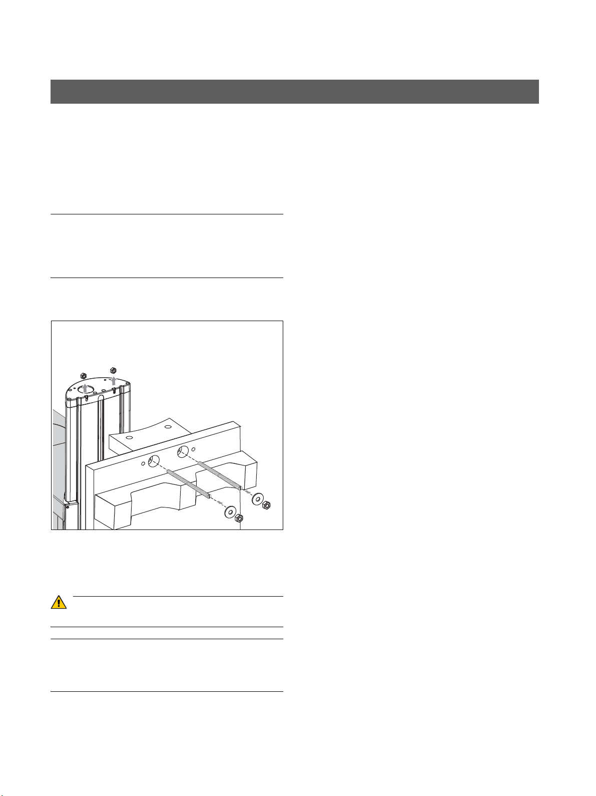
3. Loosen the nuts B (with washers) on both sides of the
pallet (or the wooden support). Take off the pallet (or
the wooden support).
Remove the threaded bolts C.
CAUTION
Remove the lower bolts first, followed by the upper bolts.
IMPORTANT
The nuts D on the unit may remain inside the unit when the
threaded rods are removed. Remove the upper nuts. The
lower nuts may remain in the unit.
3.
B
C
D
Sirona Dental Systems GmbH 3 Installation: Panoramic X-ray unit
Installation Instructions ORTHOPHOS XG 3 3.3 Wall mounting (standard/option 1)
60 51 416 D 3352
D 3352.031.03.18.02
25
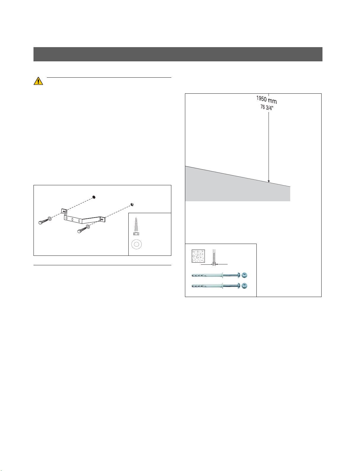
CAUTION
If the setup site for the unit is carpeted, the carpeting must
be removed.
Wall plugs! Each wall plug must withstand an extraction
force of 700 N.
The wall construction must be suitable for installation of the
unit (see "On-site installation, dimensions, technical data")
In case of mounting on weight-bearing wooden con
-
structions:
Use the enclosed wood screws and washers from the
mounting kit for mounting the unit on weight-bearing wood
structures.
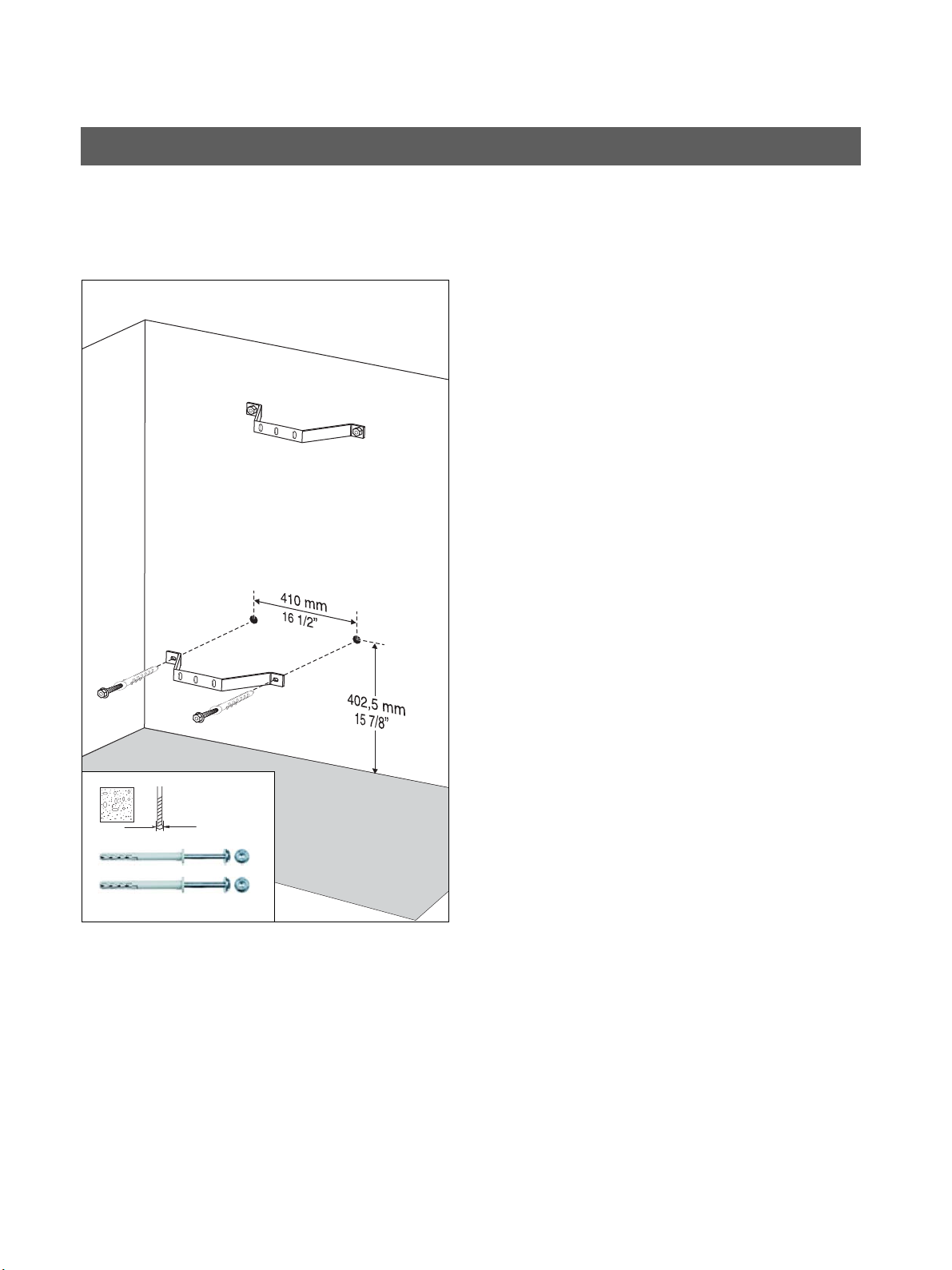
4. Mount the upper wall holder.
2x 8x80
2x δια. 8.4
4.
Δια. 3/8″
Δια.
10 mm
3 Installation: Panoramic X-ray unit Sirona Dental Systems GmbH
3.3 Wall mounting (standard/option 1) Installation Instructions ORTHOPHOS XG 3
60 51 416 D 3352
26 D 3352.031.03.18.02
Only with second wall holder (option 1):
5. Mount the lower wall holder.
5.
Δια. 3/8″
Δια.
10 mm
Sirona Dental Systems GmbH 3 Installation: Panoramic X-ray unit
Installation Instructions ORTHOPHOS XG 3 3.3 Wall mounting (standard/option 1)
60 51 416 D 3352
D 3352.031.03.18.02
27
• Move the panoramic X-ray unit into its installation posi
-
tion at the wall. Hold the unit laterally at the styrofoam
packaging to do this.
NOTICE
SIRONA recommends leaving the styrofoam packaging on
the unit during the entire installation procedure!
If due to on-site conditions it is unavoidable to remove the
styrofoam packaging already at this point, you may move
the unit by carefully grasping the bite block bar and the
stand.
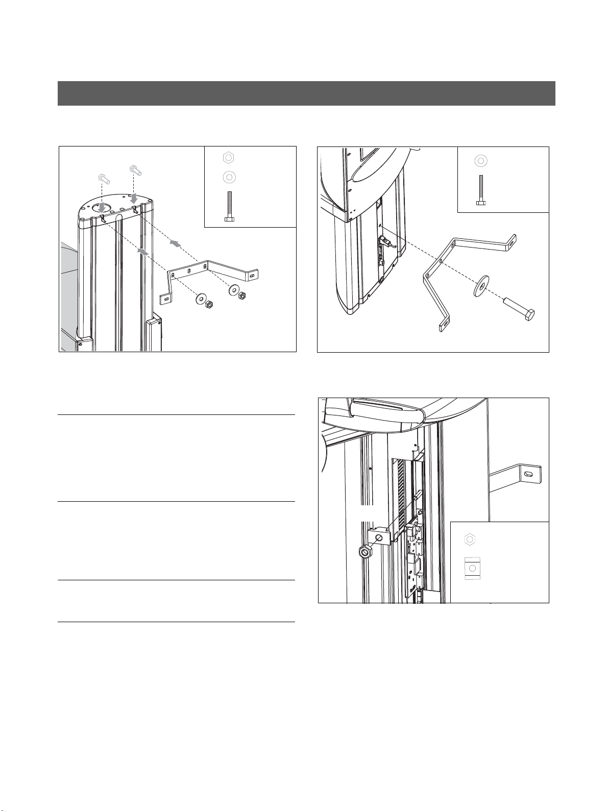
6. Fasten the panoramic X-ray unit to the upper wall hold
-
er.
– Insert the screws E into the groove.
– Screw the panoramic X-ray unit firmly onto the wall
holder using the washers and nuts F.
IMPORTANT
The wall holder must be flush with the upper edge of the
unit.
7. Insert screw G through washer H and then through
the wall holder and into the stand from the rear.
8. Fit profile clamp J onto screw G from the other (front)
side and screw nut K onto the screw.
Tighten nut K firmly.
6.
E
F
2x M 8x30
2x δια. 8.4
2x M 8
7.
1x M 8x50
1x δια. 8.4
G
H
E
F
G
H
8.
D
1x M 8
J
Profile clamp
1x
K
K
J
3 Installation: Panoramic X-ray unit Sirona Dental Systems GmbH
3.3 Wall mounting (standard/option 1) Installation Instructions ORTHOPHOS XG 3
60 51 416 D 3352
28 D 3352.031.03.18.02
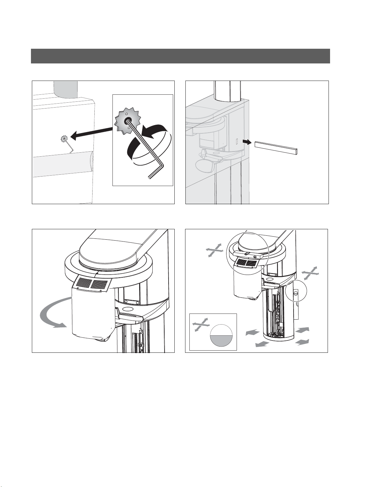
9. Remove the transport safety device (A) prior to unit
startup.
10. Pull the wooden board L out of the styrofoam packag
-
ing and remove all styrofoam packaging.
11. Rotate the X-ray tube assembly counterclockwise to
the front side of the unit.
12. Level the unit by moving the unit base in both directions
while measuring with the spirit level.
– Align the stand first by placing the spirit level
against the side and rear of the stand
➊ .
– Then align the ring with the spirit level in both
directions by placing the spirit level on the ring
➋ .
12.
➊
➋
9. 10.
L
A
Sirona Dental Systems GmbH 3 Installation: Panoramic X-ray unit
Installation Instructions ORTHOPHOS XG 3 3.3 Wall mounting (standard/option 1)
60 51 416 D 3352
D 3352.031.03.18.02
29
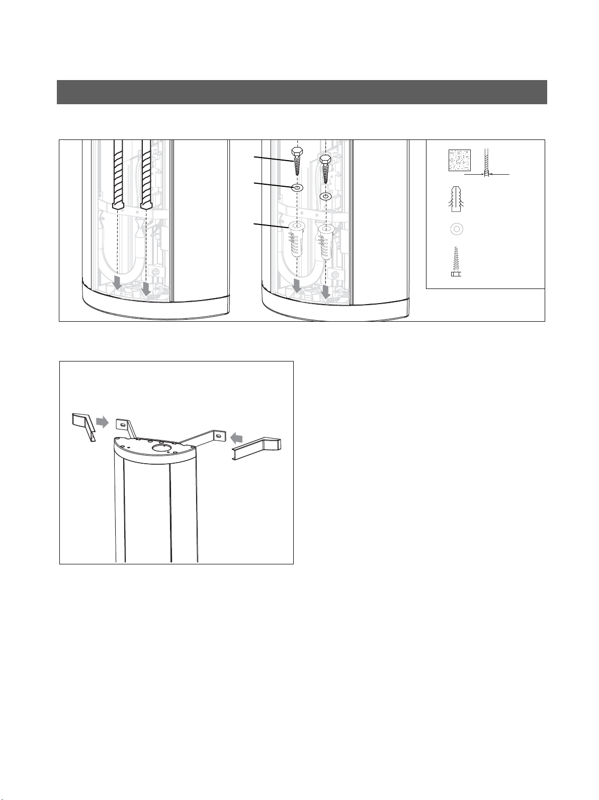
13. Drill through the recesses of the stand into the floor. In
-
sert wall plug M, and check again that the stand is
aligned correctly (see step 10).
Screw the stand to the floor with the two wood screws N
and the washers O.
14. Attach the covers of the wall holder(s).
14.
2x S 10
Δια. 10 mm
2x 8x80
2x δια. 8.4
N
M
N
O
M
O
13.
3 Installation: Panoramic X-ray unit Sirona Dental Systems GmbH
3.4 Installing the floor stand (option 2) Installation Instructions ORTHOPHOS XG 3
60 51 416 D 3352
30 D 3352.031.03.18.02
CAUTION
For installation with the floor stand, the unit remains lying on
the pallet until the floor stand has been completely assem
-
bled. Only then may the unit be installed. For enhanced rep
-
resentation, some of the following drawings are shown in
the standing state.
1. Remove the surrounding packaging, the two lateral sty
-
rofoam parts and profile cover A.
NOTICE
The center styrofoam part should remain attached to the
unit for protection.
2. Loosen the nuts B (with washers) on both sides of the
pallet (or the wooden support). Take off the pallet (or
the wooden support). Remove the threaded bolt C.
IMPORTANT
The nuts D on the unit may remain inside the unit when the
threaded rods are removed. Remove the nuts.
3. Remove the carrying handles E on the lower side of the
pallet from the holders F.
4. Loosen screws G and remove the holders F.
3.4 Installing the floor stand (option 2)
1.
A
B
C
C
B
C
D
2. 4.
E
G
F
Must be dis
-
mantled ly
-
ing on its
3.
E
F
F
 Loading...