


Orthophos XG3D
Table of contents
 Loading...
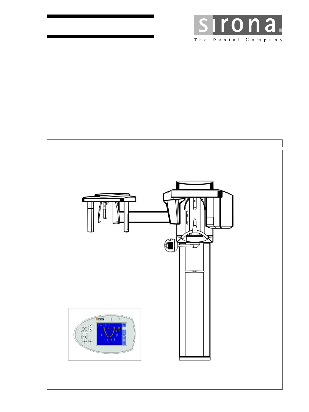
kÉï=~ë=çÑW=
NMKOMNR
loqelmelp=ud=Pa=L=`ÉéÜ
fåëí~ää~íáçå=j~åì~ä
Cover page
bеЦдблЬ
bеЦдблЬ
=


Sirona Dental Systems GmbH Table of contents
Installation Manual ORTHOPHOS XG 3D / Ceph
Table of contents
1
2
About these Installation Instructions......................................................................... 9
1.1 Scope ............................................................................................................ 9
1.2 Other documentation required ...................................................................... 9
1.3 Structure of the document............................................................................. 10
1.3.1 Identification of the danger levels..................................................... 10
1.3.2 Formats and symbols used.............................................................. 10
Safety instructions .................................................................................................... 11
2.1 Information on the unit .................................................................................. 11
2.2 Fixed connection ........................................................................................... 11
2.3 Ventilation slots ............................................................................................. 11
2.4 Condensation ................................................................................................ 11
2.5 Qualifications of service personnel ............................................................... 12
2.6 Switching the unit on ..................................................................................... 12
2.7 Radiation protection ...................................................................................... 12
2.8 Laser light localizer ....................................................................................... 12
2.9 Modifications to the unit ................................................................................ 12
2.10 Transport safety devices ............................................................................... 12
bеЦдблЬ
2.11 Electromagnetic compatibility........................................................................ 13
2.12 Electrostatic discharge .................................................................................. 13
3
4
Unit description......................................................................................................... 14
3.1 System versions............................................................................................ 14
3.2 Dimensions/Space requirements .................................................................. 15
3.2.1 Front view......................................................................................... 15
3.2.2 Top view........................................................................................... 16
3.2.3 Top view of floor stand ..................................................................... 17
3.3 Mounting options........................................................................................... 18
3.4 Installation versions....................................................................................... 19
Delivery and transport .............................................................................................. 20
4.1 Delivery ......................................................................................................... 20
4.1.1 ORTHOPHOS XG 3D ...................................................................... 22
4.1.1.1 Accessories ....................................................................... 24
4.1.1.2 Hygienic protection............................................................ 27
4.1.1.3 3D module ......................................................................... 28
63 03 452 D3352
D3352.031.05.08.02 10.2015
3

Table of contents Sirona Dental Systems GmbH
Installation Manual ORTHOPHOS XG 3D / Ceph
4.1.2 Ceph arm ......................................................................................... 29
4.1.2.1 Accessories ....................................................................... 30
4.1.2.2 Hygienic protection............................................................ 30
4.1.3 Adjustment sets................................................................................ 31
4.2 Transport to the installation site .................................................................... 33
4.2.1 ORTHOPHOS.................................................................................. 33
4.2.1.1 Transport with packaging attached (normal case) ............ 33
4.2.1.2 Transport without pallet (exception) .................................. 34
4.2.2 3D module........................................................................................ 35
4.2.3 Ceph arm ......................................................................................... 35
5
6
Installation: X-ray unit............................................................................................... 36
5.1 Installation material ....................................................................................... 36
5.1.1 Standard version .............................................................................. 36
5.1.2 Option 1: with second wall holder .................................................... 38
5.1.3 Option 2: Floor stand installation...................................................... 39
5.2 Tools, materials, and measurement tools you will need ............................... 41
5.2.1 Tools and materials.......................................................................... 41
5.2.2 Measurement tools........................................................................... 42
5.3 Wall mounting (standard and option 1) ......................................................... 43
5.4 Installing the floor stand (option 2) ................................................................ 49
5.5 Remove the transport safety device.............................................................. 56
5.6 Installing the release button holder ............................................................... 56
Installation: Combisensor ......................................................................................... 57
6.1 Installation material ....................................................................................... 57
6.2 Required tools ............................................................................................... 57
6.3 Installing the 3D module................................................................................ 58
6.4 Inserting the 2D sensor ................................................................................. 62
6.5 Final installation work.................................................................................... 63
7
Installation: Remote control...................................................................................... 64
7.1 Installation material ....................................................................................... 64
7.2 Required tools ............................................................................................... 64
7.3 Installation ..................................................................................................... 65
7.4 Connecting the control cables (REMOTE) .................................................... 68
7.4.1 Installation version 1: Without coiled cable ...................................... 68
7.4.2 Installation version 2: With spiral cable ............................................ 69
7.5 Connecting the X-ray warning lamp .............................................................. 70
7.6 Final installation work.................................................................................... 71
7.7 Connecting a door contact switch ................................................................. 72
63 03 452 D3352
4 D3352.031.05.08.02 10.2015

Sirona Dental Systems GmbH Table of contents
Installation Manual ORTHOPHOS XG 3D / Ceph
8
9
10
Electrical connection ................................................................................................ 73
8.1 Connecting the control cables....................................................................... 73
8.2 Connecting the line voltage........................................................................... 74
8.2.1 Connecting the unit .......................................................................... 74
8.2.2 Connecting the media converter ...................................................... 75
Safety checks ........................................................................................................... 76
9.1 Checking the protective ground wires ........................................................... 76
9.2 Checking the device leakage current ............................................................ 80
Installation: Ceph arm .............................................................................................. 81
10.1 Installation material ....................................................................................... 81
10.2 Required tools ............................................................................................... 82
10.3 Installation ..................................................................................................... 83
10.3.1 Ceph arm mounted on left-hand side............................................... 83
10.3.2 Ceph arm mounted on right-hand side............................................. 86
10.3.3 Installing the secondary diaphragm ................................................. 90
10.4 Connecting control cables............................................................................. 91
10.4.1 Running the cables for the left-hand arm ......................................... 92
10.4.2 Running the cables for the right-hand arm....................................... 93
bеЦдблЬ
11
10.5 Final installation work.................................................................................... 94
Initial startup............................................................................................................. 96
11.1 Attaching the covers...................................................................................... 96
11.2 Inserting the forehead and temple supports.................................................. 97
11.3 Inserting the ceph sensor (for ceph versions) ............................................... 98
11.4 Installing the IT package ............................................................................... 99
11.5 Switching the unit on ..................................................................................... 100
11.5.1 Factory setting after switch-on ......................................................... 101
11.6 Performing a mechanical function test .......................................................... 102
11.7 Setting up the X-ray component via the SIXABCon program ....................... 104
11.7.1 Starting SIXABCon........................................................................... 105
11.7.2 Selecting an X-ray component ......................................................... 108
11.7.3 Approval of the X-ray component..................................................... 114
11.8 Checking the data paths ............................................................................... 116
11.8.1 Creating 2D test images................................................................... 116
11.8.2 Creating a 3D test image ................................................................. 118
11.9 Checking the unit configuration..................................................................... 120
63 03 452 D3352
D3352.031.05.08.02 10.2015
5

Table of contents Sirona Dental Systems GmbH
Installation Manual ORTHOPHOS XG 3D / Ceph
11.10 Service routines for startup ........................................................................... 121
11.10.1 Service menu and service routines .................................................. 121
11.10.1.1Displays and symbols in the service menu ....................... 121
11.10.2 Basic operating procedures in the service menu ............................. 123
11.10.2.1Activating the service menu .............................................. 123
11.10.2.2Selecting service routines and test steps.......................... 125
11.10.2.3Select parameters ............................................................. 128
11.10.2.4Saving parameters ............................................................ 129
11.10.2.5Exiting the test step and service routine ........................... 129
11.10.3 S017: Configuration service ............................................................. 130
11.10.3.1S017: Test step 2 .............................................................. 130
11.10.3.2S017: Test step 3 .............................................................. 134
11.10.3.3S017: Test step 4 .............................................................. 135
11.10.3.4S017: Test step 5 .............................................................. 137
11.10.3.5S017: Test step 6 .............................................................. 138
11.10.3.6S017: Test step 8 .............................................................. 139
11.10.3.7S017: Test step 9 .............................................................. 140
11.10.3.8S017: Test step 12 ............................................................ 141
11.10.3.9S017: Test step 13 ............................................................ 142
11.10.3.10S017: Test step 14 .......................................................... 143
11.10.3.11S017: Test step 15 .......................................................... 145
11.10.3.12S017: Test step 17 .......................................................... 146
11.10.3.13S017: Test step 18 (occlusal bite block only).................. 149
11.10.3.14S017: Test step 21 .......................................................... 151
11.10.4 S018: Service for height adjustment ................................................ 152
11.10.4.1S018: Test step 2 .............................................................. 153
11.10.4.2S018: Test step 3 .............................................................. 154
11.10.4.3S018: Test step 4 .............................................................. 155
11.10.4.4S018: Test step 5 .............................................................. 156
11.10.4.5S018: Test step 6 .............................................................. 157
11.10.4.6S018: Test step 7 (occlusal bite block only)...................... 158
11.10.4.7S018: Test step 8 (occlusal bite block only)...................... 160
11.10.4.8S018: Test step 9 (occlusal bite block only)...................... 162
11.10.4.9S018: Test step 10 (occlusal bite block only).................... 164
11.10.5 S037: Network service ..................................................................... 165
11.10.5.1S037: Test step 1 .............................................................. 165
11.10.5.2S037: Test step 2 .............................................................. 167
11.10.5.3S037: Test step 3 .............................................................. 169
11.10.5.4S037: Test step 4 .............................................................. 170
11.11 Using demo mode – operation without radiation release .............................. 173
11.11.1 Switching on demo mode................................................................. 173
11.11.2 Switching off demo mode................................................................. 174
11.11.3 Important information for repacking and transport ........................... 175
6 D3352.031.05.08.02 10.2015
63 03 452 D3352

Sirona Dental Systems GmbH Table of contents
Installation Manual ORTHOPHOS XG 3D / Ceph
12
13
Startup, measurements and tests (for USA/Canada only) ....................................... 178
12.1 Safety ............................................................................................................ 178
12.2 Operation notes............................................................................................. 179
12.3 Auxiliary devices required ............................................................................. 180
12.4 Checking the power supply connection......................................................... 181
12.5 Testing the tube voltage (tube assembly 2.0) ............................................... 183
12.6 Checking the radiation time........................................................................... 184
12.7 Checking the tube current ............................................................................. 185
12.8 Checking the laser light localizers................................................................. 189
Adjusting and calibrating the unit ............................................................................. 193
13.1 General information about unit adjustment and calibration........................... 194
13.1.1 Displays and help messages during adjustment/calibration ............ 195
13.1.2 "Adjustment/Calibration" menu......................................................... 196
13.1.2.1 Calling the "Adjustment/Calibration" menu........................ 196
13.1.2.2 Menu structure .................................................................. 197
13.1.3 Enabling exposure readiness........................................................... 206
13.1.4 Taking an exposure.......................................................................... 206
13.1.5 Save values...................................................................................... 206
13.1.6 Test phantoms for adjustment and calibration ................................. 207
13.1.6.1 OP XG needle phantom for panoramic adjustment........... 207
13.1.6.2 OP XG 3D ceph adjustment phantom for the adjustment
of the cephalometer
13.1.6.3 Geometry phantom for volume calibration ........................ 210
209
bеЦдблЬ
13.2 Adjustment and calibration via the "Unit adjustment/calibration" menu ........ 212
13.2.1 2D adjustment .................................................................................. 212
63 03 452 D3352
D3352.031.05.08.02 10.2015
13.2.1.1 Pan sensor adjustment...................................................... 212
13.2.1.2 Pan diaphragm .................................................................. 216
13.2.1.3 Pan symmetry ................................................................... 220
13.2.1.4 Ceph - Primary diaphragm ................................................ 224
13.2.1.5 Ceph - Fixed point of rotation ............................................ 228
13.2.1.6 Ceph - Main X-ray beam direction..................................... 234
13.2.1.7 Ceph - Fixed point of rotation for QuickShot ..................... 238
13.2.1.8 Ear plug alignment ............................................................ 243
7

Table of contents Sirona Dental Systems GmbH
Installation Manual ORTHOPHOS XG 3D / Ceph
13.2.2 3D adjustment/calibration................................................................. 248
13.2.2.1 Sensor ............................................................................... 248
13.2.2.2 Aperture............................................................................. 250
13.2.2.3 Shading ............................................................................. 252
13.2.2.4 Shading (5x5) .................................................................... 253
13.2.2.5 Geometry........................................................................... 254
13.2.2.6 Dosimetry .......................................................................... 255
13.2.3 Saving adjustment/calibration data .................................................. 256
13.2.4 Resetting adjustment/calibration ...................................................... 257
13.3 Checking and adjusting the touchscreen ...................................................... 259
13.4 Mechanical adjustments................................................................................ 261
13.4.1 Mechanical adjustment: Ceph secondary diaphragm ...................... 261
14
Final work ................................................................................................................. 263
14.1 Attaching the profile cover............................................................................. 263
14.2 Calling "Extended Details"............................................................................. 264
14.3 Filling in the certificate of conformity ............................................................. 266
14.4 Unit handover................................................................................................ 267
8 D3352.031.05.08.02 10.2015
63 03 452 D3352

Sirona Dental Systems GmbH 1About these Installation Instructions
Installation Manual ORTHOPHOS XG 3D / Ceph 1.1Scope
About these Installation Instructions
1
1.1
1.2
Scope
Scope of installation instr uctions: XG 3D
These installation instructions describe the installation of the
ORTHOPHOS XG 3D/Ceph digital volume tomograph. They are intended
for use exclusively by trained and authorized distributors and service
technicians.
Other documentation required
In addition to these installation instructions you will require the following
documentation:
XG 3D / 3D ready wiring diagrams
Wiring diagrams
● ORTHOPHOS XG 3D / 3D
Installation GALILEOS/XG 3D
Installation Instructions
● GALILEOS / ORTHOPHOS XG 3D Software installation:
REF 61 42 389
● GALAXIS Operator's Manual: REF 61 23 488
● SIDEXIS XG Digital Radiography Installation Instructions:
REF 59 67 356
Operation with SIDEXIS 4
IMPORTANT
Operation with SIDEXIS 4
ready
Wiring References: REF 63 03 494
bеЦдблЬ
When operating the unit with SIDEXIS 4, please refer also to the
document
Service Manual: XG 3D
"Supplements for operation with SIDEXIS 4"
(REF 6524776).
Service manual
● ORTHOPHOS XG 3D Service Manual: REF 63 03 510
DVD text
Current Service Documentation, such as the Service Manual, can be
downloaded from the Sirona dealer website.
63 03 452 D3352
D3352.031.05.08.02 10.2015
9
1About these Installation Instructions Sirona Dental Systems GmbH
1.3Structure of the document Installation Manual ORTHOPHOS XG 3D / Ceph
1.3
Structure of the document
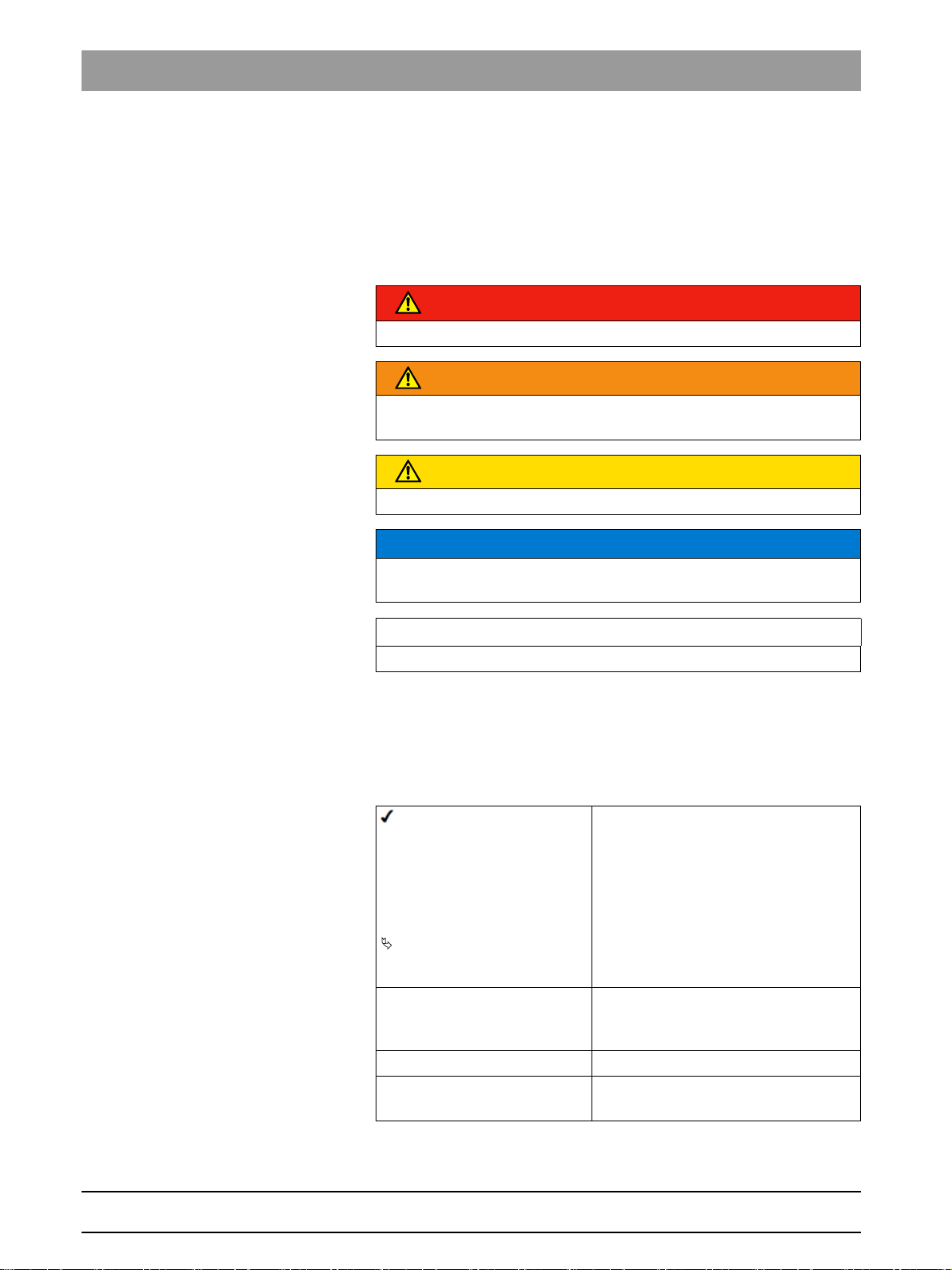
1.3.1 Identification of the danger levels
To prevent personal injury and material damage, please observe the
warning and safety information provided in the present operating
instructions. Such information is highlighted as follows:
DANGER
An imminent danger that could result in serious bodily injury or death.
WARNING
A possibly dangerous situation that could result in serious bodily injury
or death.
CAUTION
A possibly dangerous situation that could result in slight bodily injury.
NOTICE
A possibly harmful situation which could lead to damage of the product
or an object in its environment.
IMPORTANT
Application instructions and other important information.
Tip: Information on making work easier.
1.3.2 Formats and symbols used
The formats and symbols used in this document have the following
meaning:
Prerequisite
1. First action step
2. Second action step
or
➢ Alternative action
Result
➢ Individual action step
See "Formats and symbols
used [ → 10]"
● List Designates a list.
"Command / menu item" Indicates commands, menu items or
Requests you to do something.
Identifies a reference to another text
passage and specifies its page
number.
quotations.
10 D3352.031.05.08.02 10.2015
63 03 452 D3352
Sirona Dental Systems GmbH 2Safety instructions
Installation Manual ORTHOPHOS XG 3D / Ceph 2.1Information on the unit
Safety instructions
2
Accompanying documents
Electrostatic discharge (ESD)
Identification of single use devices
2.1
Information on the unit
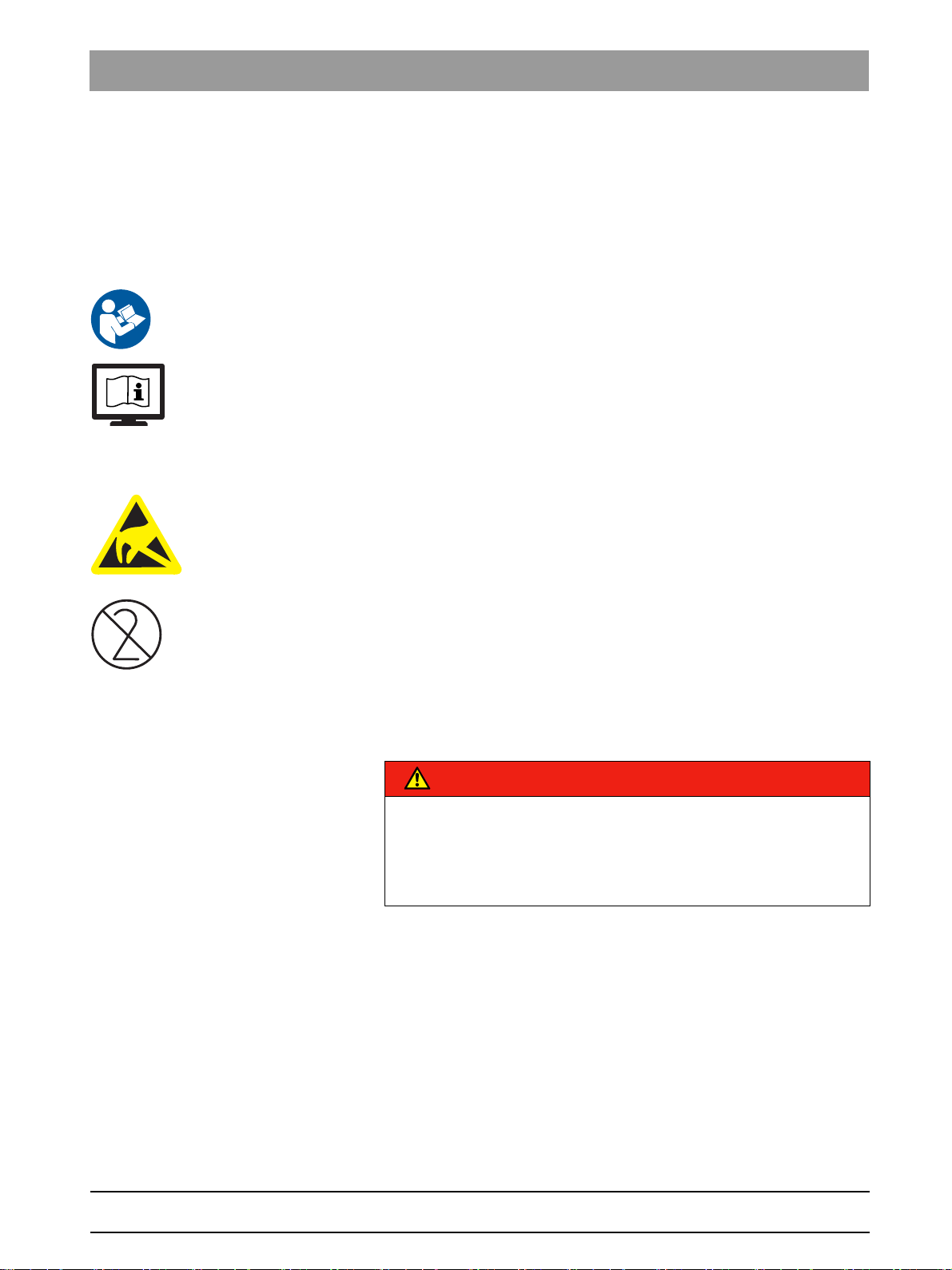
The following symbols are applied to the unit:
Accompanying document s
This symbol is affixed next to the unit rating plate.
Meaning: When operating the unit, observe the operating instructions.
This symbol is affixed on the unit rating plate.
Meaning: The accompanying documents are available on the homepage
of Sirona.
Connector pins or sockets bearing ESD warning labels must not be
touched or interconnected without ESD protective measures. See also
"Electrostatic Discharge" and "Electromagnetic Compatibility" [ → 13].
Single use hygienic prote ctive sleeves
Prior to each exposure, the hygienic protective sleeves (single use
devices) must be fitted.
Single use devices are identified with the symbol shown on the left. They
must be disposed of immediately after use. Do not use single use devices
more than once.
bеЦдблЬ
2.2
2.3
2.4
Fixed connection
DANGER
Potentially lethal shock hazard!
Fixed connection!
Installing a mains plug instead of the specified fixed connection infringes
international medical regulatory actions and is prohibited. In case of
error, this puts patients, users, and other parties seriously at risk.
Ventilation slots
Ventilation slots
Never cover the ventilation slots on the unit under any circumstances,
since this may obstruct air circulation. This can cause the unit to overheat.
Condensation
Safety information for co ndensation: Service engineer
Extreme fluctuations of temperature may cause condensation inside the
unit. Do not switch the unit on before it has reached normal room
temperature. See also Technical Data.
63 03 452 D3352
D3352.031.05.08.02 10.2015
11
2Safety instructions Sirona Dental Systems GmbH
2.5Qualifications of service personnel Installation Manual ORTHOPHOS XG 3D / Ceph
2.5
2.6
2.7
2.8
Qualifications of service personnel
Installation and startup may be carried out only by personnel specifically
authorized by Sirona.
Switching the unit on
Safety information for switching o n the unit: Service engineer
Due to the risk of injury caused by malfunction, no person may be
positioned in the unit when it is switched on.
Radiation protection
Safety information for radiation protection: Service engineer
The valid radiation protection regulations and measures must be
observed. The statutory radiation protection equipment must be used.
During an exposure, the service engineer should move as far away from
the X-ray tube assembly as the coiled cable of the manual release
permits.
With the exception of the service engineer, no other persons are allowed
to stay in the room during an exposure.
In case of malfunctions, cancel the exposure immediately by letting go of
the exposure release button.
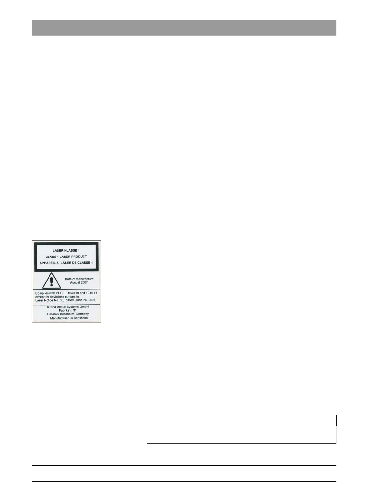
Laser light localizer
2.9
2.10
Safety information for light loca lizer: Service engineer
The system incorporates Class 1 laser products.
A minimum distance of 10 cm (4") is required between the eye and the
laser. Do not stare into the beam.
Do not use the system with any other lasers, and do not make any
changes to settings or processes that are not described in these
operating instructions. This may lead to a dangerous exposure to
radiation.
Modifications to the unit
Modifications to this unit which might affect the safety of the system
owner, patients or other persons are prohibited by law!
For reasons of product safety, this product may be operated only with
original Sirona accessories or third-party accessories expressly approved
by Sirona. The user is responsible for any damage resulting from the use
of non-approved accessories.
Transport safety devices
Transport safety devices
IMPORTANT
The transport safety devices (marked in red) attached to the unit must
be removed prior to initial startup.
12 D3352.031.05.08.02 10.2015
63 03 452 D3352
Sirona Dental Systems GmbH 2Safety instructions
Installation Manual ORTHOPHOS XG 3D / Ceph 2.11Electromagnetic compatibility
2.11
2.12
Electromagnetic compatibility
The unit complies with the requirements of standard IEC 60601-1-2.
Medical electrical equipment is subject to special EMC preventive
measures. It must be installed and operated as specified in the document
"Installation Requirements".
If high-voltage systems, radio link systems or MRI systems are located
within 5 m of the unit, please observe the specifications stated in the
installation requirements.
Portable and mobile RF communications equipment may interfere with
medical electrical equipment. Therefore, the use of mobile wireless
phones in medical office or hospital environments must be prohibited.
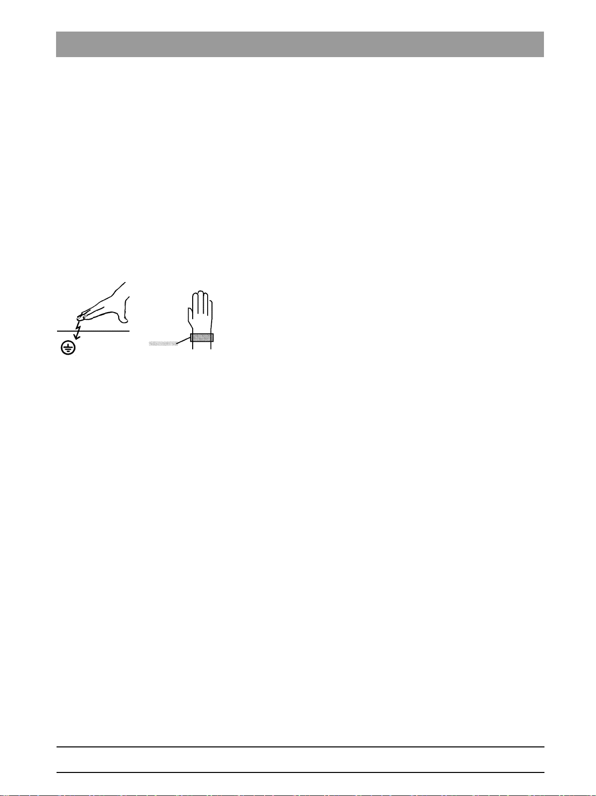
Electrostatic discharge
Electrostatic discharge (abbreviated: ESD – ElectroStatic Discharge)
Electrostatic discharge from people can damage electronic components
when the components are touched.
Touch a ground point to discharge static electricity before touching any
boards.
bеЦдблЬ
63 03 452 D3352
D3352.031.05.08.02 10.2015
13
3Unit description Sirona Dental Systems GmbH
A
B
C
3.1System versions Installation Manual ORTHOPHOS XG 3D / Ceph
Unit description
3
3.1
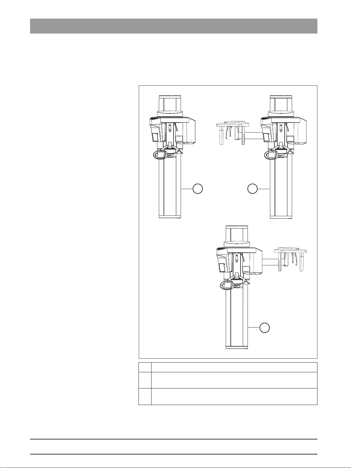
System versions
XG3D device version
A ORTHOPHOS XG 3D, digital volume tomograph
B ORTHOPHOS XG 3D/Ceph,
digital volume tomograph with cephalometer, left-arm version
C ORTHOPHOS XG 3D/Ceph,
digital volume tomograph with cephalometer, right-arm version
14 D3352.031.05.08.02 10.2015
63 03 452 D3352
Sirona Dental Systems GmbH 3Unit description
ORTHOPHOS
402,5
15 7/8”
2249
88 1/2”
1950
76 3/4”
A
Installation Manual ORTHOPHOS XG 3D / Ceph 3.2Dimensions/Space requirements
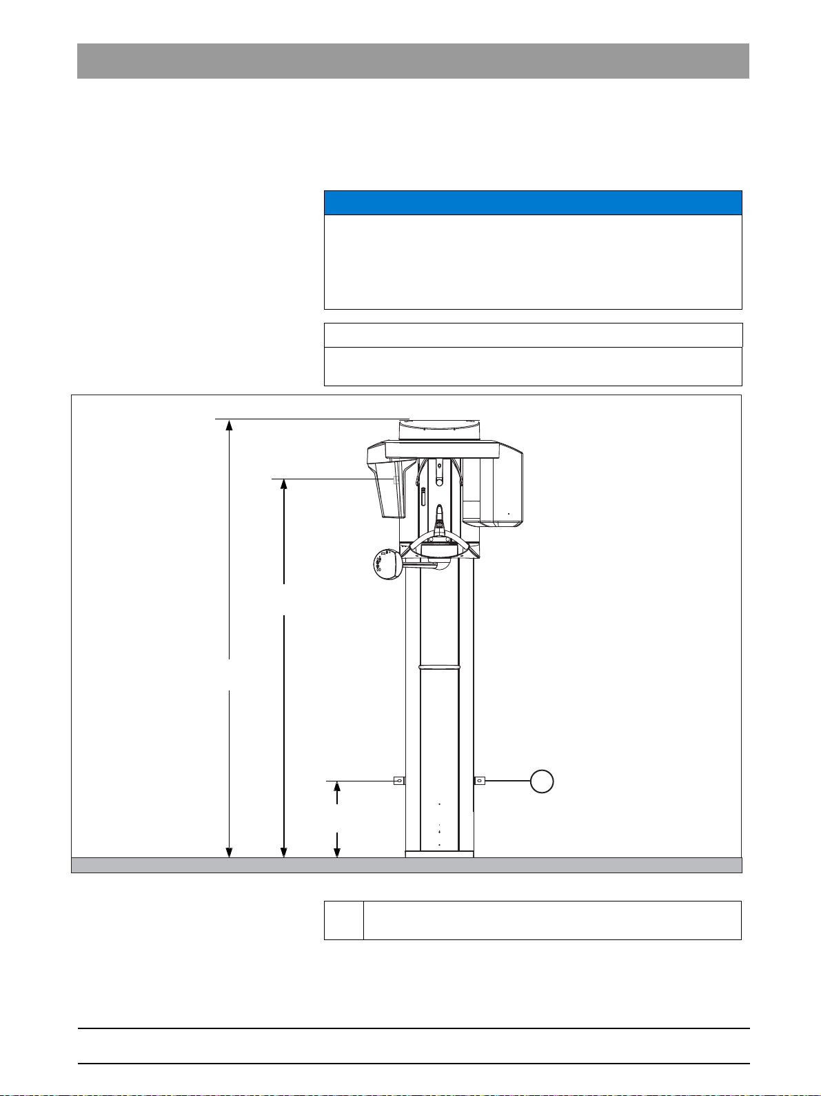
3.2
Dimensions/Space requirements
3.2.1 Front view
NOTICE
Unit can travel to the ceiling.
The minimum ceiling height should be 2.10 m (82 3/4"). If the ceiling
height is lower than 2.27 m (89 1/2") (max. travel height of 2.25 m (88 1/
2")), the travel height of the unit must be adjusted or limited prior to
startup via service routine S018.2.
IMPORTANT
The measurements on the drawings are specified in both mm and
inches.
Front view: XG 3D
bеЦдблЬ
63 03 452 D3352
D3352.031.05.08.02 10.2015
A Alternative fastening if it is not possible to screw the unit onto the
floor. Order bracket separately.
These dimensions apply to installation of the unit without the floor stand.
Installation with the floor stand results in an additional 30 mm (1 1/4")
increase of all height dimensions (see also separate Installation
Requirements document).
15
3Unit description Sirona Dental Systems GmbH
1371
54”
1040
41”
410
16 1/2”
520
20 1/2“
min.
min.
1280
50 3/8”
1411
55 1/2
"
600
23 5/8”
min.
154
6”
395
15 1/2“
475
18 3/4“
3.2Dimensions/Space requirements Installation Manual ORTHOPHOS XG 3D / Ceph
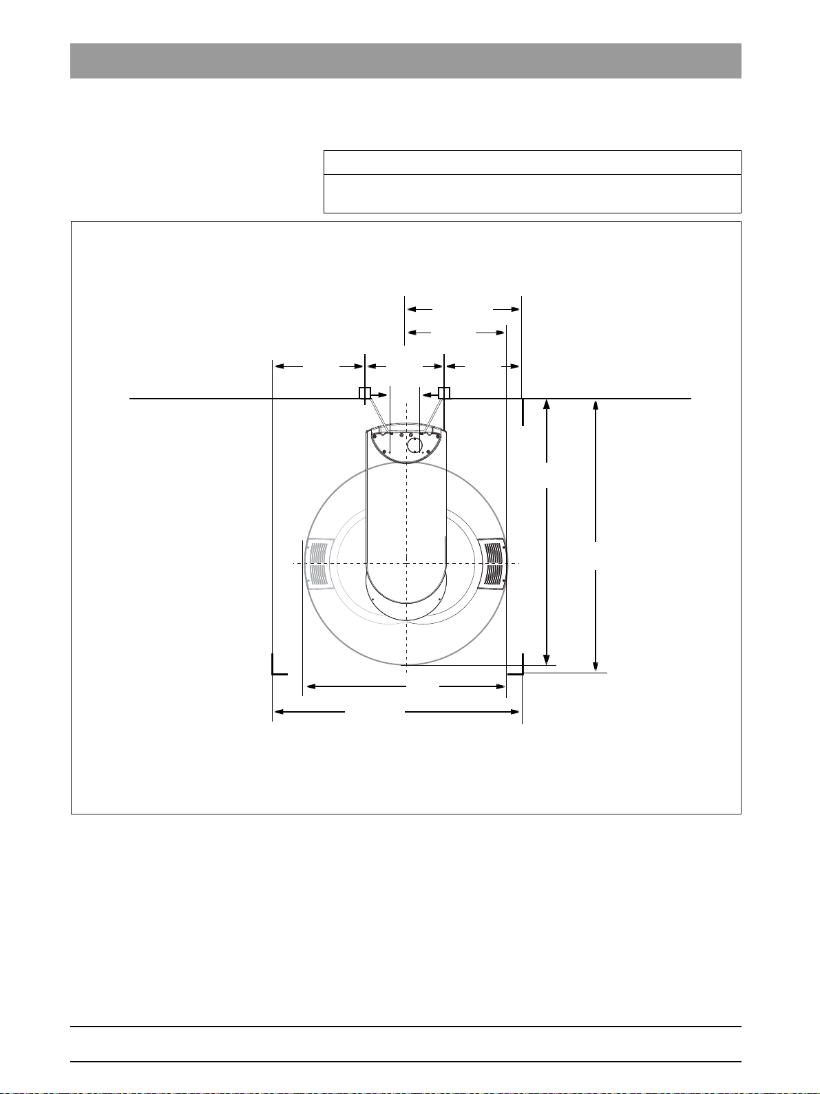
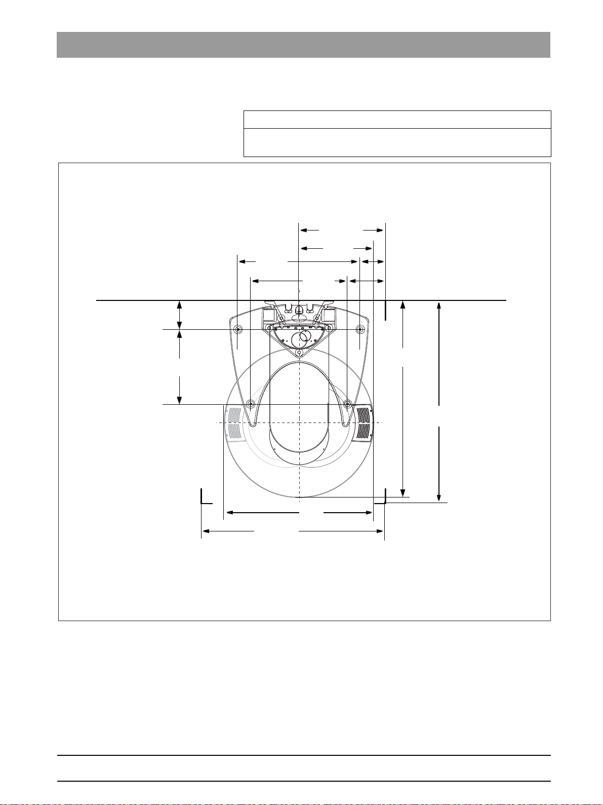
3.2.2 Top view
IMPORTANT
The measurements on the drawings are specified in both mm and
inches.
Top view: XG 3D
16 D3352.031.05.08.02 10.2015
63 03 452 D3352
Sirona Dental Systems GmbH 3Unit description
1371
54”
1040
41”
520
20 1/2“
min.
min.
1280
50 3/8”
1411
55 1/2
"
min.
850
33 1/2“
520
20 1/2“
200
7 7/8“
675
26 1/2“
600
23 5/8”
263
10 3/8“
175
67/8“
Installation Manual ORTHOPHOS XG 3D / Ceph 3.2Dimensions/Space requirements
3.2.3 Top view of floor stand
IMPORTANT
The measurements on the drawings are specified in both mm and
inches.
Top view of floor stand: XG 3 / 5 / 3D / 3D ready
bеЦдблЬ
63 03 452 D3352
D3352.031.05.08.02 10.2015
17
3Unit description Sirona Dental Systems GmbH
C
B
A
3.3Mounting options Installation Manual ORTHOPHOS XG 3D / Ceph
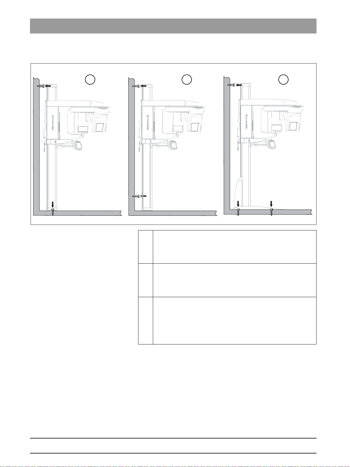
3.3
Mounting options
Mounting options: XG 3D
A Standard version
Wall-mounted installation with 1 wall holder
fastening if both wall and floor installation are possible on-site
(see section "Standard version [ → 36]").
B Option 1
Wall-mounted installation with 2 wall holders
fastening) if only wall installation is possible on-site (see section
".Option 1: with second wall holder [ → 38]".
C Option 2
Installation using a floor stand and 1 wall holder
possible to mount the unit on the wall and on the floor on-site and
x-rays are often taken while the patient is seated on a chair →
better positioning of seated patient (see section "Option 2: Floor
stand installation [ → 39]".
(short) and floor
(short) (and no floor
(long) if it is
18 D3352.031.05.08.02 10.2015
63 03 452 D3352
Sirona Dental Systems GmbH 3Unit description
C
B
A
Installation Manual ORTHOPHOS XG 3D / Ceph 3.4Installation versions
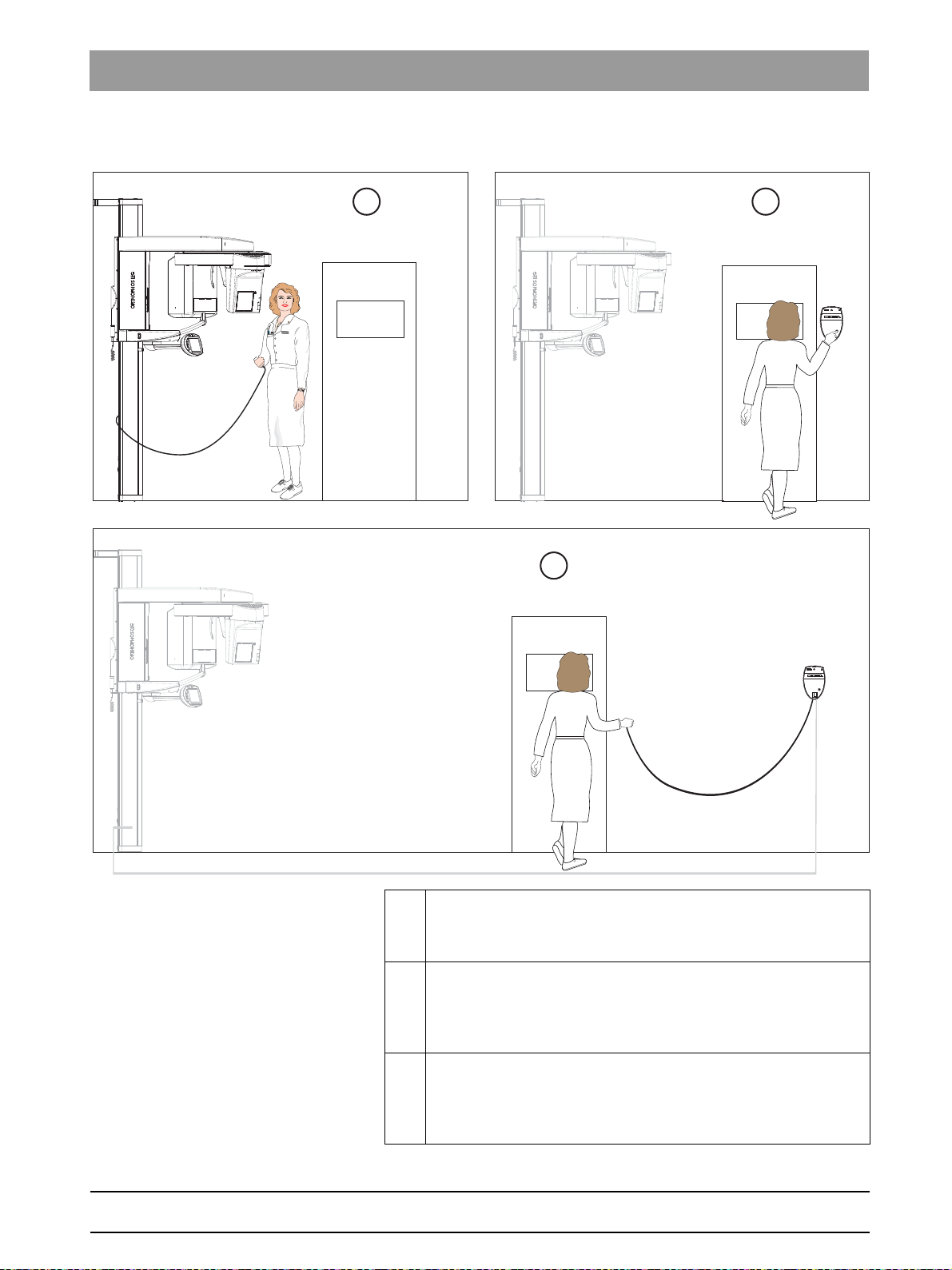
3.4
Installation versions
Installation versions: XG 3D
bеЦдблЬ
63 03 452 D3352
D3352.031.05.08.02 10.2015
A Standard installation
Unit
without remote control with release button on the coiled cable
in the treatment room.
B Installation version 1
C Installation version 2
Unit
with remote control
button on the coiled cable.
Without coiled cable [ → 68]).
Unit
with remote control
button on the coiled cable.
spiral cable [ → 69]).
outside the X-ray room
(see section Installation version 1:
outside the X-ray room
(see section Installation version 2: With
without release
with release
19

4Delivery and transport Sirona Dental Systems GmbH
A
B
A
4.1Delivery Installation Manual ORTHOPHOS XG 3D / Ceph
Delivery and transport
4
4.1
Delivery
Damage following delivery
NOTICE
Possible transport damage
If the shipment was damaged during transport, document all damage
carefully and contact the responsible carrying agent immediately.
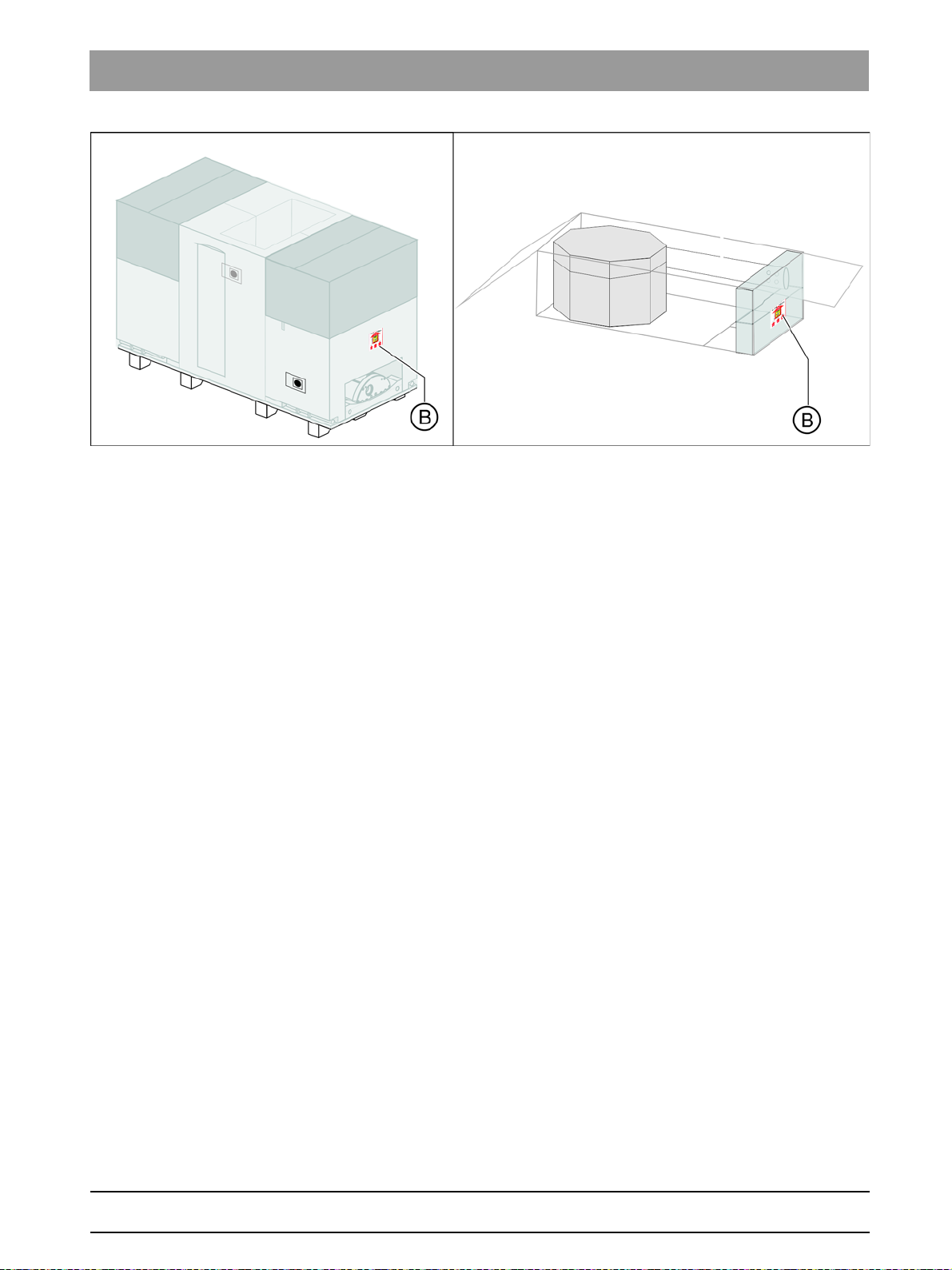
Indicators
Shock indicators: XG 3 / 5 / 3D / 3Dre ady / SL
Two shock indicators (A) are attached to the side of the unit packaging to
indicate whether the unit was exposed to a shock during transport.
● White indicator: No shock
● Red indicator: Shock
20 D3352.031.05.08.02 10.2015
63 03 452 D3352
Sirona Dental Systems GmbH 4Delivery and transport
Installation Manual ORTHOPHOS XG 3D / Ceph 4.1Delivery
Tilt indicators: XG 5 / 3D / 3Dready / SL
Tilt indicators (B) are attached to the panoramic unit and X-ray detector
packaging to indicate whether the units were improperly transported.
● Red indicator: Improper transport
The display of improper transport doesn't necessarily mean that the unit
is damaged.
bеЦдблЬ
Make a note on the delivery slip that the indicator is activated. Ensure that
the driver from the transport company confirms this on the delivery slip.
Fax the delivery slip to the Sirona Customer Service Center (CSC).
Enter the state of the indicators in the startup report in the case of
warranty claims.
Disposal of packaging materials
Disposal of packaging materials
Return the packaging materials to Sirona or dispose of them in
compliance with the legal regulations applicable in your country.
63 03 452 D3352
D3352.031.05.08.02 10.2015
21
4Delivery and transport Sirona Dental Systems GmbH
4.1Delivery Installation Manual ORTHOPHOS XG 3D / Ceph
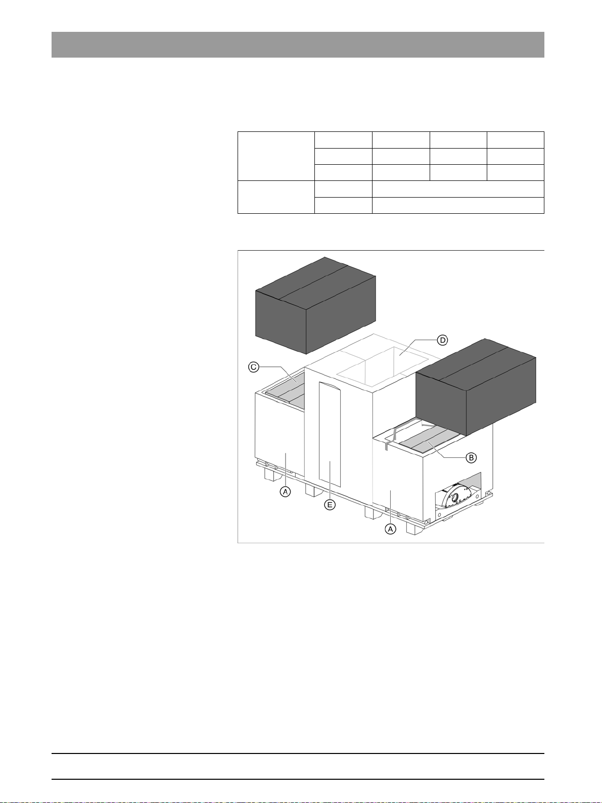
4.1.1 ORTHOPHOS XG 3D
Dimensions and weight
Dimensions Length Width Height
in cm 199 69 122
in inches 78 3/4 27 1/8 48
Weight in kg 183
in lbs 404
Scope of supply
The packaging of the X-ray unit is designed both for protection during
transport and as an installation aid. Therefore, please remove only the
surrounding packaging prior to installation. Please leave the Styrofoam
packaging and transport pallet attached to the unit. Save the two lateral
Styrofoam packaging parts for later use as an installation aid (A).
63 03 452 D3352
22 D3352.031.05.08.02 10.2015
Sirona Dental Systems GmbH 4Delivery and transport
Installation Manual ORTHOPHOS XG 3D / Ceph 4.1Delivery
A Installation aid (please save the two lateral Styrofoam packaging
parts)
Scope of supply:
B ● Software 2D / 3D
● Accessories and hygienic protective sleeves [ → 27]
● Installation material 1+2 [ → 36]
● Safety strap
● Needle phantom OP XG, adjustment phantom ceph OP XG
3D,
constancy test phantom OP XG 3D, contrast element OP XG
● Geometry phantom
● Pan sensor, ceph sensor (optional)
C ● Complete 3D module
● 3D cover attachment set: top 3D module, bottom 3D module
D Remote control (optional)
E Profile cover
bеЦдблЬ
63 03 452 D3352
D3352.031.05.08.02 10.2015
23
4Delivery and transport Sirona Dental Systems GmbH
A
B
2
1
C
D
E
F
F1
F2
F3
F4
F5
4.1Delivery Installation Manual ORTHOPHOS XG 3D / Ceph
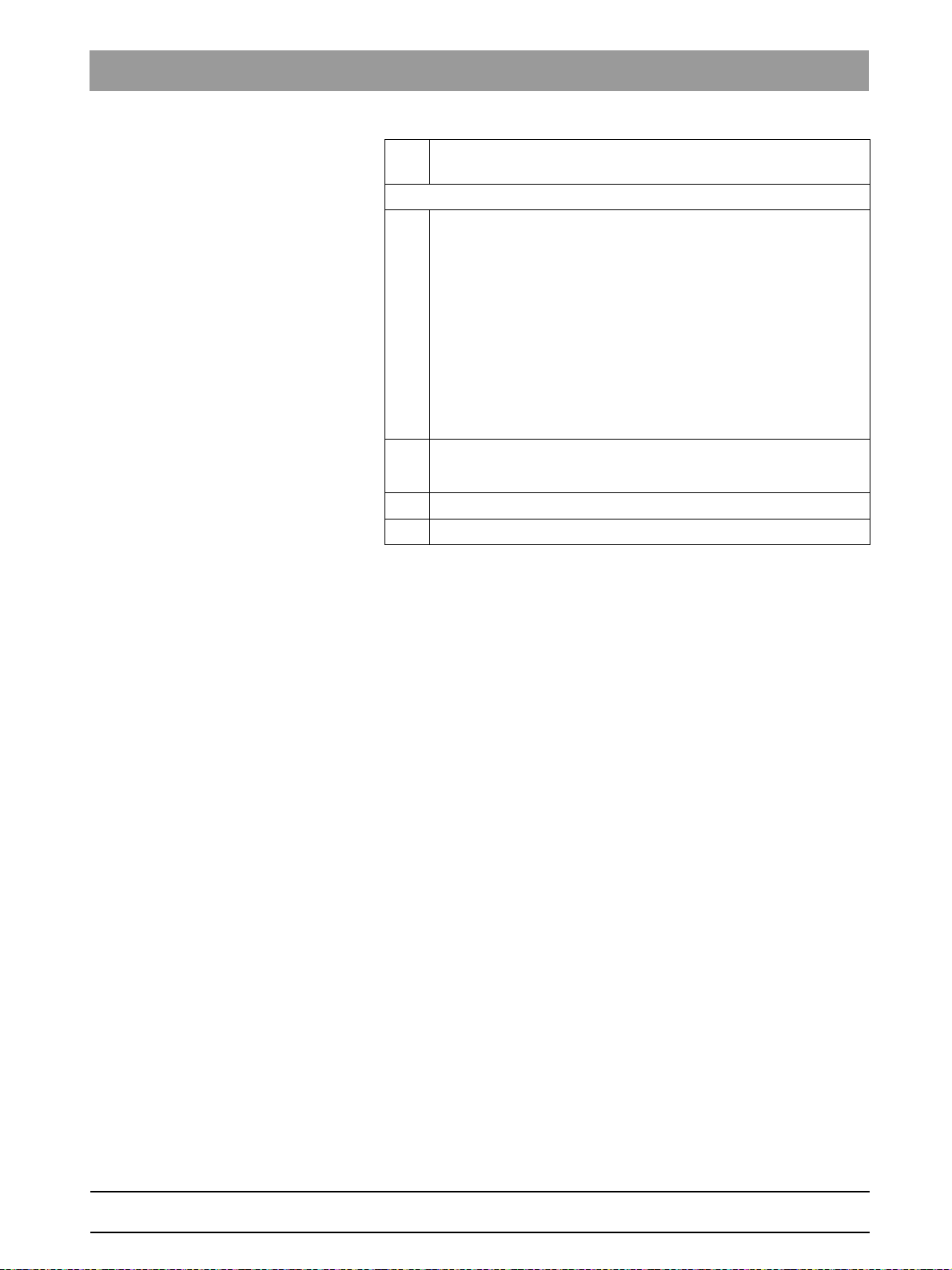
4.1.1.1
Accessories
A Forehead support and
Temple support
B Buttons for forehead and temple support (3x)
C TMJ supports 1 and
TMJ support 2
D Ear holders (4x)
E Buttons for TMJ supports (2x)
(1x)
(2x)
(1x)
(1x)
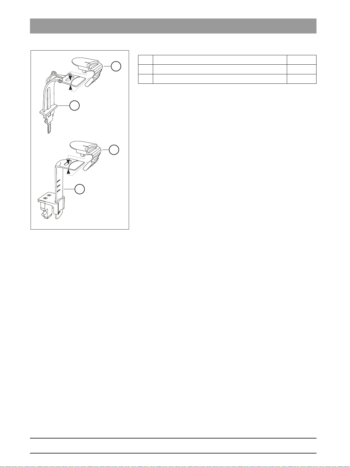
F Chin rest accessories 1x
F1 Bite block (5x)
F2 Bite block rod (1x)
F3 Bar (1x)
F4 Chin pad (1x)
F5 Chin rest (1x)
24 D3352.031.05.08.02 10.2015
63 03 452 D3352
Sirona Dental Systems GmbH 4Delivery and transport
J
I
H
G
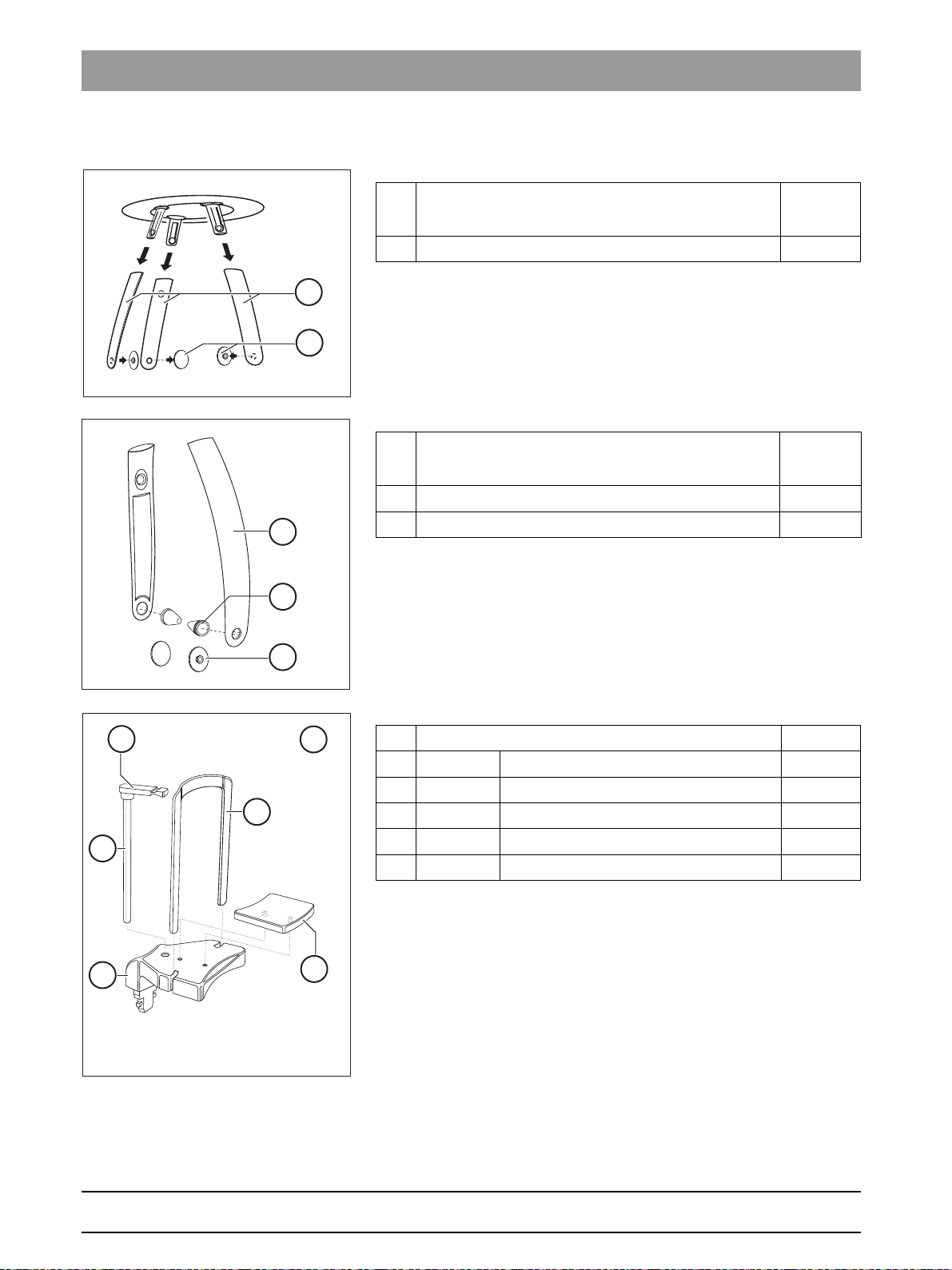
Installation Manual ORTHOPHOS XG 3D / Ceph 4.1Delivery
G Contact segment blue (1x)
H Bite block part blue (1x)
I Contact segment standard yellow (1x)
J Bite block part standard yellow (1x)
bеЦдблЬ
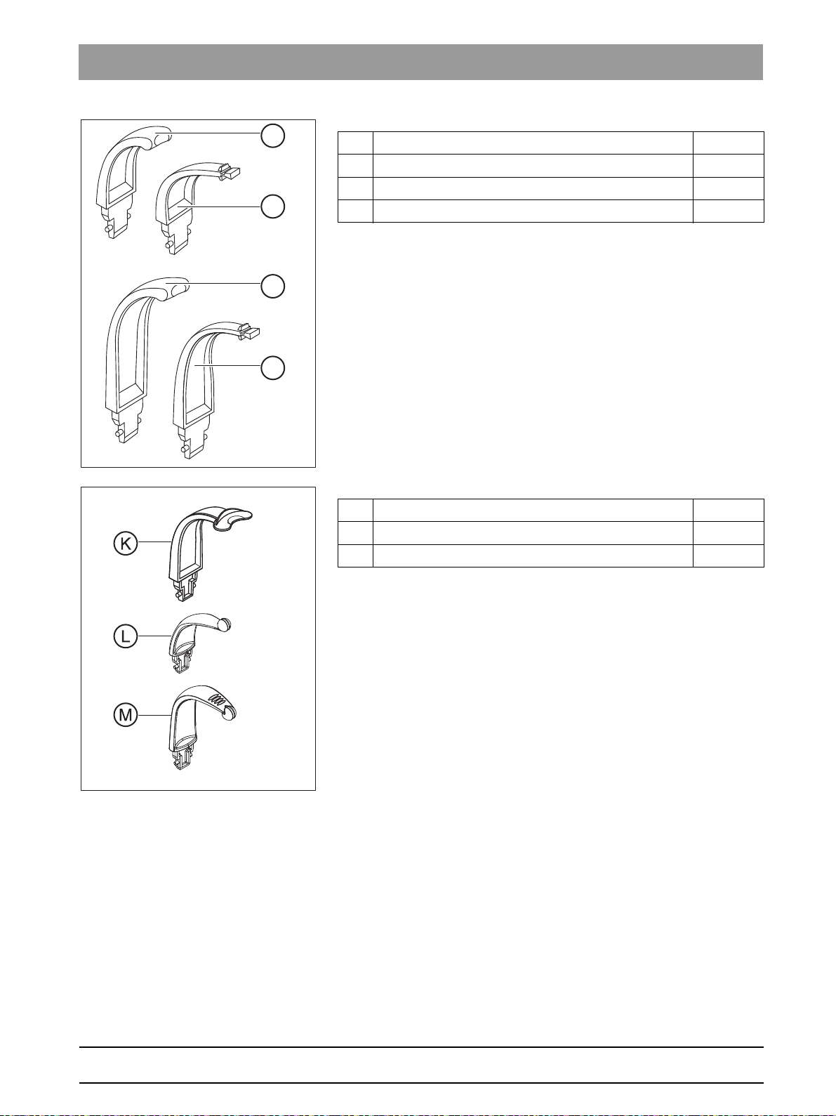
K Rigid bite block (1x)
L Bite block plate holder OK (upper jaw) (1x)
M Bite block plate holder UK (lower jaw) (1x)
63 03 452 D3352
D3352.031.05.08.02 10.2015
25
4Delivery and transport Sirona Dental Systems GmbH
O
P
Q
Q
4.1Delivery Installation Manual ORTHOPHOS XG 3D / Ceph
O Occlusal bite block (1x)
P Universal bite block (1x)
Q Bite block foam (100x)
26 D3352.031.05.08.02 10.2015
63 03 452 D3352
Sirona Dental Systems GmbH 4Delivery and transport
E
D
C
B
A
F
Installation Manual ORTHOPHOS XG 3D / Ceph 4.1Delivery
4.1.1.2
Hygienic protection
bеЦдблЬ
63 03 452 D3352
D3352.031.05.08.02 10.2015
A Forehead and temple supports (500x)
B Bite block (500x)
C Chin rest and bar (100x)
D Bite block parts and
E Rigid bite block 500x
F XG hygienic handle (100x)
(500x)
contact segments
27

4Delivery and transport Sirona Dental Systems GmbH
A
B
C
4.1Delivery Installation Manual ORTHOPHOS XG 3D / Ceph
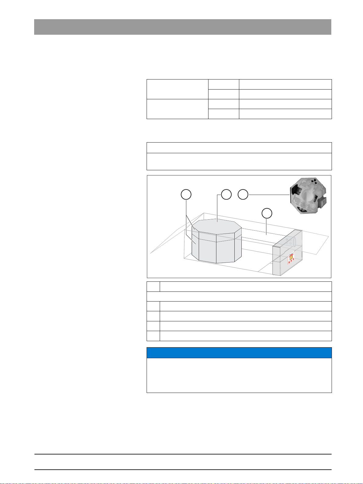
4.1.1.3
3D module
3D module delivery
Dimensions and weight
Dimensions Length Width Height
in cm403623
in inches 15 3/4 14 1/8 9
Weight in kg 6
in lbs 13 1/4
Scope of supply
A 3D module
B NOTICE! The cover plate is only attached loosely.
63 03 452 D3352
28 D3352.031.05.08.02 10.2015
Sirona Dental Systems GmbH 4Delivery and transport
B
C
D
+
A
Installation Manual ORTHOPHOS XG 3D / Ceph 4.1Delivery
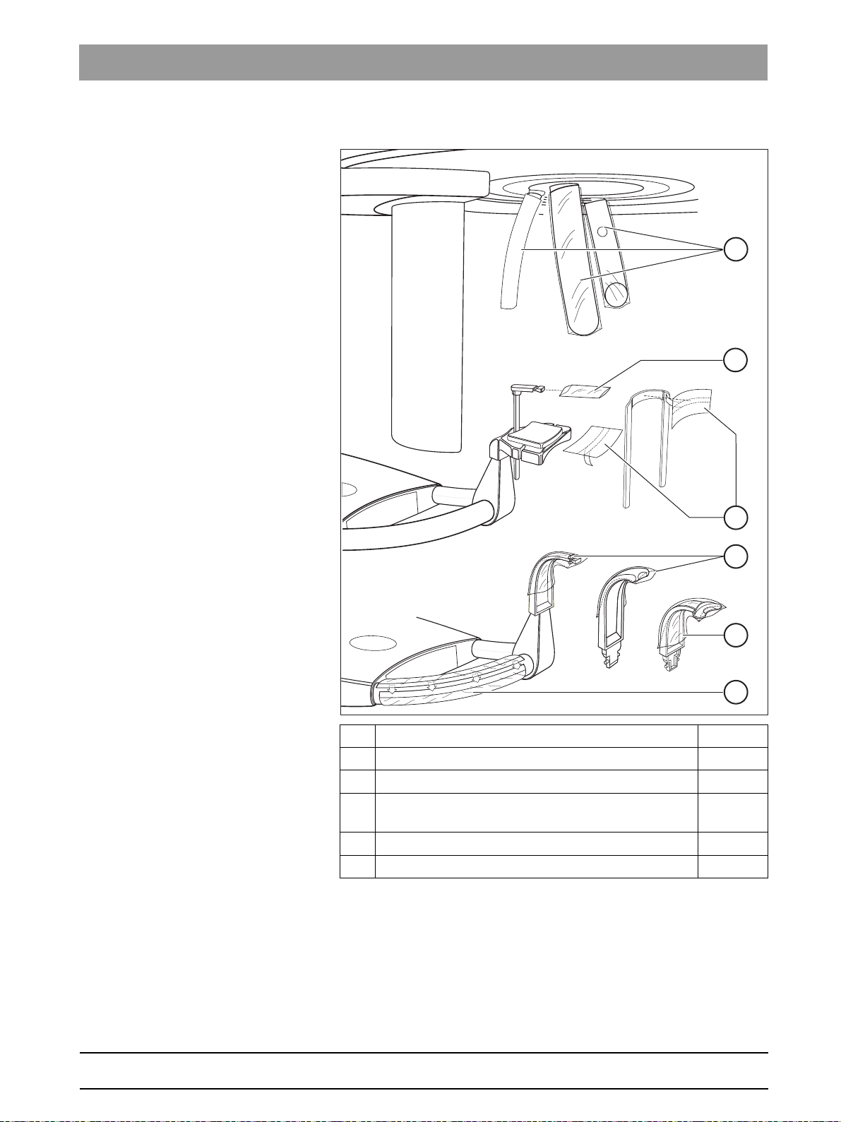
4.1.2 Ceph arm
Dimensions and weight
Dimensions (cm) 175 x 78 x 73
(inches) 68 7/8 x 30 3/4 x 28 3/4
Weight (kg) 40
(lbs) 88
Scope of supply
IMPORTANT
The right-handed ceph arm (only available for ORTHOPHOS XG 3D/
Ceph) is packed laterally reversed.
A Styrofoam packaging
Scope of supply:
B Ceph arm
C Accessories [ → 30] and hygienic protective sleeves [ → 30]
D Installation material [ → 81]
E Ceph sensor
Damage to the cephalomet er
NOTICE
Risk of damage to the cephalometer
The cephalometer inside the styrofoam part (A) is a sensitive unit and is
at risk of damage when mounting the ceph arm. Remove the styrofoam
packaging material only following installation.
bеЦдблЬ
63 03 452 D3352
D3352.031.05.08.02 10.2015
29
4Delivery and transport Sirona Dental Systems GmbH
20
30
40
50
C
A
B
20
30
40
50
B
A
4.1Delivery Installation Manual ORTHOPHOS XG 3D / Ceph
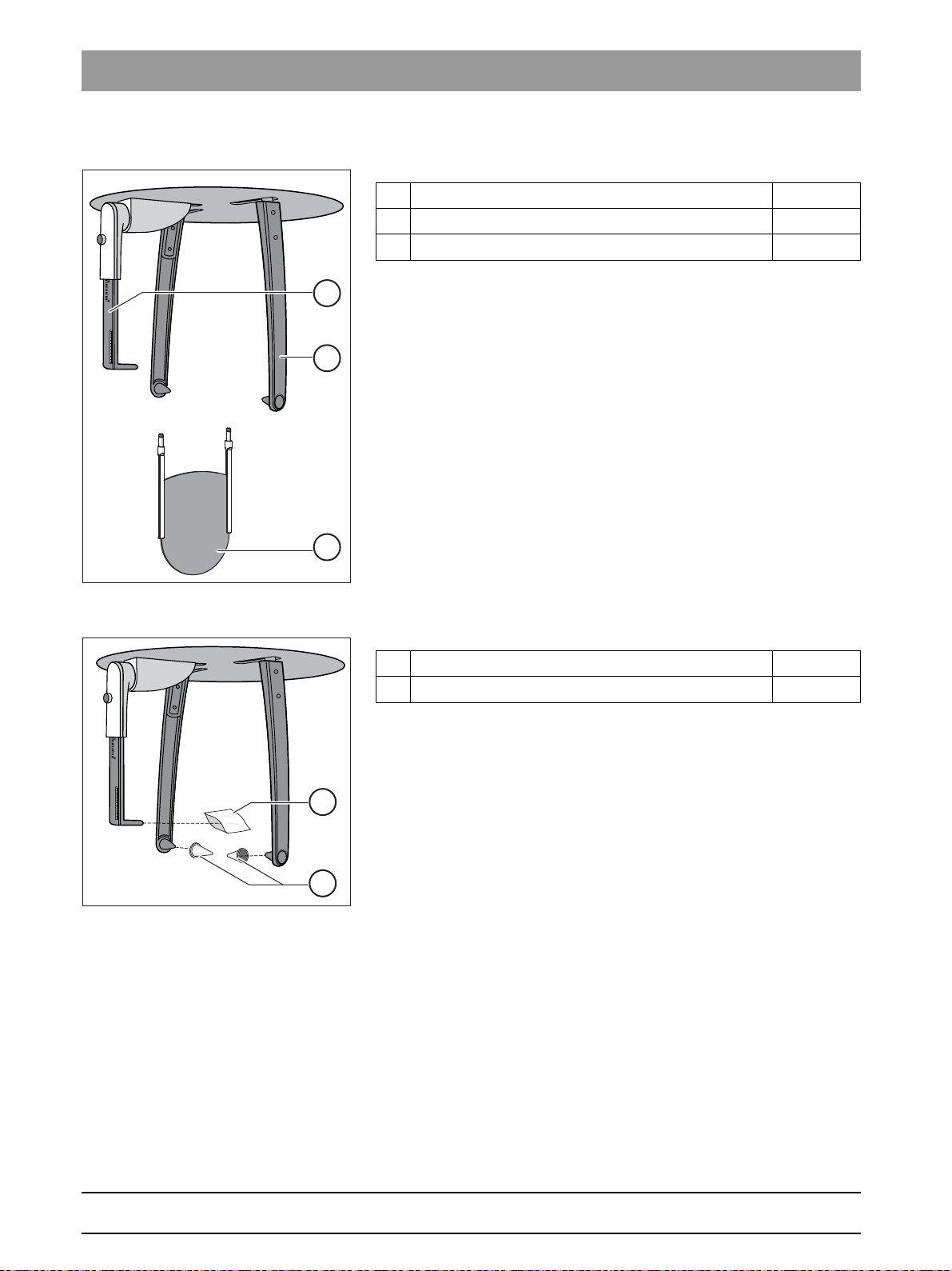
4.1.2.1
Accessories
A Nose support (1x)
B Ear plug holders with ear plug fixation (2x)
C Carpus support plate (1x)
4.1.2.2
Hygienic protection
A Hygienic protective sleeves for nose support (100x)
B Hygienic caps for ear plugs, sterilizable (4x)
30 D3352.031.05.08.02 10.2015
63 03 452 D3352
Loading...