


|
|
8YVFMRIW 8 8 '328630 6EGIV QMRM |
|
6ITEMV -RWXVYGXMSRW |
|

1
2
3
4
5
6
7
8
9
10
11
12
13
14
15
16
17
18
19
20
21
22
23
24
List of Contents |
|
Special tools ................................................................................. |
3 |
Replacing the Rotor Assembly ..................................................... |
4 |
Replacing the Spray Cap .............................................................. |
6 |
Dismantling the coupling fitting ..................................................... |
8 |
Replacing the bill valve ............................................................... |
10 |
Replacing the Halogen Lamp - W&H / Bien Air .......................... |
11 |
Dismantling the head drive ......................................................... |
12 |
Assembling the head housing .................................................... |
13 |
Assembling the coupling fitting ................................................... |
14 |
Functional inspection .................................................................. |
15 |
Technical Data - Turbines with Sirona Connection .................... |
16 |
Technical Data - Turbines with KaVo Connection ...................... |
17 |
Technical Data - Turbines with W&H Connection ...................... |
18 |
Technical Data - Turbines with Bien Air Connection .................. |
19 |
Technical Data - Turbines with NSK Connection ....................... |
20 |
Technical Data - Turbines with NSK QD Connection ................. |
21 |
Spare parts - T2 CONTROL / Racer / mini ................................. |
22 |
Spare parts - T3 Racer / mini ..................................................... |
23 |
Spare parts - Turbine with Sirona Connection ............................ |
24 |
Spare parts - Turbine with KaVo Connection ............................. |
25 |
Spare parts - Turbine with W&H Connection .............................. |
26 |
Spare parts - Turbine with Bien Air Connection ......................... |
27 |
Spare parts - Turbine with NSK Mach Connection ..................... |
28 |
Spare parts - Turbine with NSK QD-J Connection ..................... |
29 |
Turbines T2 / T3 (CONTROL / Racer / mini) |
D 3355.076.01.02.02 |
01.2003 |
2 |
|
|
|
|

Special tools |
1 |
|
|
B (59 34 554)
A (58 28 855)
C (33 27 793)
Turbines T2 / T3 (CONTROL / Racer / mini) |
D 3355.076.01.02.02 |
01.2003 |
3 |
|
|
|
|
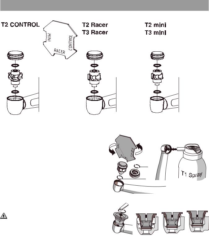
Replacing the Rotor Assembly 2
Sirona |
Sirona |
KaVo |
KaVo |
W&H |
W&H |
Bien Air |
Bien Air |
NSK Mach |
NSK Mach |
|
NSK QD (T3 Racer) |
Sirona |
KaVo |
W&H |
Bien Air |
NSK |
NSK QD (T3 mini) |
1. Grasp the pressure cover with the matching recess of |
A (58 28 855) |
|
|
key A; unscrew and remove cover. |
|
|
|
Remove the defective rotor assembly. |
|
|
|
Remove O-rings 72/72a from cover and housing |
|
|
|
(tweezers, probe). |
|
|
|
The housing of the turbine head must be clean, |
|
|
|
remove dirt and bearing residue if necessary. |
72 |
|
|
Please clean using only T1 Spray. |
|
|
|
|
|
|
|
With each rotor change, basically both O-rings |
72a |
|
|
must be exchanged! |
|
|
|
The two new O-rings must not be inserted twisted. |
|
|
|
To insert the new O-ring in the turbine head housing |
|
|
|
you must first attach the guide bush supplied FB in |
|
|
|
the turbine head housing. |
72a |
|
|
The hole in the guide bush enables placing the |
FB |
Racer |
mini |
O-ring 72a exactly into the groove. |
CONTROL |
||
|
|
|
|
ATTENTION! |
|
|
|
Do not use a pointed object to insert! |
|
|
|
Turbines T2 / T3 (CONTROL / Racer / mini) |
D 3355.076.01.02.02 |
01.2003 |
4 |
|
|
|
|

Replacing the Rotor Assembly
A (58 28 855)
2. Carefully insert the new rotor assembly in the cover.
Screw cover with rotor assembly into turbine head by hand and screw it tight with the prescribed tool A.
ATTENTION!
Otherwise there is a danger of the cover coming undone, thus allowing the rotor and the drilling instrument to fall into the patient’s throat.
Then spray for one second.
3. Clamp FG instrument and stabilize it in the O-ring seats by rotating and pulling the rotor assembly.
Let turbine run briefly without cooling spray.
Turbines T2 / T3 (CONTROL / Racer / mini) |
D 3355.076.01.02.02 |
01.2003 |
5 |
|
|
|
|

Replacing the Spray Cap 3
Spray repair set*: |
|
|
1 |
nozzle spray |
58 66 723 |
2 |
nozzle spray |
58 66 731 |
3 |
nozzle spray |
58 66 749 |
* contains: Tools K / L / N 2 Spray rings 4 O-rings
4 screws
Spray insert**:
L
1 |
nozzle spray |
58 66 699 |
2 |
nozzle spray |
58 66 707 |
3 |
nozzle spray |
58 66 715 |
** contains: Tools K / L / N 1 Spray ring 2 O-rings
2 screws
N K
i
Notice:
Similar to T1 LINE / T1 CLASSIC and Turbine T1
Turbines T2 / T3 (CONTROL / Racer / mini) |
D 3355.076.01.02.02 |
01.2003 |
6 |
|
|
|
|
Use the spray key K to unscrew the spray screw 252 counter-clockwise and remove it.
For turbines with FG chucks, use the end of the key with the thin guide shaft K.2.
The end of the key with the thick guide shaft K.1 is used for motor-driven handpieces with a WB chuck.
Then insert the extracting tool L in the spray cap 247. Pinch the extracting tool and pull the spray cap 247 out of the head.
ATTENTION!
Do not use O-ring and spray screw any more.
Clean the chamber* in the head thoroughly. If necessary clean the air and water channels thoroughly but carefully with cleaning wires M.
Then let the turbine run briefly with spray to rinse the (air and water) channels.
Before inserting the new spray cap 247, you must slip an O-ring 251 onto it with the attachment sleeve N. This is done by inserting the spray cap in the attachment sleeve up to the stop and then sliding a new O-ring over the sleeve and onto the cap.
ATTENTION!
The O-ring 251 has not to damaged and must not come to lie in the ring groove**.
Then spray the O-ring with T1 Spray, set the position of the spray nozzle(s) and insert the spray cap in the head.
Use the spray key to fasten the spray cap with a new spray screw.
Then run the turbine with cooling spray and check the exit spray.
Replacing the Spray Cap
252
K.2
K
K.1
*
247
L
M
247
 **
**
N
251
Turbines T2 / T3 (CONTROL / Racer / mini) |
D 3355.076.01.02.02 |
01.2003 |
7 |
|
|
|
|

Dismantling the coupling fitting |
4 |
|
|
Overview of Turbines
Sirona Connection
KaVo Connection
W&H Connection
Bien Air Connection
NSK Mach Connection
NSK QD-J Connection
T2 CONTROL
T2 Racer
T2 mini
T3 Racer
T3 mini
T2 CONTROL
T2 Racer
T2 mini
T2 CONTROL
T2 Racer
T2 mini
T3 Racer
T3 mini
T2 CONTROL
T2 Racer
T2 mini
T3 Racer
T3 mini
T2 CONTROL
T2 Racer
T2 mini
T3 Racer
T3 mini
T3 Racer
T3 mini
Turbines T2 / T3 (CONTROL / Racer / mini) |
D 3355.076.01.02.02 |
01.2003 |
8 |
|
|
|
|

Dismantling the coupling fitting
Dismantling the coupling fitting according to Sirona
Connection:
1. |
Unscrew the outer sleeve 111. |
|
2. |
Remove the coupling fitting 302 from the |
111 |
|
frontpart of the turbine. |
|
302
ATTENTION!
Note the two balls 83 which belong to the lock-in mechanism and can fall out
with the broken spring washer 81.
83
81
3. Loosen the centering disk 93 carefully with a screwdriver from the coupling fitting 302 and take it out. Take out the spring washer 81 an take off the balls 83.
93
Turbines T2 / T3 (CONTROL / Racer / mini) |
D 3355.076.01.02.02 |
01.2003 |
9 |
|
|
|
|
 Loading...