


 Loading...
CDR PanElite |
j~бенЙе~еЕЙ=fелнкмЕнбзел==== |
English |

General information
ATTENTION !
Proper shielding of room and operator position is essential.
Since these requirements vary from state to state it is the assembler's/installer's responsibility that all local radiation safety requirements are met.
2
Schick Technologies, Inc.
Maintenance Instructions CDR PanElite
61 88 085 D3352 D3352.103.02.01.02

Schick Technologies, Inc.
Maintenance Instructions CDRPanElite
Contents
1 |
General ................................................................................................................................ |
|
5 |
2 |
Visual Check ....................................................................................................................... |
|
6 |
3 |
Indicator Lights and audible Signal.................................................................................. |
7 |
|
4 |
Power supply adequacy..................................................................................................... |
|
9 |
5 |
kV – verification, kV ramp during panoramic exposure ............................................... |
10 |
|
6 |
Tube Current Verification ................................................................................................ |
|
14 |
7 |
Exposure Time Verification ............................................................................................. |
|
17 |
8 |
Checking the X-Ray Beam............................................................................................... |
|
20 |
|
8.1 |
Diaphragm/system adjustment menu ..................................................... |
20 |
9 |
Checking the X-Ray Beam for panorama exposure ...................................................... |
22 |
|
|
9.1 |
Preparing the Pan adjustment ................................................................ |
22 |
|
9.2 |
Checking the Pan sensor adjustment ..................................................... |
23 |
|
9.3 |
Checking the Pan diaphragm adjustment............................................... |
25 |
|
9.4 |
Checking the Pan filter adjustment ......................................................... |
27 |
|
9.5 |
Checking the Pan symmetry................................................................... |
29 |
10 |
Checking the X-Ray Beam for cephalometer exposure................................................ |
31 |
|
|
10.1 |
Preparing the Ceph adjustment .............................................................. |
31 |
|
10.2 |
Checking the Ceph primary diaphragm adjustment................................ |
32 |
|
10.3 |
Checking the Ceph rotation fixpoint adjustment ..................................... |
35 |
|
10.4 |
Checking the Ceph main X-ray beam direction adjustment.................... |
37 |
11 |
Checking the alignment of the ear plugs ....................................................................... |
39 |
|
|
11.1 |
Preparing the ear plugs .......................................................................... |
39 |
|
11.2 |
Checking the ear plug alignment ............................................................ |
40 |
12 |
Checking the laser............................................................................................................ |
|
43 |
English
61 88 085 D3352 |
3 |
D3352.103.02.01.02 |
Schick Technologies, Inc.
Maintenance Instructions CDRPanElite
4 |
61 88 085 D3352 |
D3352.103.02.01.02 |

Schick Technologies, Inc. |
1 General |
Maintenance Instructions CDR PanElite |
|
1 General
To stay in compliance with the DHHS requirements the CDR PanElite must be maintained annually.
It is the responsibility of the user to insure that the equipment is maintained with the manufacturer's recommended Maintenance Instructions to insure compliance with the Federal Performance Standard.
The manufacturer and the assembler/installer are relieved from responsibility in those cases where the user fails to have the manufacturer's recommended maintenance performed.
The actual maintenance inspection and consequent service must be accomplished by a trained serviceman. Neither the inspection nor service is part of the equipment warranty.
Technical instructions required
Operating Instructions
Service Manual
Instruments and adjustment tools required
All measuring devices must be suitable for measurements on the mains potential.
This includes the pulse counter.
This means: A voltage of 1000 V between a connection and ground must be possible.
1.Digital multimeter Fluke 87 III or equivalent.
Accuracy:
DC voltage ± 0.1 % of reading plus 0.02% of range DC current ± 0.4 % of reading plus 0.1% of range.
2.Electromechanical pulse counter, model KESSLER ELLIS KT 203 ±1 pulse, or equivalent..
3.Adjustment set with alignment tool for X-ray beam , test block and needle phantom delivered with the unit, (customer's property).
 ATTENTION
RADIATION!
Observe the radiation protection guide lines as outlined in the Operating Instructions manual.
X-radiation is emitted as long as the exposure switch is depressed.
The X-ray indicator must light up on the Control Pad during radiation. An acoustic signal should also be heard.
61 88 085 D3352 D3352.103.02.01.02
Power Supply Adequacy
To assure that the CDR PanElite system performance is in accordance with Schick specifications, an adequate power supply for permanent installation is essential.
The Federal Performance Standard for diagnostic X-ray units, code of Federal Regulations, Title 21 CFR, Subchapter J, mandates an adequate power supply.
Duty Cycle
Between exposures a minimum cool-off time is maintained (automatic exposure blockage, see Operating Instructions manual).
Operating Instructions
During measurements and adjustments it is necessary to energize or de-energize the unit. For all operating steps please refer to the Operating Instructions manual.
CAUTION with PC Boards!
All PC boards are fitted with electronic components sensitive to electrostatic discharge (ESD). Electrostatic charges are unavoidable due to friction caused by clothing, carpeting etc.
 ATTENTION
To prevent damage of electronic chips do not touch components.
Always handle circuit boards by their edges.
 ATTENTION
Electrical Shock Hazard!
Always turn unit OFF before connecting and disconnecting the test leads to the test points
ON
OFF
 WARNING
Life-threatening voltage on DX6.
5
English
2 Visual Check |
Schick Technologies, Inc. |
|
Maintenance Instructions CDR PanElite |
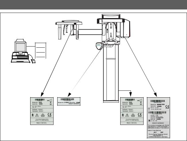
2 Visual Check
CDR |
Service |
Software |
•Look for mechanical damage that may affect radiation safety.
•Verify that all labels are affixed and legible.
Defaced labels must be replaced.
Order labels from Schick (address, see rear) in writing stating:
•Customer Name
•Customer Address
All Model Numbers with Serial Numbers should be legible on the unit for identification purposes. For serial numbers see also Installation Report.
6 |
61 88 085 D3352 |
D3352.103.02.01.02 |
Schick Technologies, Inc. |
3 Indicator Lights and audible Signal |
Maintenance Instructions CDR PanElite |
|
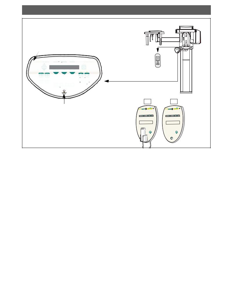
3 Indicator Lights and audible Signal
Unit ON LED
ON
OFF
P1 14.1 64 8
|
|
|
|
Remote |
|
|
|
|
This product complies with DHHS |
|
|
This product complies with DHHS |
|
||
|
regulations 21 CFR Subchapter J, |
|
|
regulations 21 CFR Subchapter J, |
|
||
|
applicable at date of manufacture. |
|
|
applicable at date of manufacture. |
|
||
|
Date of manufacture: |
|
|
|
Date of manufacture: |
|
|
|
Sirona Dental Systems GmbH |
|
|
Sirona Dental Systems GmbH |
|
||
|
Fabrikstraße 31 |
|
|
|
Fabrikstraße 31 |
|
|
|
D-64625 Bensheim, Germany |
|
|
D-64625 Bensheim, Germany |
|
||
Radiation indicator |
|
|
|
|
|
|
|
P 10 |
11.5 |
64 |
8 |
P 10 |
11.5 |
64 |
8 |
Program |
S |
kV |
m A |
Program |
S |
kV |
m A |
WARNING: THIS X-RAY UNIT MAY BE DANGEROUS TO PATIENT |
|
WARNING: THIS X-RAY UNIT MAY BE DANGEROUS TO PATIENT |
|||||
AND OPERATOR UNLESS SAFE EXPOSURE FACTORS AND OPERATING |
AND OPERATOR UNLESS SAFE EXPOSURE FACTORS AND OPERATING |
||||||
INSTRUCTIONS ARE OBSERVED. UNAUTHORIZED USE IS PROHIBITED. |
INSTRUCTIONS ARE OBSERVED. UNAUTHORIZED USE IS PROHIBITED. |
||||||
•Unit ON LED:
Press the main switch to the ”I” position to turn unit ON. Power ON tests to take about 1 minute.
The ”Unit ON LED” in the upper right corner of the user interface will then be lit".
•Testing the keys and the functions on the user interface.
–When the height is adjusted, an acoustic signal is active.
–If the forehead support functions correctly, the max. holding torque is still present.
–If remote is installed, test the remote keys and verify proper operation of the display.
–The exposure switch must not be defective or broken.
See also Operating Instructions under ”Preparing the Exposure” subchapter ”Switching the system on”.
English
61 88 085 D3352 |
7 |
D3352.103.02.01.02 |

3 Indicator Lights and audible Signal |
Schick Technologies, Inc. |
|
Maintenance Instructions CDR PanElite |
|
|
|
|
CAUTION RADIATION !
Observe Radiation Protection Guide Lines see Operating Instructions
menu keys
Unit ON LED
P1 |
14.1 64 8 |
submenu key |
Return key R
Radiation indicator
•Take an exposure:
–X-ray head must be in the initial position (If not, press return key R).
–Make sure that CDR PanElite Service program is ready to take an image.
For more details and possible error messages see Operating Instructions.
–Set the P1 exposure program using the menu keys.
–Select 68kV/8mA using submenu keys.
 CAUTION RADIATION
–Press and hold the exposure switch until the exposure terminates automatically.
–The exposure ends when the rotation and radiation switch off automatically.
–The radiation indication must light up during the exposure period.
–Simultaneously an audible beep must sound at the unit.
•Interrupt an exposure – deadman feature:
–Observe a cool-off time of max. 5 mins. between exposures (automatic exposure blockage).
–Setting same as above.
 CAUTION RADIATION
–Press the exposure switch until X-ray lights up and subsequently release – the exposure must terminate immediately. The radiation indicator lights up.
 ATTENTION
Defective light indicators constitute a safety hazard to the patient as well as to the operator.
The user is not permitted to use the unit, until repairs are made!
8 |
61 88 085 D3352 |
D3352.103.02.01.02 |
Schick Technologies, Inc. |
4 Power supply adequacy |
Maintenance Instructions CDR PanElite
4 Power supply adequacy
1. |
2. |
|
|
|
300 VAC |
3. |
|
|
|
K1 |
English |
n |
|
|
|
*o |
|
|
|
|
|
4. - 5. |
|
|
K1 |
|
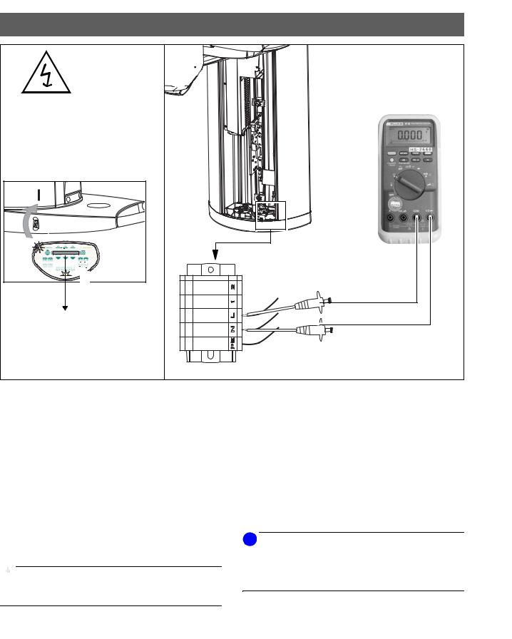
•To determine power supply adequacy, the line voltage drop during exposure must be measured.
1.Be sure power is disconnected at the central distribution panel!
•Remove front cover (for details see Service Manual).
2.Select 300VAC line voltage range on multimeter . Connect measuring leads to terminal K1, L and N.
3.Connect power and switch unit ON n.
Wait 1 min. for self-adjustment of the unit.
Press key R oto return X-ray tube head into the initial position.
4.Make sure that CDR PanElite Service program is ready to take an image.
5.Select highest exposure level e.g., 90kV/12mA.
 CAUTION RADIATION
– Press and hold the exposure switch until the meter reading is obtained.
Line voltage, no load: |
Max. permissible line volt- |
|
age drop: |
180 – 208V |
9V |
|
|
208 – 230V |
8V |
|
|
230 – 240V |
7.5V |
|
|
240 – 264V |
7V |
|
|
Record reading.
•Turn unit OFF.
•Remove meter leads and refit cover.
i NOTE
If the voltage drop is not within the specified range advise the customer, that an adequate power supply must be installed. Refer to Pre-Installation Instructions.
Disconnect unit and do not release for use!
61 88 085 D3352 |
9 |
D3352.103.02.01.02 |

5 kV – verification, kV ramp during panoramic exposure |
Schick Technologies, Inc. |
|
Maintenance Instructions CDR PanElite |
5kV – verification, kV ramp during panoramic exposure
1. |
 WARNING
The electronics of the X-ray tube assembly are always connected to line voltage.
Always switch the X-ray unit off and wait until V203 is no longer illuminated before contacting the test leads.
 WARNING
The test leads and measuring instruments used must have a dielectric strength of at least 1000V!
Be sure to use a battery-powered measuring instrument with shock-hazard-protected sockets.
Use only test leads with shock protection.
 ATTENTION
The X-ray tube assembly moves during the measurement. Therefore, be sure to use test leads of sufficient length and place the measuring instrument in a location where it is firmly seated so that it doesn’t fall down during rotation.
2. |
A |
B |
i NOTE |
Measurements: |
62kV correspond to 3.1V, tolerance +/-10% |
i NOTE
During exposure the kV is increased in the central region depending on kV/mA selected by up to 10%. This increase can be measured in VDC.
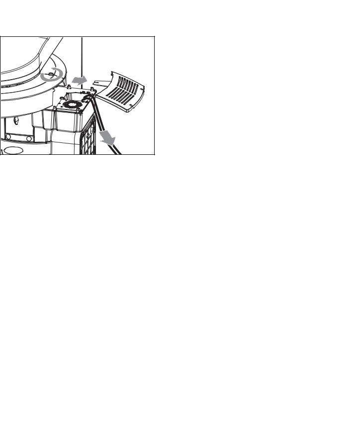
1.Remove cover (for details see Service Manual).
2.Remove the four screws A and remove cover plate B of the electronics box.
10 |
61 88 085 D3352 |
D3352.103.02.01.02 |
Schick Technologies, Inc. |
5 kV – verification, kV ramp during panoramic exposure |
Maintenance Instructions CDR PanElite
3. |
20VDC |
|
|
4. |
|
|
|
|
|
|
|
D |
|
|
com. |
|
|
|
|
C |
|
|
|
|
|
English |
|
|
KV– |
KV+ |
|
|
|
|
|
|
|
|
|
||
|
|
|
|
5. |
|
|
|
|
|
|
|
6. - 7. |
|
|
|
|
400 VDC |
n |
|
|
|
|
|
|
|
|
PC-board DX6 |
*o |
|
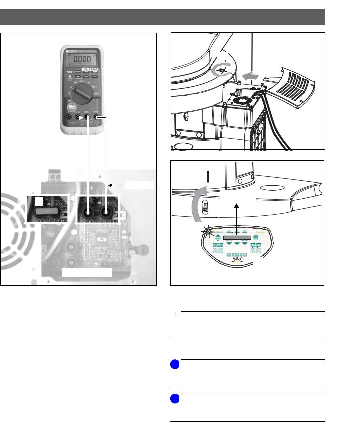
3.Connect digital voltmeter to KV+ and KV– test points on PC board DX6 and select range 20 VDC.
4.Refit cover C and tighten screw D securely.
5.Switch unit ON n.
Wait 1 min. for power on of the unit.
Press key R oto return X-ray tube head into the initial position.
6.Make sure that CDR PanElite Service program is ready to take an image.
7.Select P1 program and 62kV/8mA.
Measurement:
 CAUTION RADIATION
–Press and hold the exposure switch until the exposure terminates automatically.
The following values must be obtained
(see also diagram on next page)
•up to 5.25 seconds: 3.1 V ±0.3V
•from 6.25 to 7.85 s KV-ramp: e.g., 4 V ±0.4V
•after 8.85 seconds: 3 V ±0.3V
i NOTE
If specified values cannot be obtained, see Service Manual for troubleshooting.
61 88 085 D3352 |
11 |
D3352.103.02.01.02 |

5 kV – verification, kV ramp during panoramic exposure |
Schick Technologies, Inc. |
|
Maintenance Instructions CDR PanElite |
kV – Verification, kV–ramp during panoramic exposure
VDC |
|
|
|
|
|
|
|
|
|
|
|
|
|
|
|
|
|
|
|
|
|
|
|
|
|
|
|
|
|
|
|
|
|
|
|
|
|
|
|
|
|
|
|
|
|
|
|
|
|
|
|
|
|
|
|
|
|
||
9 |
|
|
|
|
|
|
|
|
|
|
|
|
|
|
|
|
|
|
|
|
|
|
|
|
|
|
|
|
|
|
|
|
|
|
|
|
|
|
|
|
|
|
|
|
|
|
|
|
|
|
|
|
|
|
|
|
|
|
|
|
|
|
|
|
|
|
|
|
|
|
|
|
|
|
|
|
|
|
|
|
|
|
|
|
|
|
|
|
|
|
|
|
|
|
|
|
|
|
|
|
|
|
|
|
|
|
|
|
|
|
|
|
|
|
|
|
|
|
|
|
|
|
|
|
|
|
|
|
|
|
|
|
|
|
|
|
|
|
|
|
|
|
|
|
|
|
|
|
|
|
|
|
|
|
|
|
|
|
|
|
|
|
|
|
|
|
|
|
|
|
|
|
|
|
|
|
|
|
|
|
|
|
|
|
|
|
|
|
|
|
|
|
|
|
|
|
|
|
|
|
|
|
|
|
|
|
|
|
|
|
|
|
|
|
|
|
|
|
|
|
|
|
|
|
|
|
|
|
|
|
|
|
|
|
|
|
|
|
|
|
|
|
|
|
|
|
|
|
|
|
7.05s |
|
|
|
|
|
|
|
|
|
|
|
|
|
|
|
|
|
|
|
|
|
|
|
|
|
14.1s |
|
|
|
|
|
|
|
|
|
|||||||||||||
|
|
|
|
|
|
|
|
|
|
|
|
|
|
|
|
|
|
|
|
|
|
|
|
|
|
|
|
|
|
|
|
|
|
|
|
|
|
|
|
|
|
|
|
|
|
||||||||||||||
8 |
|
|
|
|
|
|
|
|
|
|
|
|
|
|
|
|
|
|
|
|
|
|
|
|
|
|
|
|
|
|
|
|
|
|
|
|
|
|
|
|
|
|
Complete P1 |
|
|
|
|
|
|
||||||||||
|
|
|
|
|
|
|
|
|
|
|
|
|
|
|
|
|
|
|
|
|
|
|
|
|
|
|
|
|
|
|
|
|
|
|
|
|
|
|
|
|
|
exposure |
|
|
|
|
|
|
|
|
|
||||||||
|
|
|
|
|
|
|
|
|
|
|
|
|
|
|
|
|
|
|
|
|
|
|
|
|
|
|
|
|
|
|
|
|
|
|
|
|
|
|
|
|
|
|
|
|
|
|
|
|
|
|
|
||||||||
7 |
|
|
|
|
|
|
|
|
|
|
|
|
|
|
|
|
|
|
|
|
|
|
|
|
|
|
|
|
|
|
|
|
|
|
|
|
|
|
|
|
|
|
time |
|
|
|
|
|
|
|
|
|
|
|
|
||||
|
|
|
|
|
|
|
|
|
|
|
|
|
|
|
|
|
|
|
|
|
|
|
|
|
|
|
|
|
|
|
|
|
|
|
|
|
|
|
|
|
|
|
|
|
|
|
|
|
|
|
|
|
|
||||||
6 |
|
|
|
|
|
|
|
|
|
|
|
|
|
|
|
|
|
|
|
|
|
|
|
|
|
|
|
|
|
|
|
|
|
|
|
|
|
|
|
|
|
|
|
|
|
|
|
|
|
|
|
|
|
|
|
|
|
|
|
|
|
|
|
|
|
|
|
|
|
|
|
|
|
|
|
|
|
|
|
|
ramp |
|
|
|
|
|
|
|
|
|
|
|
|
|
|
|
|
|
|
|
|
|
|
|
|
|
|
|
|
|
|
|
|
||||||
5 |
|
|
|
|
|
|
|
|
|
|
|
|
|
|
|
|
|
|
|
|
|
1.6s |
|
|
|
|
|
|
|
|
|
|
|
|
|
ramp |
|
|
|
|
|
|
|
|
|
|
|
|
|
|
|
||||||||
|
|
|
|
|
|
|
|
|
|
|
|
|
|
|
|
|
|
|
|
|
|
|
|
|
|
|
|
|
|
|
|
|
|
|
|
|
|
|
|
|
|
|
|
|
|
|
|
|
|||||||||||
|
|
|
|
|
|
|
|
|
|
|
|
|
|
|
|
|
|
|
|
|
|
|
|
|
|
|
|
|
|
|
|
|
|
|
|
|
|
|
|
|
|
|
|
|
|
|
|
|
|
|
|
|
|
|
|||||
4 |
|
|
|
|
|
|
|
|
|
|
|
|
|
|
|
|
|
|
|
|
|
|
|
|
|
|
|
|
|
|
|
|
|
|
|
max. 4.05V |
|
|
|
Nominal 4.0V |
|
|
|
||||||||||||||||
|
|
|
|
|
|
|
|
|
|
|
|
|
|
|
|
|
|
|
|
|
|
|
|
|
|
|
|
|
|
|
|
|
|
|
|
|
|
|
|
|
|||||||||||||||||||
|
|
|
|
|
|
|
|
|
|
|
|
|
|
|
|
|
|
|
|
|
|
|
|
|
|
|
|
|
|
|
|
|
|
|
|
|
|
|
|
|
|
|
|
|
|
|
|
|
|
||||||||||
|
|
max. 3.41V |
|
|
|
|
|
|
|
|
|
|
|
|
|
|
|
|
|
|
|
|
|
|
|
|
|
|
|
min. 3.45V |
|
|
|
|
|
|
|||||||||||||||||||||||
Nominal 3.1V |
|
|
|
|
|
|
|
|
|
|
|
|
|
|
|
|
|
|
|
|
|
|
|
|
|
|
|
|
|
|
|
|
|
|
|
|
|
|
|
|
|
|
|
|
|||||||||||||||
3 |
|
|
|
min. 2.79V |
|
|
|
|
|
|
|
|
|
|
|
|
|
|
|
|
|
|
|
|
|
|
|
|
|
|
|
|
|
|
|
|
|
|
|
|
|
|
|
|
|
|
|
|
|
|
|
|
|
|
|||||
2 |
|
|
|
|
|
|
|
|
|
|
|
|
|
|
|
|
|
|
|
6.25s |
|
|
7.85s |
|
|
|
|
|
|
|
|
|
|
|
|
|
|
|
|
|
|
|
|
|
|
|
|
|
|||||||||||
|
|
|
|
|
|
|
|
|
|
|
|
|
|
|
|
|
|
|
|
|
|
|
|
|
|
|
|
|
|
|
|
|
|
|
|
|
|
|
|
|
|
|
|
|
|
|
|
|
|
|
|
|
|
|
|
|
|
|
|
|
|
|
|
|
|
|
|
|
|
|
|
|
5.25s |
|
|
|
|
|
|
|
|
|
|
|
|
|
8.85s |
|
|
|
|
|
|
|
|
|
|
|
|
|
|
|
|
|
|
|
|
|
|||||||||||
|
|
|
|
|
|
|
|
|
|
|
|
|
|
|
|
|
|
|
|
|
|
|
|
|
|
|
|
|
|
|
|
|
|
|
|
|
|
|
|
|
|
|
|
|
|
|
|
||||||||||||
1 |
|
|
|
|
|
|
|
|
|
|
|
|
|
|
|
|
|
|
|
|
|
|
|
|
|
|
|
|
|
|
|
|
|
|
|
|
|
|
|
|
|
|
|
|
|
|
|
|
|
|
|
|
|
|
|
|
|
|
|
|
|
|
|
|
|
|
|
|
|
|
|
|
|
|
|
|
|
|
|
|
|
|
|
|
|
|
|
|
|
|
|
|
|
|
|
|
|
|
|
|
|
|
|
|
|
|
|
|
|
|
|
|
|
|
|
|
|
|
|
|
|
|
|
|
|
|
|
|
|
|
|
|
|
|
|
|
|
|
|
|
|
|
|
|
|
|
|
|
|
|
|
|
|
|
|
|
|
|
|
|
|
|
|
|
|
|
|
|
|
|
|
|
|
|
|
|
|
||
|
|
|
|
|
|
|
|
|
|
|
|
|
|
|
|
|
|
|
|
|
|
|
|
|
|
|
|
|
|
|
|
|
|
|
|
|
|
|
|
|
|
|
|
|
|
|
|
|
|
|
|
|
|
|
|
|
|
|
|
0 |
|
1 |
2 |
3 |
|
4 |
|
5 |
|
|
6 |
7 |
|
|
8 |
|
|
|
9 |
10 |
11 |
|
12 |
13 |
14 |
15 |
s |
|
|||||||||||||||||||||||||||||||
|
|
|
|
|
|
|
|
|
|
|
|
|
|
|
|
|
|
|
|
|
|
|
|
|
|
|
|
|
|
|
|
|
|
|
|
|
|
|
|
|
|
|
|
|
|
|
|
|
|
|
|
|
|
|
|
|
|
|
|
Exposure time
kV ramp diagram
with program P1 and 62kV/8mA set on the Control Pad and temple support fully open.
12 |
61 88 085 D3352 |
D3352.103.02.01.02 |
Schick Technologies, Inc. |
5 kV – verification, kV ramp during panoramic exposure |
Maintenance Instructions CDR PanElite |
|
|
|
|
|
8. |
•Turn unit OFF.
8.Remove top cover and meter leads.
English
61 88 085 D3352 |
13 |
D3352.103.02.01.02 |

6 Tube Current Verification |
Schick Technologies, Inc. |
|
Maintenance Instructions CDR PanElite |
6 Tube Current Verification
 WARNING
The electronics of the X-ray tube assembly are always connected to line voltage.
Always switch the X-ray unit off and wait until V203 is no longer illuminated before contacting the test leads.
 WARNING
The test leads and measuring instruments used must have a dielectric strength of at least 1000V!
Be sure to use a battery-powered measuring instrument with shock-hazard-protected sockets.
Use only test leads with shock protection.
 WARNING
Be sure to switch the X-ray unit off before removing the jumper for the mA measuring jack.
14 |
61 88 085 D3352 |
D3352.103.02.01.02 |
Schick Technologies, Inc. |
6 Tube Current Verification |
Maintenance Instructions CDR PanElite
1. |
20VDC |
|
2. |
|
|
|
|
|
D |
|
com. |
|
|
C |
|
MA- |
400 VDC |
|
English |
|
MA+ |
|
|
|
|
|
|
3. |
|
|
A· |
|
n |
4. - 5. |
|
|
|
PC-board DX6 |
*o |
1.Remove shunt jumper A from MA+/MA – test points on PC board DX6. Connect digital multimeter to VDC and select range 20 mVDC.
2.Reattach cover C and tighten screw D securely.
3.Switch unit ON n.
Wait 1 min. for self-adjustment of the unit.
Press key R oto return X-ray tube head into the initial position.
4.Select 66kV/8mA. Make sure that CDR PanElite Service program is ready to take an image.
5.If P1 program and 66kV/8mA are selected . The unit must be ready for radiation.
Measurement:
 CAUTION RADIATION
– Press and hold the exposure switch until meter reading is obtained.
The multimeter shall indicate 8mV ±1.6mV. Record reading.
i NOTE
Readings: 1mV corresponds to a tube current of 1mA, tolerance +/-20%.
i NOTE
If specified values cannot be obtained, see Service Manual, chapter ”Tube Current Verification”.
61 88 085 D3352 |
15 |
D3352.103.02.01.02 |

6 Tube Current Verification |
Schick Technologies, Inc. |
|
Maintenance Instructions CDR PanElite |
|
|
|
|
6. |
•If specified value is obtained switch unit OFF.
6. Remove upper cover and meter leads
•Replace jumper!
16 |
61 88 085 D3352 |
D3352.103.02.01.02 |

Schick Technologies, Inc. |
7 Exposure Time Verification |
Maintenance Instructions CDR PanElite |
|
7 Exposure Time Verification
1. |
Pulse counter |
|
|
|
to N |
|
|
to L |
|
|
of 110VAC/60Hz |
|
|
power receptacle |
|
T1 |
T2 |
|
|
400 VDC |
2. |
D |
C |
English |
PC board DX6
 WARNING
The electronics of the X-ray tube assembly are always connected to line voltage.
Always switch the X-ray unit off and wait until V203 is no longer illuminated before contacting the test leads.
 WARNING
The test leads and measuring instruments used must have a dielectric strength of at least 1000V!
Be sure to use a battery-powered measuring instrument with shock-hazard-protected sockets.
1.Connect...
–test point T2 of terminal on PC board DX6 to L of 110V power receptacle
–the common lead of the pulse counter to N of the 110V power receptacle
–the second measuring lead of the pulse counter to test point T1
2.Refit cover C and tighten screw D securely.
Use only test leads with shock protection.
61 88 085 D3352 |
17 |
D3352.103.02.01.02 |

7 Exposure Time Verification
3. |
4. - 5. |
n |
*o |
3.Switch unit ON n.
Wait 1 min. for power on of the unit.
Press key R oto return X-ray tube head to the initial position.
4.Select 66kV/8mA.
Make sure that CDR PanElite Service program is ready to take an image.
Measurement:
 CAUTION RADIATION
– Press and hold the exposure switch until the exposure terminates automatically.
5.Select service routine S2 (Selecting a service routine: See Service Manual):
•Set radiation time to 1 sec.
• Measured values at 50 Hz 50 pulses +/-10%
•Measured values at 60 Hz 60 pulses +/-10%
Record average pulse count.
i NOTE
If specified value cannot be obtained, see Service Manual, chapter ”Exposure Time Verification”.
•If specified value is obtained, switch unit OFF.
6.Remove upper cover and meter leads.
18
Schick Technologies, Inc.
Maintenance Instructions CDR PanElite
6. |
61 88 085 D3352 D3352.103.02.01.02
Loading...