


 Loading...
loqelmelp=udmäìë=apL`ÉéÜ |
lйЙк~нбеЦ=fелнкмЕнбзел |
bеЦдблЬ |

General information |
Sirona Dental Systems GmbH |
|
Operating Instructions ORTHOPHOS XGPlus DS/Ceph |
General information
Dear customer, |
Thank you for purchasing your ORTHOPHOS XG Plus |
|
panoramic X-ray unit from Sirona. |
|
This system enables you to take standard views (jaw |
|
area), sinus views (maxillary sinuses) and temporoman- |
|
dibular joint views using digital imaging technology. |
|
If the system is equipped with a cephalometer arm, you |
|
can furthermore take cephalometric images using digital |
|
imaging technology. |
|
The technical documentation supplied is also part of |
|
the product. Keep these documents handy at all times |
|
(file in the X-ray logbook in Germany). |
|
To safeguard your warranty claims, please complete the |
|
attached “Installation Report/Warranty Passport” |
|
together with the service engineer immediately after the |
|
installation of your unit. |
|
Please familiarize yourself with the unit by reading |
|
through these Operating Instructions before taking |
|
any X-rays of patients. Always observe the valid |
|
radiation protection regulations and warnings. |
|
These operating instructions presuppose that you are |
|
familiar with the use of the SIDEXIS software. According |
|
to the X-ray Ordinance of the Federal Republic of |
|
Germany, owners of X-ray equipment must perform con- |
|
stancy tests at regular intervals in order to ensure the |
|
safety of operating staff and patients. |
|
Your ORTHOPHOS XG Plus Team |
Maintenance |
In the interest of the safety and health of patients, users |
|
and other persons, inspection and preventive mainte- |
|
nance must be performed at scheduled intervals to |
|
ensure the operational reliability and functional safety of |
|
your product (IEC 601-1/DIN EN 60601-1 etc.). |
|
The system owner must ensure that all inspections and |
|
maintenance events take place. |
|
If the system owner fails to fulfil the obligation to have |
|
inspections and maintenance work performed or ignores |
|
error messages, Sirona Dental Systems GmbH and its |
|
authorized dealers cannot assume any liability for result- |
|
ing damage. |
2 |
59 87 594 D 3352 |
D 3352.201.01.14.02 |

Sirona Dental Systems GmbH |
Contents |
Operating Instructions ORTHOPHOS XGPlus DS/Ceph |
|
Contents
1 |
Warning and safety information .............................................................................. |
5 |
|
|
1.1 |
General safety information................................................................................................................ |
5 |
|
1.2 |
ESD protective measures ................................................................................................................. |
9 |
|
1.3 |
About the physics of electrostatic charges ....................................................................................... |
9 |
2 |
Technical description ............................................................................................... |
11 |
||
3 |
Controls and functional elements ........................................................................... |
16 |
||
|
3.1 |
Operating and Display Elements ...................................................................................................... |
16 |
|
|
3.2 |
General touchscreen functions ......................................................................................................... |
19 |
|
4 |
Accessories ............................................................................................................... |
28 |
||
|
4.1 |
Rests and supports for panoramic exposures .................................................................................. |
28 |
|
|
4.2 |
Important when inserting the temporomandibular joint supports ...................................................... |
29 |
|
|
4.3 |
Protective covers for panoramic exposures...................................................................................... |
30 |
|
|
4.4 |
Protective covers for cephalometer .................................................................................................. |
31 |
|
|
4.5 |
Accessories for transversal slices TSA............................................................................................. |
31 |
|
5 |
Program group panoramic images.......................................................................... |
32 |
||
|
5.1 |
P1 |
Standard panoramic view, P1 A artifact-reduced, |
|
|
|
P1 |
C with a constant magnification factor of 1.25............................................................................. |
32 |
|
5.2 |
P2 normal view, limited to teeth without ascending rami, |
|
|
|
|
P2 |
A artifact-free, P2 C with a constant magnification factor of 1.25................................................ |
33 |
|
5.3 |
P10 normal view for children with significant dose reduction, |
|
|
|
|
P10 A artifact-free, P10 C with a constant magnification factor of 1.25............................................ |
34 |
|
|
5.4 |
P12 Slice thickness – anterior tooth region ...................................................................................... |
35 |
|
6 |
Program group temporomandibular joint (TMJ) views.......................................... |
36 |
||
|
6.1 |
TM1.1/TM1.2 Temporomandibular joints lateral with closed and open mouth in one image............ |
36 |
|
|
6.2 |
TM2.1/TM2.2 Temporomandibular joints in posterior – anterior projection with closed and |
|
|
|
|
open mouth in one image ................................................................................................................. |
37 |
|
|
6.3 |
TM3 Temporomandibular joints lateral, ascending rami................................................................... |
38 |
|
|
6.4 |
TM4 Temporomandibular joints in posterior/anterior projection ....................................................... |
39 |
|
|
6.5 |
TM5 Temporomandibular joints lateral, multislice ............................................................................ |
40 |
|
|
6.6 |
TM6 Temporomandibular joints, multislice in posterior - anterior projection .................................... |
41 |
|
7 |
Program group sinus views ..................................................................................... |
42 |
||
|
7.1 |
S1 |
Paranasal sinuses ....................................................................................................................... |
42 |
|
7.2 |
S2 |
Maxillary sinuses with two views in one image ........................................................................... |
43 |
|
7.3 |
S3 |
Paranasal sinuses (linear slice orientation)................................................................................. |
44 |
|
7.4 |
S4 |
Maxillary sinuses with two views in one image (linear slice orientation) ..................................... |
45 |
8 |
Program group multislice views .............................................................................. |
46 |
||
|
8.1 |
MS1 Multislice (posterior tooth region) ............................................................................................. |
46 |
|
aЙмнлЕЬ
59 87 594 D 3352 |
3 |
D 3352.201.01.14.02 |
Contents |
Sirona Dental Systems GmbH |
|
Operating Instructions ORTHOPHOS XGPlus DS/Ceph |
9 |
Operation .................................................................................................................... |
47 |
|
|
9.1 |
Preparing the exposure.................................................................................................................... |
47 |
|
9.2 |
Option: Execution of exposures from a SIDEXIS exposure template .............................................. |
50 |
|
9.3 |
Positioning the patient...................................................................................................................... |
51 |
|
9.4 |
Finishing the preparations (panoramic views) ................................................................................. |
58 |
|
9.5 |
Making the basic settings in program level 3 ................................................................................... |
59 |
|
9.6 |
Changing the startup settings in program level 4............................................................................. |
59 |
|
9.7 |
Selecting the exposure parameters ................................................................................................. |
60 |
|
9.8 |
Releasing the exposure ................................................................................................................... |
61 |
|
9.9 |
Remote control................................................................................................................................. |
63 |
10 |
Cephalometric exposures (CEPH)............................................................................ |
64 |
|
|
10.1 |
Preparing a cephalometric exposure (CEPH function) .................................................................... |
64 |
|
10.2 |
Preparations on the cephalometer................................................................................................... |
66 |
|
10.3 |
Positioning a ceph patient................................................................................................................ |
67 |
|
10.4 |
Select exposure data ....................................................................................................................... |
74 |
|
10.5 |
Making the basic settings in program level 3 ................................................................................... |
75 |
|
10.6 |
Changing the startup settings in program level 4............................................................................. |
75 |
|
10.7 |
Releasing a cephalometric exposure............................................................................................... |
76 |
11
12
13
14
15
Transversal slices (TSA) ........................................................................................... |
79 |
|
11.1 |
Preparing a TSA exposure............................................................................................................... |
79 |
11.2 |
Patient positioning............................................................................................................................ |
86 |
11.3 |
TSA universal bite block .................................................................................................................. |
90 |
11.4 |
Preselecting the exposure settings and releasing the exposure...................................................... |
92 |
11.5 |
Program settings, basic settings, startup settings............................................................................ |
93 |
11.6 |
TSA exposure with TSA slice orientation......................................................................................... |
94 |
11.7 |
Slice orientations.............................................................................................................................. |
96 |
Program values .......................................................................................................... |
98 |
|
12.1 |
Panoramic views – program values for index 2A............................................................................. |
98 |
12.2 |
Panoramic views – program values for index 4A............................................................................. |
99 |
12.3 |
Panoramic views – program values for index 1A............................................................................. |
100 |
12.4 |
Program values for cephalometric exposures.................................................................................. |
101 |
12.5 |
TSA exposure values....................................................................................................................... |
102 |
List of messages ........................................................................................................ |
105 |
|
13.1 |
List of help messages ...................................................................................................................... |
105 |
13.2 |
Error message structure .................................................................................................................. |
106 |
Care of outer surfaces ............................................................................................... |
108 |
|
Inspection and maintenance..................................................................................... |
109 |
|
15.1 |
Annual check performed by the system owner or other authorized persons ................................... |
109 |
15.2 |
Maintenance by the service engineer .............................................................................................. |
109 |
15.3 |
Image quality check ......................................................................................................................... |
109 |
16 |
Activating functions................................................................................................... |
110 |
|
|
16.1 |
Via the Easypad touchscreen .......................................................................................................... |
110 |
|
16.2 |
Via web browser on the PC ............................................................................................................. |
112 |
4 |
59 87 594 D 3352 |
D 3352.201.01.14.02 |

Sirona Dental Systems GmbH |
1 Warning and safety information |
Operating Instructions ORTHOPHOS XGPlus DS/Ceph |
1.1 General safety information |
1 Warning and safety information
1.1 |
General safety information |
|
Identification of warning and safety information |
To prevent any personal injury or material damage, |
|
|
|
please observe the warning and safety information pro- |
|
|
vided in the present operating instructions. All such infor- |
|
|
mation is highlighted by the signal words NOTE, |
|
|
ATTENTION or WARNING. |
Symbols used |
Observe accompanying documents |
|
|
|
(on rating plate) |
Intended use |
This system is intended for generating panoramic or |
|
|
|
cephalometric X-ray images. |
|
|
This system must not be used in areas subject to explo- |
|
|
sion hazards. |
Maintenance and repair |
As manufacturers of medical electrical equipment we |
|
|
|
can assume responsibility for the safety-related features |
|
|
of the equipment only if maintenance and repair are |
|
|
carried out only by ourselves or agencies expressly |
|
|
authorized by us, and if components affecting safe oper- |
|
|
ation of the system are replaced with original spare |
|
|
parts upon failure. |
|
|
We suggest that you request a certificate showing the |
|
|
nature and extent of the work performed from those who |
|
|
carry out such work; it must contain any changes in rated |
|
|
parameters or working ranges (if applicable), as well as |
|
|
the date, the name of the company and a signature. |
Modifications to the system |
Modifications to this system which might affect the safety |
|
|
|
of the system owner, patients or other persons are pro- |
|
|
hibited by law! |
|
|
For reasons of product safety, this product may be |
|
|
operated only with original Sirona accessories or |
|
|
third-party accessories expressly approved by Sirona. |
|
|
The user assumes the risk of using non-approved |
|
|
accessories. |
Combination with other equipment |
Permissible combinations are specified in the |
|
|
|
Declaration of Conformity by the system integrator. |
|
|
The Declaration of Conformity is included in the techni- |
|
|
cal documentation. |
Ventilation slots |
Under no circumstances may the ventilation slots on the |
|
|
|
unit be covered, since otherwise the air circulation will be |
|
|
obstructed. |
Do not spray disinfectants or other similar products into the ventilation slots.
English
59 87 594 D 3352 |
5 |
D 3352.201.01.14.02 |
1 Warning and safety information |
Sirona Dental Systems GmbH |
1.1 General safety information |
Operating Instructions ORTHOPHOS XGPlus DS/Ceph |
X-rays of patients |
X-rays of patients must be taken only when the system |
|
works without errors. |
|
The system may only be operated by skilled or prop- |
|
erly trained personnel. |
|
The movements of the unit must not be obstructed by |
|
physical constitution nor clothing, dressings, wheel- |
|
chairs or hospital beds! |
|
Do not leave the patient unattended in the unit. |
Electromagnetic compatibility (EMC) |
Medical electrical equipment is subject to special pre- |
|
cautionary measures regarding EMC. It must be |
|
installed and operated as specified in the document |
|
“Installation Requirements”. |
|
Information on avoiding, detecting and eliminating unin- |
|
tended electromagnetic effects: The ORTHOPHOS |
|
XGPlus DS/Ceph acquisition unit is Class B equipment |
|
(classified according to CISPR 11, EN 60601-1-2: 2001 |
|
based on IEC 60601-1-2). This system may be operated |
|
in a residential area. |
|
Portable and mobile RF communications equipment |
|
may interfere with medical electrical equipment. There- |
|
fore, the use of mobile wireless phones in practice or |
|
hospital environments must be prohibited. |
|
Please also observe the ESD protective measures in |
|
Chapter 1.2. |
Removing the sensor |
To remove the sensor, hold it firmly, press the pushbutton |
|
fully in and hold it down. Remove the sensor from its |
|
holder by pulling it downward. |
|
DO NOT DROP THE SENSOR! |
Precautionary measures when switching on the unit
A shock sensor for detecting shocks or dropping is built in.
When removing the sensor, and also with an already removed sensor, make sure not to touch the sensor plug on the unit end, especially not while touching the patient at the same time.
Following extreme changes in temperature, condensation may occur; therefore, please do not switch the system on until it has reached normal room temperature (see chapter “Technical description”).
No patient may be positioned in the unit during power-on.
In case of an error that requires switching the unit off and back on again, the patient must be removed from the unit, at the latest before switching the unit on again!
6 |
59 87 594 D 3352 |
D 3352.201.01.14.02 |
Sirona Dental Systems GmbH
Operating Instructions ORTHOPHOS XGPlus DS/Ceph
Emergency Stop
Disturbance of electronic devices worn on the patient’s body
Radiation protection
Hygiene information
Dismantling and reassembly
59 87 594 D 3352
D 3352.201.01.14.02
1 Warning and safety information
1.1 General safety information
If any parts of the unit happen to touch the patient during |
|
the rotary movement (PAN exposure) or during the scan |
|
movement (cephalometric exposure), let go of the expo- |
English |
data storage devices, e.g. radio-controlled watches, |
|
sure release button (X-Ray) immediately or stop the unit |
|
by actuating the unit main switch or an Emergency Stop |
|
switch! |
|
To prevent the malfunctioning of electronic devices and |
|
telephone cards, etc., these objects must be removed |
|
prior to X-raying. |
|
The valid radiation protection regulations must be |
|
observed. |
|
The operator should move as far away from the X-ray |
|
tube assembly as allowed by the coiled cable of the |
|
exposure release button. |
|
The statutory radiation protection equipment must be |
|
used. |
|
With the exception of the patient, no other persons |
|
without radiation protection are allowed to stay in the |
|
room. In exceptional cases, a third person may provide |
|
assistance, but not the practice staff. During the whole |
|
exposure, visual contact with the patient and the unit |
|
must be maintained. |
|
In case of malfunctions, cancel the exposure immedi- |
|
ately by letting go of the exposure release button. |
|
The protective covers must be exchanged and the ster- |
|
ilizable accessories must be resterilized for each new |
|
patient to prevent any transmission of infective agents |
|
which might cause serious illnesses. |
|
Suitable hygienic measures must be taken to prevent |
|
cross contamination among patients, users and other |
|
persons. |
|
When dismantling and reassembling the system, pro- |
|
ceed according to the installation instructions for new |
|
installation in order to guarantee its proper functioning |
|
and stability. |
|
7
1 Warning and safety information |
Sirona Dental Systems GmbH |
1.1 General safety information |
Operating Instructions ORTHOPHOS XGPlus DS/Ceph |
Disposal
Laser light localizer used
It generally applies that any disposal of this product must comply with the relevant national regulations. Please observe the regulations applicable in your country.
Within the European Economic Community, Council Directive 2002/96/EU (WEEE) requires environmentally sound recycling/disposal of electrical and electronic devices.
Your product is marked with the adjacent symbol. Disposal of your product with domestic
refuse is not compatible with the objectives of environmentally sound recycling/disposal.
The black bar underneath the "garbage can" symbol means that it was put into circulation after Aug. 13, 2005 (see EN 50419:2005).
Please note that this product is subject to Council Directive 2002/96/EU (WEEE) and the applicable national law of your country and must be recycled or disposed of in an environmentally sound manner.
The X-ray tube assembly of this product contains a tube with a potential implosion hazard, a small amount of beryllium, a lead lining and mineral oil.
The unit contains counterbalancing weights made of lead.
Please contact your dealer if final disposal of your product is required.
The system incorporates Class 1 laser products.
The light localizers are intended for correct patient positioning. They must not be used for any other purposes.
A minimum distance of 100mm between the eye and the laser is required. Do not stare into the beam. Safe operation is described in chapter “9.3 Positioning the patient”.
The light localizers must be switched on only when they work properly and without errors. Repair work must be carried out by authorized staff only.
8 |
59 87 594 D 3352 |
D 3352.201.01.14.02 |
Sirona Dental Systems GmbH |
1 Warning and safety information |
Operating Instructions ORTHOPHOS XGPlus DS/Ceph |
1.2 ESD protective measures |
1.2 ESD protective measures
ESD stands for ElectroStatic Discharge.
 ATTENTION
Connector pins or sockets bearing ESD warning labels must not be touched or interconnected without ESD protective measures.
ESD protective measures include:
• Procedures for preventing electrostatic charge build-up (e.g. air conditioning, air moistening, conductive floor coverings and non-synthetic clothing).
• Discharging the electrostatic charges of your own body on the frame of the UNIT, the protective ground wire or large metallic objects.
• Connecting yourself to ground using a wrist band.
We therefore recommend that all persons working with this system be instructed on the significance of this warning label. Furthermore, they also should receive training in the physics of electrostatic discharges which can occur in the practice and the destruction of electronic components which may result if such components are touched by electrostatically charged USERS.
The content of this training is explained in Chapter 1.3.
1.3 About the physics of electrostatic charges
ESD stands for ElectroStatic Discharge. Electrostatic discharge must be preceded by electrostatic charging.
Static electric charges generally build up whenever two bodies are rubbed against each other, e.g. when walking (shoe soles against the floor) or driving a vehicle (tires against the street pavement). The amount of charge depends on several factors:
Thus the charge is higher in an environment with low air humidity than in one with high air humidity; it is also higher with synthetic materials than with natural materials (clothing, floor coverings).
The following rule of thumb can be applied to assess the transient voltages resulting from an electrostatic discharge.
An electrostatic discharge is:
• perceptible at 3,000 V or higher
English
59 87 594 D 3352 |
9 |
D 3352.201.01.14.02 |

1 Warning and safety information
1.3 About the physics of electrostatic charges
1 nanosecond = 1/1.000.000,000 second =
1 billionth of a second
10
Sirona Dental Systems GmbH
Operating Instructions ORTHOPHOS XGPlus DS/Ceph
•audible at 5,000 V or higher (cracking, crackling)
•visible at 10,000 V or higher (arc-over)
The transient currents resulting from these discharges have a magnitude of 10 amperes. They are not hazardous for humans because they last for only several nanoseconds.
Voltage differentials exceeding 30,000 volts per centimeter may lead to a charge transfer (electrostatic discharge, lightning, arc-over).
Integrated circuits (logical circuits and microprocessors) are used in order to implement a wide variety of functions in dental/X-ray/CEREC systems. The circuits must be miniaturized to a very high degree in order to include as many functions as possible on these chips. This leads to structure thicknesses as low as a few ten thousandths of a millimeter.
It is obvious that integrated circuits which are connected to plugs leading outside of the unit via cables are sensitive to electrostatic discharge. Even voltages which are imperceptible to the user can cause breakdown of the structures, thus leading to a discharge current which melts the chip in the affected areas. Damage to individual integrated circuits may cause malfunction or failure of the system.
To prevent this from happening, the ESD warning label next to the plug warns of this hazard.
59 87 594 D 3352 D 3352.201.01.14.02
Sirona Dental Systems GmbH |
2 Technical description |
Operating Instructions ORTHOPHOS XGPlus DS/Ceph |
|
2 Technical description
Model designation: |
ORTHOPHOS XGPlus DS/Ceph |
Nominal voltage: |
200 – 240 V |
Permissible deviation: |
± 10 % |
Permissible drop under load: |
10 % |
Rated current: |
12 A |
Nominal power output: |
2 kW at 90 kV/12 mA with any radiation time |
Nominal frequency: |
50/60 Hz |
Internal line impedance: |
max. 0.8 Ohm |
Main building fuse: |
25 A slow-blow (16 A for standalone connection) |
Power consumption: |
2 kVA |
Power output of tube assembly: |
90 kV/12 mA = 1080 W with any radiation time |
Tube voltage: |
60 – 90 kV (for 90 kV max. 12 mA) |
Tube current: |
3 – 16 mA (at 16 mA max. 66 kV) |
Maximum setting range: |
60 kV/3 mA to 90 kV/12 mA |
High-voltage waveform: |
High-frequency multipulse |
|
Residual ripple ≤ 4 kV |
Program duration: |
see chapter 12 |
Exposure time: |
see chapter 12 |
Image acquisition scale: |
For P1, normal dental arch (slice center) approx. 1:1.19, |
|
i.e. the acquired image is magnified by approx. 19 % on aver- |
|
age compared to reality |
Exposure time for cephalometry: |
max. 14.9 s |
Total filtration of X-ray tube assembly: |
> 2.5 Al/90 IEC 522 1976 |
Focal spot size acc. to IEC 336, |
|
measured in the central X-ray beam: |
0.5 mm |
Marking of focal spot: |
|
English
59 87 594 D 3352 |
11 |
D 3352.201.01.14.02 |
2 Technical description
Automatic exposure blocking (see page 46):
Class I device
Degree of protection against electric shock: Degree of protection against ingress of water:
Year of manufacture:
Mode of operation:
Long-term power output:
Anode material:
Exposure parameters for determining leakage radiation:
Transport and storage temperature: Air humidity:
Admissible operating temperature:
Panoramic exposures:
Sensor (image receptor):
Pan sensor type:
Active sensor area, Pan type:
Detail resolution:
Focus/sensor distance:
Cephalometric exposures:
Sensor (image receptor):
Ceph sensor type:
Active sensor area, Ceph type:
Detail resolution:
Focus-sensor distance:
12
Sirona Dental Systems GmbH
Operating Instructions ORTHOPHOS XGPlus DS/Ceph
The duration of automatic exposure blocking (cooling period) depends on the set kV/mA level and the actual exposure time. Depending on the tube load, a pause duration of 8 s to 300 s is automatically set by the system.
Example: For program P1 with 80 kV/14 mA as exposure parameters and a radiation time of 14.1 s, the resulting pause duration is 255 s.
Type B equipment
Ordinary device
(without protection against ingress of water)
(on the rating plate)
Continuous operation
100 W
Tungsten
1.1 mA/90 kV
-10 °C – +70 °C (14 °F – 158 °F)
10 % – 95 %
Acc. to IEC 601-1 between +10 °C and +40 °C (50 °F – 104 °F)
Digital CCD line sensor, pluggable for panoramic exposure technique
138 x 6.48 mm
0.027 mm pixel size
497 mm
Digital CCD line sensor, pluggable for panoramic or ceph exposure technique
230 mm x 6.48 mm
0.027 mm pixel size
1.714 mm
59 87 594 D 3352 D 3352.201.01.14.02

Sirona Dental Systems GmbH |
2 Technical description |
Operating Instructions ORTHOPHOS XGPlus DS/Ceph |
|
TSA exposure:
Sensor (image receptor):
TSA senor type:
Active sensor area, TSA type
Detail resolution:
Focus-sensor distance:
X-ray tube:
Minimum requirements for PC systems:
Hard disk:
RAM:
Drives:
Operating system:
Graphics system:
Network:
Communication interface:
Digital CCD line sensor, pluggable for panoramic or ceph exposure technique
60 mm x 20 mm
0.0195 mm pixel size
497 mm
SR 90/15 from Siemens or
OCX 100 CEI
>4 GB/database
>50 MB/SIDEXIS installation
min. 256 MB
CD-ROM
MOD drive, min. 640 MB (once per system/network)
Minimum requirement: Windows 2000 Workstation (SP 4), Windows XP Professional Workstation (SP 2) or Vista. Additional information is available on the Sidexis website, www.sidexis.com, or in the Sidexis Operator's Manual.
Min. resolution 1024 x 768 pixels, min. color depth 8 bits
10/100 MBit Ethernet
RJ45 for LAN cable
ORTHOPHOS XGPlus DS/Ceph complies with IEC 601-2-28/1993
ORTHOPHOS XGPlus DS/Ceph complies with IEC 601-1-3/1994
ORTHOPHOS XGPlus DS/Ceph complies with IEC 601-2-7/1998
ORTHOPHOS XGPlus DS/Ceph complies with AS/NZS 3200.1.0
Original language: |
|
|
German |
||||
Reg. No.: China |
|
|
SFDA (I) 20053301583 |
||||
|
|
|
|
|
|
|
This product bears the CE mark in accordance with |
|
|
|
|
||||
|
|
|
|
|
|
|
the provisions of Council Directive 93/42/EEC of |
|
|
|
|
|
|
|
|
|
|
|
|
|
|
|
June 14, 1993 concerning medical devices. |
|
|
|
|
|
|
|
|
|
0123 |
|
|||||
|
|
|
|
|
|
|
Cooling curve of tube housing |
59 87 594 D 3352 |
13 |
||||||
D 3352.201.01.14.02 |
|||||||
English

2 Technical description |
Sirona Dental Systems GmbH |
|
Operating Instructions ORTHOPHOS XGPlus DS/Ceph |
|
HUx104 |
|
1 HU = 1.35 Joule |
|
|
|
|
|
|
|
|
|
|
|
|
|||
130 |
|
|
|
|
|
|
|
|
|
|
|
|
|
|
|
|
|
|
120 |
|
|
|
|
|
|
|
|
|
|
|
|
|
|
|
|
|
|
110 |
|
|
|
|
|
|
|
|
|
|
|
|
|
|
|
|
|
|
100 |
|
|
|
|
|
|
|
|
|
|
|
|
|
|
|
|
|
|
90 |
|
|
|
|
|
|
|
|
|
|
|
|
|
|
|
|
|
|
80 |
|
|
|
|
|
|
|
|
|
|
|
|
|
|
|
|
|
|
70 |
|
|
|
|
|
|
|
|
|
|
|
|
|
|
|
|
|
|
60 |
|
|
|
|
|
|
|
|
|
|
|
|
|
|
|
|
|
|
50 |
|
|
|
|
|
|
|
|
|
|
|
|
|
|
|
|
|
|
40 |
|
|
|
|
|
|
|
|
|
|
|
|
|
|
|
|
|
|
30 |
|
|
|
|
|
|
|
|
|
|
|
|
|
|
|
|
|
|
20 |
|
|
|
|
|
|
|
|
|
|
|
|
|
|
|
|
|
|
10 |
|
|
|
|
|
|
|
|
|
|
|
|
|
|
|
|
t |
|
0 |
60 |
|
120 |
180 |
240 |
300 |
360 |
420 |
480 |
540 |
|
600 |
660 |
720 |
|
min |
|
|
|
|
|
|
|
|
|
|
|
|
|
Abkühlkurve der Röntgenröhre |
|||||||
SR 90/15 |
|
|
|
|
|
|
OCX 100 |
|
|
|
|
|
|
|
|
|||
|
|
|
|
|
|
|
|
|
30 |
HUx103 |
1HU = 1,35 Joule |
|
|
|
||||
|
|
|
|
|
|
|
|
|
|
|
|
|
|
|
|
|
|
|
25 |
HUx103 |
|
1HU = 1,35 Joule |
|
|
25 |
|
|
|
|
|
|
|
|
|
|||
|
|
|
|
|
|
|
|
|
|
|
|
|
|
|
|
|
||
20 |
|
|
|
|
|
|
|
|
20 |
|
|
|
|
|
|
|
|
|
15 |
|
|
|
|
|
|
|
|
15 |
|
|
|
|
|
|
|
|
|
10 |
|
|
|
|
|
|
|
|
10 |
|
|
|
|
|
|
|
|
|
5 |
|
|
|
|
|
|
|
|
5 |
|
|
|
|
|
|
|
|
|
|
|
|
|
|
|
|
t |
|
|
|
|
|
|
|
|
|
|
t |
0 |
1 |
2 |
3 |
4 |
5 |
6 |
min |
|
0 |
1 |
2 |
3 |
4 |
5 |
6 |
7 |
8 |
min |
Heating curve of tube housing
|
HUx104 |
|
1 HU = 1.35 Joule |
|
|||
130 |
|
|
|
|
|
|
|
|
|
|
|
|
|
|
t |
0 |
1 |
2 |
3 |
4 |
5 |
6 |
h |
Central X-ray beam/anode angle
Central X-ray beam
Anode angle
14 |
59 87 594 D 3352 |
D 3352.201.01.14.02 |
Sirona Dental Systems GmbH |
2 Technical description |
Operating Instructions ORTHOPHOS XGPlus DS/Ceph |
|
These operating instructions are valid for the basic and full versions of the system.
The following programs and functions are included in the basic version:
10 panoramic programs:
P1, P1 A, P1 C, P2, P10 P1 L, P1 R
P12
TM1.1/TM1.2
TM2.1/TM2.2
S1
S2
MS1
5 Ceph programs:
C1, C2, C3, C3 F, C4
Half-views of right/left side possible only with P1 (not upper/lower jaw).
The full version offers the following programs and functions in addition to those featured in the basic version:
Additional pan programs:
Constant magnfication factor of 1.25 P2 C, P10 C Artifact-free display P2 A, P10 A
Selectable right/left side image detail and individual quadrants P1A/C, P 2/A/C, P10/A/C Image detail selectable upper jaw/lower jaw and single quadrants P1A/C, P2/A/C, P10/A/C Selectable upper jaw/lower jaw image detail P12
Temporomandibular joint views TM3, TM4, TM5, TM6 Sinus views S3, S4
Program setting for “jaw shape” selectable.
Quickshot function possible (for Pan P1, P2, P10 and Ceph C1 to C4).
Execution of exposure templates from SIDEXIS possible without cooling periods, e.g.: orthodontic image series P1 - C3 - C4.
Welcome screen with patient data from SIDEXIS.
Ceph – no shadowing in the upper cranial region preselectable for programs C3 and C3 F. Ceph – shadowing in the thyroid area for programs C1 and C2 can be preselected.
Option for basic version and full version:
TSA function (transversal slices)
It is possible to upgrade a basic version system to a full version system and/or to include the TSA function.
A certificate with a corresponding activation key number must be purchased for this purpose (see chapter 16). If the unit is ordered with TSA ex works, TSA will be activated at the factory.
English
59 87 594 D 3352 |
15 |
D 3352.201.01.14.02 |
3 Controls and functional elements |
Sirona Dental Systems GmbH |
3.1 Operating and Display Elements |
Operating Instructions ORTHOPHOS XGPlus DS/Ceph |
3 Controls and functional elements
3.1 Operating and Display Elements
1 |
2 |
3 |
4 |
5 |
6 |
7 |
8 |
9 |
|
|
|
CEPH TS TS |
|
|
|
|
|
|
|
64 |
|
|
|
|
|
|
|
|
|
64kV |
|
|
|
|
|
|
|
T R |
8mA |
|
|
|
|
|
|
|
ORTHOPHOS ist aufnahmebereit |
? |
|
|
|
|
|
10 |
11 12 |
|
13 |
14 15 16 17 |
|
|||
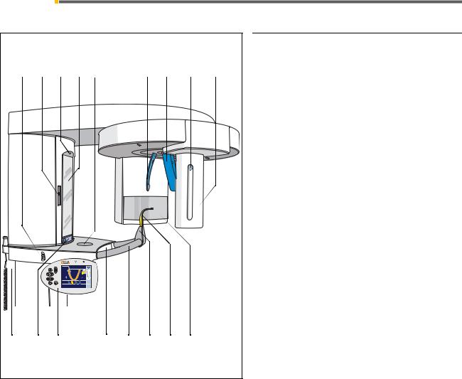
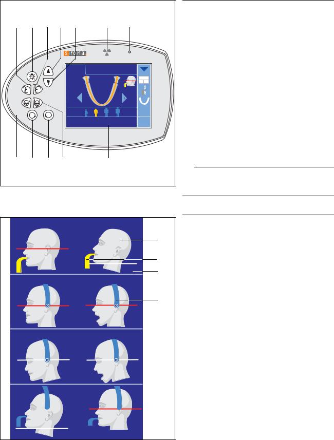
on the Panoramic unit
1.Main switch
2.Light localizer with height adjustment of FH light line
3.Light localizer central light beam for face center
4.Control mirror for patient positioning
5.Tray for jewelry, etc.
6.Forehead support
7.Temple supports
8.Pushbutton for sensor (image receptor) removal
9.Sensor (image receptor), depending on unit version: for XG Pan
for XG Ceph for XG Pan/TSA
for XG Ceph/TSA
10.Exposure release button (must be pressed and held down during the entire exposure)
11.Touch bar for swiveling the control mirror in and out
12.Easypad (swivelable control panel)
13.Drawer for accessories
14.Handles for patient
15.Holder for chin rest, bite blocks or contact segments etc.
16.Bite block, contact segment or chin rest
17.Primary diaphragm field on the X-ray tube assembly
16 |
59 87 594 D 3352 |
D 3352.201.01.14.02 |

Sirona Dental Systems GmbH |
3 Controls and functional elements |
Operating Instructions ORTHOPHOS XGPlus DS/Ceph |
3.1 Operating and Display Elements |
18 |
19 |
20 |
|
|
21 |
|
|
22 |
|
|
|||||
|
|
60 |
70 |
80 |
90 |
100 |
110 |
120 |
|
|
|
|
|
|
|
|
|
|
|
|
|
|
|
|
|
|
|
||||
23 |
|
|
|
|
|
|
|
|
|
|
|
|
|
|
|
8 |
40 |
|
|
|
|
|
|
|
|
|
|
|
|
|
|
50 |
|
|
|
|
|
|
|
|
|
|
|
|
|
|
|
|
|
|
|
|
|
|
|
|
|
|
|
|
|
|
|
24 |
|
|
|
|
|
|
|
|
|
|
|
|
|
|
|
|
|
25 |
|
|
25 |
|
|
|
|
|
|
||||
26 |
|
|
|
|
|
|
|
|
|
|
|
|
|
|
|
|
|
|
|
|
|
|
|
|
9 |
|
|
|
|
|
|
|
|
|
|
|
|
|
|
|
60 |
70 |
80 |
90 |
100 |
110 |
120 |
8 |
|
|
|
|
|
|
|
|
|
|
|
|
|
|
|
|
|
|
|
|
|
|
|
|
|
|
20 |
|
|
|
|
|
|
|
|
|
23 |
20 |
|
|
|
|
|
|
|||
|
|
|
|
|
30 |
|
|
|
|
|
|
||||
|
|
|
|
|
40 |
|
|
|
|
|
|
||||
|
|
|
|
|
|
|
|
|
50 |
|
|
|
|
|
|
|
|
|
|
|
|
|
|
|
24 |
|
|
|
|
|
|
59 87 594 D 3352 |
|
|
|
|
|
|
|
|
|
|
|
|
|
|
|
D 3352.201.01.14.02 |
|
|
|
|
|
|
|
|
|
|
|
|
|
|
|
Controls and scales on the cephalometer
8.Pushbutton for sensor removal
9.Sensor (image receptor)
18.Nose support
19.Locking knob for nose support
20.Scale for horizontal nose support adjustment
21.Rotating element for rotary movement of head supports
22.Secondary diaphragm with FH line light localizer
23.Scale for vertical nose support adjustment
24.Projection scale
25.Ear plugs with holders
26.Carpus support plate
Magnification of the lateral view
With this exposure technique, a metal scale (24) integrated in the nose support is displayed on the X-ray exposure.
Using this scale, the magnification factor in the median plane can be determined precisely via a measurement.
 ATTENTION
Never support yourself on the cephalometer or the ceph arm, hang objects from them or place objects on them. Otherwise their adjustment may be altered, thus resulting in incorrect images.
17
English
3 Controls and functional elements |
Sirona Dental Systems GmbH |
3.1 Operating and Display Elements |
Operating Instructions ORTHOPHOS XGPlus DS/Ceph |
27 |
28 29 30 31 |
32 |
33 |
|
|
|
|
|
CEPH TS |
|
|
|
|
|
P1 |
|
|
|
|
10 |
|
|
|
|
|
|
|
|
64kV |
|
T |
R |
|
|
8mA |
|
|
|
|
||
|
|
ORTHOPHOS is ready for exposure |
? |
||
34 |
35 |
36 37 |
38 |
|
|
P1, P2, P10, P12 |
MS1 |
|
|
||
|
|
|
|
|
A |
|
|
|
|
|
B |
|
|
|
|
|
C |
TM1.1, TM3, TM5 |
TM1.2 |
|
|
||
|
|
|
|
|
D |
TM2.1, TM4, TM6 |
TM2.2 |
|
|
||
S1 |
|
|
S2 |
|
|
18 |
|
|
|
|
|
Controls and displays on the Easypad with touchscreen
27.“Move forehead support away from forehead” key
28.Light localizers ON/OFF
29.“Move forehead support to forehead” key
30.“Unit up” arrow key
31.“Unit down” arrow key
32.Optical radiation indicator
33.“Unit ON” LED
34.“Open temple supports” key
35.“T” key for test cycle without radiation
36.“R” key for return of the unit
37.“Close temple supports” key
38.Touchscreen – touch-sensitive screen
 ATTENTION
Never touch the touchscreen with sharp or pointed objects (ball-point pens, pencils, etc.)!
Display aids for patient head positioning
The icon for the patient's head that is displayed in the upper right corner for panoramic and TSA images will guide you in positioning the patient's head.
AThe gray patient's head icon shows the head posture: straight (FH), bent forward with open or closed mouth, or reclined.
BA colored symbol (yellow or blue) will indicate if a bite block or a contact segment should be used.
CThe red line indicates the reflecting light localizer line (FH), the white line is only an auxiliary line to indicate the head inclination.
DFor temporomandibular joint and sinus views, the temporomandibular joint support is also displayed in blue.
If a small circle with a dot in its center appears at the end of the support, ear holders must be inserted; only contact pads are required if this symbol is not displayed.
59 87 594 D 3352 D 3352.201.01.14.02
Sirona Dental Systems GmbH |
3 Controls and functional elements |
Operating Instructions ORTHOPHOS XGPlus DS/Ceph |
3.2 General touchscreen functions |
3.2 General touchscreen functions
1 |
2 |
3 |
4 |
5 |
6 |
3 |
7 |
8 |
9 |
|
PAN |
CEPH |
TS |
|
|
|
|
||
|
|
|
|
P1 |
|
|
|
|
|
10 |
|
|
|
|
|
|
|
|
|
|
|
|
|
Quick |
|
|
|
|
|
|
|
|
|
|
|
|
|
64kV |
|
|
|
|
|
|
|
|
|
8mA |
|
ORTHOPHOS is ready for exposure |
|
? |
|
||||||
10 11 12 13 |
|
18 14 15 |
16 17 |
|
19 |
||||
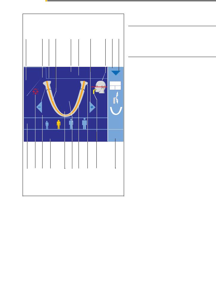
Touchscreen = touch-sensitive screen, i.e. touching the screen surface triggers different functions.
Color codes:
orange – selected
white – presettings
light blue – selectable
grey and white – auxiliary symbols
Touchscreen symbols
1.Display of height setting value
2.Display of forehead support setting value
3.Program selection keys –/+
Sequence: P 1, P 2, P 10, P 12, TM 1, TM 2, TM3, TM 4, TM 5, TM 6, S 1, S2, S3, S4, MS 1
4.Orange – display of the exposure area for the selected program (dental arch or dental arch segment)
5.Display of program group selection
6.Program display; touch to loop through P1 (normal panoramic view), P1C (with constant magnification), P1A (artifact-free display)...
7.Display of head posture (FH or bent forward or backward, mouth open or closed) with reference line for the chosen program
8.Submenu column (options)
9.Blue arrows: Select submenu, close menu
10.Preselection of exposure parameters (patient symbols)
11.Red symbol for light localizer ON (is displayed as long as the laser light of the light localizer is switched on)
12.Program-specific menu area
13.Comment line for help and error messages
14.Expected radiation time (upon completion actual radiation time)
15.Light gray symbol for dental arch
16.Light gray symbol for temporomandibular joints
17.Display of color-coded bite block or contact segment for the chosen program
18.Quickshot display – ON (visible)/OFF (hidden) for reduction of cycle time
19.When you touch the ? symbol, the help or info screen is displayed
59 87 594 D 3352 |
19 |
D 3352.201.01.14.02 |
English

3 Controls and functional elements |
Sirona Dental Systems GmbH |
3.2 General touchscreen functions |
Operating Instructions ORTHOPHOS XGPlus DS/Ceph |
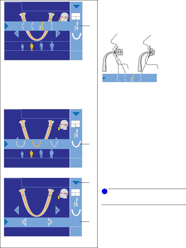
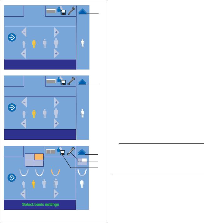
Program settings
When you touch a symbol in the “submenu” in
column (8), a submenu line for program settings opens.
8
L
10 |
|
There are 4 submenu lines for program settings |
|
available: |
|
|
|
|
|
|
1. Selection of half-views and individual quadrants |
|
64kV |
In this submenu, you can select a half-view of the jaw, |
|
i.e. right or left side (P1, P2, P10) or upper or lower jaw |
|
|
8mA |
|
|
(P1, P2, P10, P12) for programs P1, P2 and P10 includ- |
|
|
|
|
ORTHOPHOS is ready for exposure |
? |
ing constant magnification and artifact-free display. |
|
||
|
|
The preselected type of exposure is also displayed in the |
|
|
submenu column (8). |
R |
8 |
L |
10
|
64kV |
|
8mA |
ORTHOPHOS is ready |
? |
|
Selection of individual quadrants |
|
The full version of XG Plus offers the option of selecting |
|
individual quadrants. |
R |
8 |
L |
10
|
|
For each selection, please make sure that you know |
|
|
where to touch the icon (see finger). |
|
64kV |
You can reactivate the full screen mode by touching the |
|
center of the quadrant field. |
|
|
8mA |
|
|
|
|
ORTHOPHOS is ready for exposure |
? |
|
CEPH |
|
|
L |
|
8 |
|
|
|
64kV |
|
8mA |
ORTHOPHOS is ready for exposure |
? |
20 |
59 87 594 D 3352 |
D 3352.201.01.14.02 |
Sirona Dental Systems GmbH
Operating Instructions ORTHOPHOS XGPlus DS/Ceph
R |
L |
R |
L |
R |
L |
R |
L |
RightHalbseitehalfrechts-view |
|
|
LeftHalbseitehalf-linksview |
R |
L R |
L |
R |
L |
R |
L |
RightEinzelquadrindividualntquadrantrechts |
|
|
Left individualEinzelquadrantquadrantlinks |
3Controls and functional elements
3.2General touchscreen functions
Half-view and individual quadrant exposures
The adjacent illustrations show the X-ray image displays and indicate how the half-views and the individual quadrants are associated with the patient.
Individual quadrant exposures are possible only in the XG Plus full version.
The program duration for individual quadrant exposures equals the program duration for half-view exposures.
English
59 87 594 D 3352 |
21 |
D 3352.201.01.14.02 |
3 Controls and functional elements |
Sirona Dental Systems GmbH |
3.2 General touchscreen functions |
Operating Instructions ORTHOPHOS XGPlus DS/Ceph |
PAN |
CEPH |
TS |
|
|
1260 |
P1 |
|
|
|
|
SID = 19,6” |
|
8 |
|
|
6 x 12” |
|
|
|
|
|
|
64kV |
|
|
|
|
8mA |
|
ORTHOPHOS is ready for exposure |
? |
|
||
PAN |
CEPH |
TS |
|
|
1260 |
P1 |
|
|
|
10 |
14,1s |
|
|
|
|
|
|
|
|
|
SID |
|
|
8 |
|
|
|
64kV |
|
|
|
|
8mA |
|
ORTHOPHOS is ready for exposure |
? |
|
||
PAN |
CEPH |
TS |
|
9 |
1260 |
P1 |
|
|
|
10 |
14,1s |
|
|
|
|
|
|
|
|
|
62kV |
|
64kV |
8 |
|
8mA |
AEC |
8mA |
|
|
|
|||
ORTHOPHOS is ready for exposure |
? |
|
||
22 |
|
|
|
|
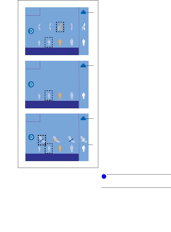
2. Presetting for malocclusions
Here you can preselect one level of retrusion as well as one or two levels of protrusion for programs P1, P2 and P10 including constant magnification and artifact-free display.
For preselection touch the corresponding tooth symbol in the submenu line.
64 |
SID = 19,6” |
10 |
6 x 12” |
3. Presetting for jaw shape
In this submenu you can preselect a normal jaw shape, a V-shaped jaw and a square jaw for programs P1, P2 and P10 including constant magnification and arti- fact-free display.
For preselection touch the corresponding tooth symbol in the submenu line.
4. Manual setting of kV/mA values
If the default kV/mA combinations do not provide satisfactory results, you can preselect intermediate kV/mA values in this submenu (for all programs) using the –/+ keys in the submenu line.
i NOTE
As long as the respective menu line is open, the background is displayed as inactive.
You can close a menu line:
–by touching the blue arrows in the menu line.
–by touching the corresponding symbol in the light blue area at the right margin.
59 87 594 D 3352 D 3352.201.01.14.02
Sirona Dental Systems GmbH |
3 Controls and functional elements |
Operating Instructions ORTHOPHOS XGPlus DS/Ceph |
3.2 General touchscreen functions |
PAN |
|
9 |
R |
L |
20 |
|
|
|
|
60kV |
|
|
|
60kV |
|
|
3mA |
3mA |
|||
|
|
|
|
|
|
|
|
|
|
|
|
|
? |
ProgrammeinstellungenSelect program settingswählen |
|
|||||
|
|
|
|
|
|
|
CEPH |
|
9 |
Quick |
Quick |
20 |
9,4s |
||
ON |
OFF |
|
60kV |
|
60kV |
9mA |
|
9mA |
?
TS |
|
9 |
R |
L |
20 |
|
|
|
2 |
71kV |
71kV |
12mA |
12mA |
?
Entire menu settings
Level 2
You may also display all of the program settings and make the settings described above in a second program level.
To access the second program level, touch the blue arrow (9) in the upper right corner of the touchscreen; the arrow will point upward then.
After having made your selections, you can return to program level 1 only by touching the blue arrow (9) once again.
i NOTE
When you confirm the exposure with the R key, the program settings changed in these submenu lines will automatically be reset to the default settings (except for Ceph Quickshot).
English
59 87 594 D 3352 |
23 |
D 3352.201.01.14.02 |
3 Controls and functional elements |
Sirona Dental Systems GmbH |
3.2 General touchscreen functions |
Operating Instructions ORTHOPHOS XGPlus DS/Ceph |
PAN |
|
9 |
|
|
|
||
Quick |
Quick |
Quick |
|
On |
Off |
||
|
|||
|
P1 |
P1 |
|
|
64kV |
64kV |
|
|
8mA |
8mA |
|
Select basic settings |
? |
||
CEPH |
|
9 |
|
|
|
||
|
C3 |
C3 |
|
|
73kV |
73kV |
|
|
15mA |
15mA |
|
Select basic settings |
? |
||
TS |
|
9 |
|
|
CEPH |
||
|
22 |
||
|
|
||
R |
L |
21 |
|
|
|
||
|
71kV |
71kV |
|
|
12mA |
12mA |
|
|
|
? |
|
24 |
|
|
|
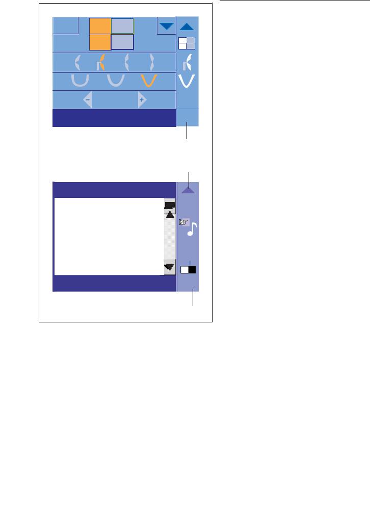
Basic Settings menu
Level 3
In a third program level, you can freely choose and then save certain exposure parameters for the individual programs.
To access the third program level, touch the arrow pointing downward (20) in the second program level.
The right arrow will then become a double arrow.
This menu can be closed again simply by touching the blue double arrow (9) in the upper right corner.
The display always returns to the standard menu (level 1).
 ATTENTION
If you want to change the kV/mA values in the TSA basic settings, make sure to first preselect the corresponding quadrant and jaw region.
The kV/mA change always applies only to this preselection.
59 87 594 D 3352 D 3352.201.01.14.02
Sirona Dental Systems GmbH |
3 Controls and functional elements |
Operating Instructions ORTHOPHOS XGPlus DS/Ceph |
3.2 General touchscreen functions |
PAN |
9 |
Select Start Settings |
|
CEPH |
9 |
Select Start Settings |
|
TS |
9 |
|
8 |
Select Start Settings |
|
59 87 594 D 3352 |
|
D 3352.201.01.14.02 |
|
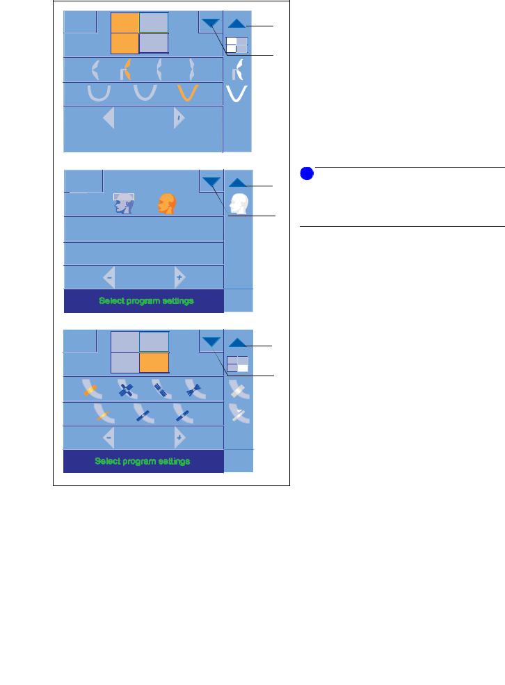
Start settings menu
Level 4
Various factory preset start parameters can be reprogrammed in level 4.
They are then displayed after each unit power-on and for each new exposure.
You can reach the 4th level by touching the disk icon (21) in the basic settings menu (level 3).
For PAN exposures you can change the abnormality preference (2nd icon from the right, as per factory setting) and the patient icon preference (2nd icon from the left, as per factory setting).
For CEPH exposures you can only change the patient icon preference (2nd icon from the left, as per factory setting).
For TS exposures you can change the slice thickness preference (left icon for the thinnest slice, as per factory setting) and the patient icon preference (2nd icon from the left, as per factory setting).
To perform a particular change, touch the desired icon; the icon then turns orange and is also displayed in column 8.
Then save the new presetting by touching the programming key symbols.
This menu can be closed again simply by touching the blue double arrow (9) in the upper right corner.
The display always returns to the standard menu (level 1).
i NOTE
The icons framed with a broken line represent the factory settings.
25
English
3 Controls and functional elements |
Sirona Dental Systems GmbH |
3.2 General touchscreen functions |
Operating Instructions ORTHOPHOS XGPlus DS/Ceph |
|
9 |
T |
R |
|
9 |
64kV
8mA
sure ?
19
8
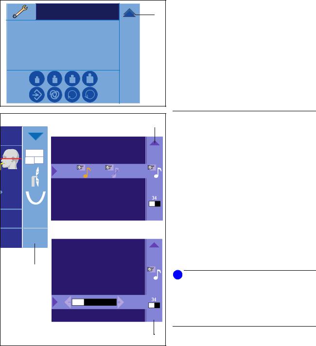
Service menu
The service menu is intended exclusively for service engineers.
The service engineer accesses the service menu by touching the wrench symbol (22) in the third program level.
Touchscreen settings
When you touch the question mark (19) in the lower right corner of the touchscreen, the help screen is displayed starting at the first level.
You can open two fly-out menus here by touching the corresponding symbols in column (8).
In the upper fly-out menu you can switch off the clicking tone of the touchscreen by activating the crossed-out musical note symbol.
In the lower fly-out menu, you can adjust the intensity of the touchscreen display with the –/+ keys. During this adjustment a reference value appears above the symbol in column (8).
i NOTE
Switch the unit on for at least 10 minutes before adjusting the touchscreen intensity to ensure that the touchscreen has reached its full brightness.
An hour glass is displayed during the run-up time.
As long as the hour glass is running, it is not possible to enter a change of intensity.
To close a fly-out menu, touch the blue arrow at the left end of the corresponding line or the relevant symbol in column (8).
To return to the previous level, touch the blue arrow (9) at the top of column (8).
26 |
59 87 594 D 3352 |
D 3352.201.01.14.02 |
Sirona Dental Systems GmbH
Operating Instructions ORTHOPHOS XGPlus DS/Ceph
PAN |
|
R |
L |
60kV |
60kV |
3mA |
3mA |
ProgrammeinstellungenSelect program settingswählen ?
19
9
ORTHOPHOS XG configuration |
1/2 |
|
|
======================= |
|
|
|
Serialnumber |
: 000000012 |
|
|
Systemsoftware |
: V.02.21.01 |
|
|
Bootmode |
: Static |
|
|
Type |
: 43 |
|
|
Network Name |
: Geraet1 |
|
|
MAC address |
: 00101900242d |
|
|
IP address |
: 192. 168. 15. 125 |
|
70 |
Subnet mask |
: 255.255.255.0 |
|
|
|
|
|
|
8
59 87 594 D 3352
D 3352.201.01.14.02
3Controls and functional elements
3.2General touchscreen functions
Info screen
Starting at level 2, the info screen is displayed when you touch the question mark (19) in the lower right corner of the touchscreen “ORTHOPHOS XG configuration”.
System data which may be useful when contacting your service engineer are displayed here.
If this list is too long to be displayed all at once, a scroll bar for paging up or down appears on the right.
You can activate the “touchscreen click tone” and “touchscreen intensity setting” fly-out menus from the help screen in column (8) here as well.
To return to the previous level, touch the blue arrow (9) at the top of column (8).
27
English
4 Accessories |
Sirona Dental Systems GmbH |
4.1 Rests and supports for panoramic exposures |
Operating Instructions ORTHOPHOS XGPlus DS/Ceph |
4 Accessories
4.1 Rests and supports for panoramic exposures
|
|
|
|
|
|
|
C |
1 |
2 |
D |
|
|
|
|
|
|
|
|
|||
|
|
|
|
|
|
|
|
|
||
|
|
|
|
|
|
A |
|
|
E1* |
|
|
|
|
|
|
|
|
|
|
|
|
|
|
|
|
|
|
B* |
|
|
|
|
|
|
|
|
|
|
|
E* |
|
|
|
PAN |
CEPH |
|
|
|
|
|
|
|
|
|
1260 |
TS |
TS |
|
|
|
|
|
|||
|
|
|
|
|
|
|
||||
64 |
|
|
|
|
|
|
|
|
|
|
T |
|
|
|
|
|
|
|
|
|
|
R |
|
|
|
|
|
|
|
|
|
|
ORTHOPHOS ist |
|
|
|
|
64kV |
|
|
|
|
|
aufnahmebereit |
AEC 8mA |
N* |
|
|
|
|||||
|
|
|
? |
|
|
|
||||
|
|
|
|
|
|
|
|
|
||
F* |
|
|
|
|
|
|
|
|
P* |
|
|
|
|
|
|
|
|
|
|
||
|
|
|
|
|
|
|
|
|
|
|
G |
|
|
|
|
|
|
H* |
|
|
|
|
|
|
|
|
|
L* |
|
|
|
|
|
|
|
|
|
|
|
|
|
|
|
|
|
|
|
|
|
|
|
|
|
M* |
|
|
|
|
|
|
|
J* |
|
|
|
|
K* |
|
|
|
|
|
||||
28 |
|
|
|
|
|
|
|
|
|
|
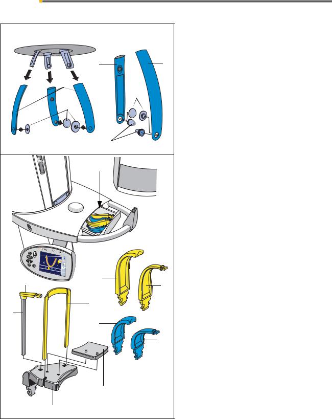
The accessories and the hygienic protective covers can be stored in the drawer between the two handles.
The forehead support and the temple supports (A) can be removed for cleaning after pressing the corresponding locking button.
Sterilization only in an autoclave at 135 °C, 2.1 bar.
All accessories marked with * can be sterilized.
For reorders:
AForehead support and temple supports
(can be removed for cleaning after pressing the corresponding locking button)
(1 pieces) Order No. 59 80 383
B* Contact pads for forehead/temple supports (1 pieces) Order No. 59 80 391
CTemporomandibular joint support “1” (right) for temporomandibular joint views Order No. 59 80 607
DTemporomandibular joint support “2” (left) for temporomandibular joint views Order No. 59 80 599
E* Ear holders for temporomandibular joint supports (10 pieces) Order No. 18 88 838
E1* Contact pads for temporomandibular joint supports (10 pieces) Order No. 59 90 648
F* Bite block
(10 pieces) Order No. 18 88 887
GBite block fixation
(5 pieces) Order No. 18 88 895
H* Bar for chin rest
Order No. 59 61 461
J* Chin pad
Order No. 14 49 227
K* Chin rest complete, incl. 5xF, 1xG, H, J, S, T Order No. 59 81 472
L* Contact segment blue for subnasale
for sinus/PNS and maxillary TSA views (5 pieces) Order No. 89 31 552
M* Bite block blue
for sinus and maxillary TSA views (5 pieces) Order No. 89 21 850
N* Contact segment standard yellow for subnasale
(5 pieces) Order No. 89 31 545
P* Bite block standard yellow
(5 pieces) Order No. 89 21 843
59 87 594 D 3352 D 3352.201.01.14.02
Sirona Dental Systems GmbH |
4 Accessories |
Operating Instructions ORTHOPHOS XGPlus DS/Ceph |
4.2 Important when inserting the temporomandibular joint supports |
4.2 Important when inserting the temporomandibular joint supports
1 |
2 |
|
“2“ |
||
|
||
“1“ |
|
2 |
1 |
“1“ |
|
|
|
“2“ |
|
|
R |
L |
|
|
|
|
|
|
“L“ |
“R“ |
|
|
59 87 594 D 3352 |
|
|
D 3352.201.01.14.02 |
|
|
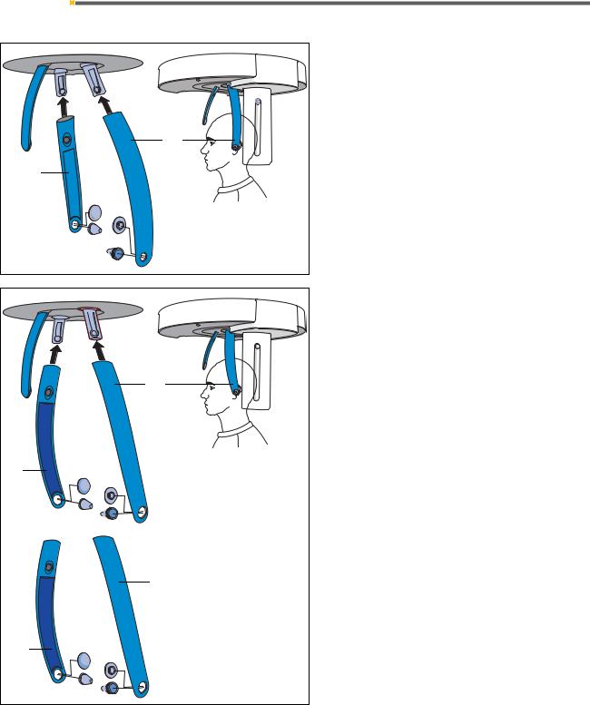
In ORTHOPHOS XG units delivered during/after 2006 the holders of the temple supports are tilted slightly toward the rear.
The temporomandibular joint supports are marked “1“ (for right) and “2“ (for left).
Insert the temporomandibular joint supports here as shown in the adjacent drawing.
All of the following drawings and descriptions contained in these operating instructions show this arrangement.
In ORTHOPHOS XG units delivered before
October 2006, the holders of the temple supports point straight down.
The temporomandibular joint supports marked “1“ and “2“ must be inserted here so that the support marked “2“ is positioned on the right and the one marked “1“ is positioned on the left.
For software updates of units delivered before
October 2006, the existing temporomandibular joint supports will be inserted in the familiar manner, i.e. marked “R“ for right and “L“ for left as shown.
For spare parts deliveries, your new temporomandibular joint supports will be marked “1“ for left and “2“ for right.
29
English
4 Accessories |
Sirona Dental Systems GmbH |
4.3 Protective covers for panoramic exposures |
Operating Instructions ORTHOPHOS XGPlus DS/Ceph |
4.3 Protective covers for panoramic exposures


 R
R
S
U
V
1
E1*
 E*
E*
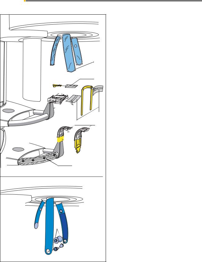
Prior to each exposure, the protective covers (disposable) must be fitted.
For the sake of clarity, the protective covers have been omitted on the subsequent illustrations.
For reorders of protective covers:
RFor forehead support and temple supports (500 pieces) Order No. 59 68 263 Dimensions: 150 mm x 47 mm
SFor bite block
(500 pieces) Order No. 33 14 072 Dimensions: 43 mm x 21 mm
TFor chin rest and bar
(100 pieces) Order No. 59 32 603 Dimensions: 75 mm x 60 mm
UFor bite blocks and contact segments (500 pieces) Order No. 33 14 080 Dimensions: 80 mm x 40 mm
VProtective foil for handles Order No. 59 68 255
E* Sterilizable ear holders for temporomandibular joint supports for temporomandibular joint views
(10 pieces) Order No. 18 88 838
E1* Sterilizable contact pads for temporomandibular joint supports for sinus views
(10 pieces) Order No. 59 90 648
30 |
59 87 594 D 3352 |
D 3352.201.01.14.02 |
Loading...