


 Loading...
$
7IVZMGI 1ERYEP
IMPORTANT:
•Please note that we have revised this version of the Service Manual.
It is therefore necessary that you no longer use the first edition.
•In case of faults which you are unable to eliminate with the help of this manual, please contact our Customer Service.
•It is essential that you take this Service Manual with you for every visit to a customer.
Furthermore, you must always have the spare parts list and the wiring diagrams with you as well.
You can order additional copies of this Service Manual under the
•order number 58 35 694 from our department GZP in Bensheim.
See reverse side of manual for address.
:IVWMSR
D 3344.076.01.04.02 03.2002
$ |
7IVZMGI 1ERYEP |
Additional requirements:
•Spare parts list
Order No. 58 62 581
•Circuit diagrams CEREC 3 / CEREC Scan
Acquisition unit: |
Order No. 58 35 710 |
Milling unit: |
Order No. 58 35 728 |
•Tools
–Hexagonal screwdriver (90° offset): Sizes 1.5; 2; 2.5; 4; 6
–Fork wrench, sizes 5.5; 8; 10; 14
–Torque screw driver, sizes 5, 6, 20, 25, 40
–Philips-head screw driver Size 1
–Slot screw driver, insulated, Size 2, 3
–Socket wrench 8mm
–Cutting pliers
–Special tool for monitor nut
–Special tool for locking button: Order No.: 59 08 947
•Accessories
–Digital multimeter, accuracy class: 1
–Soldering tool for repairing cables
–Side cutting pliers
–Cable ties
–Teflon tape
–PS2 mouse (recommended)
–PS2 keyboard (recommended)
–3.5” disk
–Calibration piece and pins (recommended)
–Fuses (recommended):
F1/F2 (2 pcs.) 5AT, Order No.: 20 33 111 F1/F2 (2 pcs) for acquisition unit starting with Ser. No.: 3300
|
6,3 AT, |
Order No.: 10 77 452 |
F3 |
1.25AL |
Order No.: 59 15 181 |
F4 |
2AT |
Order No.: 10 80 522 |

General 1
Service Software 2
Trouble Shooting: Milling Unit 3
Trouble shooting: Acquisition Unit 4
Settings 5
Acquisition Unit: Repairs 6
Milling Unit: Repairs 7
Installing Software 8

|
|
List of Contents |
|
|
|
|
|
1 |
General................................................................................................................................... |
1-1 |
|
|
1.1 |
General Notes .............................................................................................................. |
1-3 |
2 |
Service Software .................................................................................................................... |
2-1 |
|
|
2.1 |
General Notes .............................................................................................................. |
2-3 |
|
2.2 |
Basic Structure of Test Dialogs .................................................................................... |
2-5 |
|
2.3 |
Individual Test Points ................................................................................................. |
2-10 |
3 |
Trouble Shooting: Milling Unit................................................................................................. |
3-1 |
|
|
3.1 |
Device cannot be switched ON. Green LED (Ready for operation) not illuminated ... |
3-5 |
|
3.2 |
No connection to PC / acquisition unit. Software cannot be installed .......................... |
3-7 |
|
3.3 |
No air pressure............................................................................................................. |
3-9 |
|
3.4 |
Fan not running. Unit shuts down completely after a short time ................................ |
3-11 |
|
3.5 |
Water pump: Pressure too low ................................................................................... |
3-13 |
|
3.6 |
Defective light barrier ................................................................................................. |
3-15 |
|
3.7 |
Door switch. Please close milling chamber door........................................................ |
3-17 |
|
3.8 |
Motor locking positions: Problems changing grinders ................................................ |
3-19 |
|
3.9 |
Stepping motors (milling unit). Loss of steps.............................................................. |
3-21 |
|
3.10 |
Touch errors ............................................................................................................... |
3-23 |
|
3.11 |
Trouble shooting. Defective CCP board..................................................................... |
3-25 |
4 |
Trouble shooting: Acquisition Unit .......................................................................................... |
4-1 |
|
|
4.1 |
System cannot be switched ON ................................................................................... |
4-7 |
|
4.2 |
PC not booting properly I.............................................................................................. |
4-9 |
|
4.3 |
PC not booting properly II........................................................................................... |
4-11 |
|
4.4 |
PC does not respond during switch-on, PC power supply does not start .................. |
4-12 |
|
4.5 |
Further PC faults ........................................................................................................ |
4-14 |
|
4.6 |
Monitor image flickering ............................................................................................. |
4-15 |
|
4.7 |
No monitor display...................................................................................................... |
4-17 |
|
4.8 |
Incorrect monitor display format size.......................................................................... |
4-19 |
|
4.9 |
Monitor: Color shade/gray scale is too weak.............................................................. |
4-21 |
|
4.10 |
Trackball not functioning ............................................................................................ |
4-23 |
|
4.11 |
Trackball buttons not functioning................................................................................ |
4-25 |
|
4.12 |
Pedal not functioning.................................................................................................. |
4-27 |
|
4.13 |
Keyboard not functioning /defective ........................................................................... |
4-29 |
|
4.14 |
No camera image ....................................................................................................... |
4-31 |
|
4.15 |
Incorrect measuring sensor setting ............................................................................ |
4-33 |
|
4.16 |
Camera calibration: messages................................................................................... |
4-35 |
|
4.17 |
Interference at radio interface .................................................................................... |
4-37 |
|
4.18 |
No sound or sound level too low ................................................................................ |
4-41 |
|
4.19 |
No Sirocam camera image......................................................................................... |
4-43 |
|
4.20 |
Sirocam camera image interference .......................................................................... |
4-45 |
58 35 694 D 3344
D 3344.076.01.04.02 03.2002
V

List of Contents
|
4.21 |
SIROCAM camera: Incorrect image settings .............................................................. |
4-47 |
|
4.22 |
Digital X-ray problems ................................................................................................. |
4-49 |
5 |
Settings.................................................................................................................................... |
5-1 |
|
|
5.1 |
Monitor Settings ............................................................................................................ |
5-3 |
|
5.2 |
Calibrating the 3D camera ............................................................................................ |
5-4 |
|
5.3 |
Pairing the DECT-radio interface (EU) .......................................................................... |
5-5 |
|
5.4 |
Replacing a module of the DECT radio interface (EU) ................................................. |
5-8 |
|
5.5 |
Pairing the Futaba radio interface (USA/Japan) ........................................................... |
5-9 |
6 |
Acquisition Unit: Repairs ......................................................................................................... |
6-1 |
|
|
6.1 |
Electrical and Electromechanical Components ............................................................. |
6-4 |
|
6.2 |
Mechanical components ............................................................................................. |
6-30 |
7 |
Milling Unit: Repairs................................................................................................................. |
7-1 |
|
|
7.1 |
Milling Unit: General Activities....................................................................................... |
7-3 |
|
7.2 |
Replacing the Scanner.................................................................................................. |
7-5 |
|
7.3 |
Replacing the Drive and/or Motor ............................................................................... |
7-11 |
|
7.4 |
Checking / Adjusting Stop positions............................................................................ |
7-13 |
|
7.5 |
Stepping Motors: Replacing / Adjustment ................................................................... |
7-15 |
8 |
Installing Software ................................................................................................................... |
8-1 |
|
|
8.1 |
Acquisition Unit: Network Installation ............................................................................ |
8-3 |
|
8.2 |
How to install an MO drive .......................................................................................... |
8-25 |
VI
58 35 694 D 3344 D 3344.076.01.04.02 03.2002

1 General
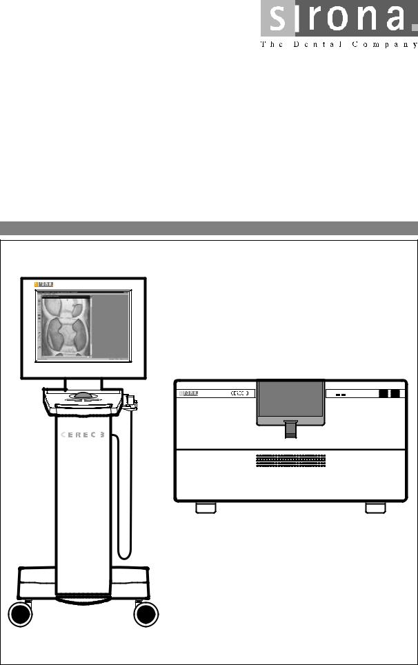
CEREC 3

List of Contents
General
List of Contents
1.1 General Notes ..................................................................................................................... |
1-3 |
1 - 2 |
58 35 694 D 3344 |
D 3344.076.01.04.02 03.2002 |
|
|
|
Nominal line voltage ranges
Faults in electronic medical equipment caused by mobile phones
Opening the device
Measurements
When replacing parts
Repairing and/or upgrading the PC drawer
Disposal
1.1 General Notes
1.1 General Notes
The CEREC® 3 acquisition unit can be used in the following nominal line voltage ranges:
• |
Europe |
230VAC / 50Hz |
• |
USA |
115VAC / 60Hz |
• |
Japan |
100VAC / 50Hz and 60Hz |
The CEREC 3 / CEREC Scan milling unit can be used in the following nominal line voltage ranges:
•100V – 230VAC; 50/60Hz
In order to ensure safe operation of electronic medical equipment, the use of mobile phones in practices and hospital areas is strictly prohibited.
When opening the device:
Please observe the necessary precautions when handling printed circuit boards (ESD).
Touch a ground point to discharge static electricity before handling any components.
Always switch OFF the device before connecting the measuring instrument.
Select the correct current/voltage type and adjust the measuring range to match the expected readings.
Perform continuity tests only on devices which are switched off.
Switch OFF the device before replacing any parts.
For safety reasons the device should be disconnected from the power supply when replacing parts around the line transformer.
The item numbers for ordering spare parts can be found in the spare parts list, Order No. 58 62 581.
The diagrams contained in the spare parts list provide a useful guide when replacing parts.
Replace the broken warranty seal on the bottom side of the PC drawer with the supplied seal of conformity.
Please observe the instructions found in the relevant user guide.
1.1
58 35 694 D 3344 |
1 - 3 |
D 3344.076.01.04.02 03.2002 |

2 Service Software
CEREC 3

List of Contents
Service Software
List of Contents
2.1 |
General Notes ..................................................................................................................... |
2-3 |
2.2 |
Basic Structure of Test Dialogs ........................................................................................... |
2-5 |
2.3 |
Individual Test Points .......................................................................................................... |
2-10 |
2 - 2 |
58 35 694 D 3344 |
D 3344.076.01.04.02 03.2002 |
|
|
|

2.1 General Notes
|
2.1 General Notes |
||
Test requirements |
Requirement for all tests: |
||
|
• PC / acquisition unit are switched on and ready for operation. |
||
|
• PC / acquisition unit and milling unit are interconnected (per interface ca- |
||
|
|
ble or radio link) |
|
|
• The software has been loaded for the milling unit (see Operating Instruc- |
||
|
|
tions for Milling Unit/Milling Unit Scan, Switching the units on, Initial |
|
|
|
start-up). |
|
|
• The door of the milling chamber must remain closed as long as any mo- |
||
|
|
tors or the water pump are running. |
|
|
|
If the door of the milling chamber is opened during the test, all motors and |
|
|
|
the water pump will switch off immediately (same function as pressing the |
|
|
|
Stop button). |
|
|
• The tools (burs) must be installed already during operation of the water |
||
|
|
pump. |
|
|
• During operation of the water pump, the air pump must always be running |
||
|
|
to protect the gearing against water damage, i.e. the air pump is started |
|
|
|
first. If the air pressure switch detects no air pressure, an error message |
|
|
|
will appear and the test can not be performed. |
|
Service Software Log File |
The service software is a component of the product software. This software |
||
|
generates a log file for all tests performed. |
||
|
This log file is located on delivery in the directory |
||
|
c:\programme\Cerec\System\Service\Protocols and is named |
||
|
Test file_XXXXXXXXXXXX.TXT |
||
|
The Xs here denote the serial no. of the controller board. |
||
|
Each time the service software is started, a confirmation query appears ask- |
||
|
ing whether this file (if it already exists) should be deleted. If NO (do not |
||
|
delete) is selected, the tests subsequently performed will be appended to the |
||
|
ones previously saved. Each test is labeled with a starting and ending date. |
||
|
The test file can be viewed with the editor at any time. If the user exits from a |
||
|
test without saving it, he will be asked if he really wants to quit without saving. |
||
|
If Yes (Quit without saving) is then selected, the data just measured will be |
||
|
lost. |
|
|
|
After completing a test section, the log file must be saved under a new name |
||
|
to a diskette belonging to the corresponding unit. |
||
Assessment scores |
There are three different scores which can be assigned to test results: |
||
|
• Passed fully (green label) |
||
|
• |
Passed (yellow label) |
|
|
• Not passed (red label) |
||
|
|
|
|
|
i |
NOTE |
|
|
These assessment categories apply starting with software version V1.1 |
||
|
R600 |
||
|
|
||
|
The score Passed (yellow label) may be irrelevant for a specific test. In this |
||
|
case n.a. (not applicable) will be written to the log file for this score. |
||
|
|
|
|
58 35 694 D 3344 |
|
2 - 3 |
|
D 3344.076.01.04.02 03.2002 |
|
||
|
|
|
|
2.1

2.1 General Notes
CAUTION
To ensure trouble-free operation of the system, all test results should be labeled "Passed fully".
If the test results are marked "Passed", uncritical changes have occurred at this point of time.
If the test results are labeled "Not passed", you must find and correct the fault(s)
Example of test protocol: Path: c:\programme\Cerec\System\Service\Protocols
i NOTE
If the milling unit housing is left open, the temperature switch on the CC PC board may cut out after a short time (T>90°C). The cooling fan can work properly only with the cover closed.
Overview of gearing unit:
Gearing 3
Gearing 1
Gearing 2 (without function)
2 - 4 |
58 35 694 D 3344 |
D 3344.076.01.04.02 03.2002 |
|
|
|

2.2 Basic Structure of Test Dialogs
2.2 Basic Structure of Test Dialogs
i NOTE
For a functional description of the menu items, see the user’s manual.
Via the Service menu you can ...
•select a wide range of Service functions with Settings/Service...
|
|
|
|
|
|
|
CAUTION |
|
|
|
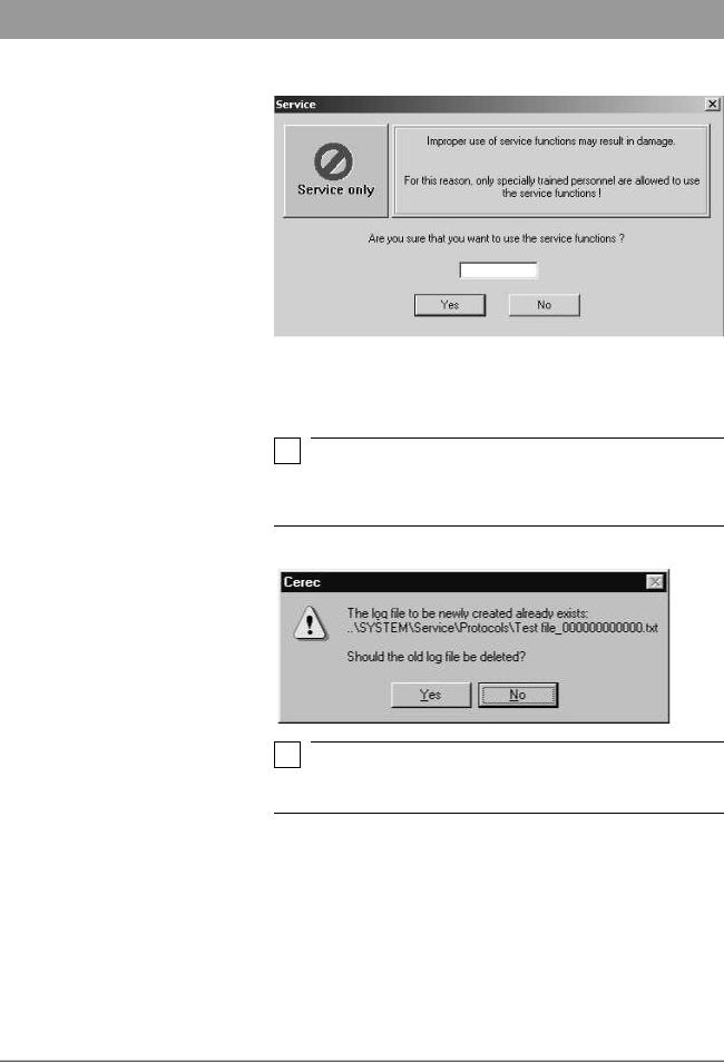
The Service functions may be used only by authorized service technicians |
|||
|
who have been trained by Sirona. |
|||
Password protection |
|
|
|
|
The service software test dialogs are protected by a password to prevent |
||||
|
manipulations by unauthorized users. |
|||
|
The password has four digits. It changes daily and is generated from the sys- |
|||
|
tem date of the computer according to the following scheme: |
|||
|
|
|
||
|
Password |
Generated from |
||
|
number |
|||
|
|
|||
|
1 |
|
|
2. number of the current month |
|
|
|
|
|
|
2 |
|
|
1. number of the current month |
|
|
|
|
|
|
3 |
|
|
2. number of the current day |
|
|
|
|
|
|
4 |
|
|
1. number of the current day |
|
|
|
||
|
Example: 24.05.2001 becomes 5042 |
|||
|
|
|
|
|
|
i |
NOTE |
|
|
|
Since the password is thus valid for only one day, it may be passed on to the |
|||
user in exceptional cases, e.g. when providing him with emergency help over the phone.
CAUTION
The password should always be treated confidentially. Before entering the password, always determine the date as inconspicuously as possible.
i NOTE
If you enter the correct password, and the commands are nevertheless not enabled, first check the system date of the computer.
The dialog for setting the system time can be called up in all Windows operating systems by double-clicking the time displayed in the status line.
2.2
58 35 694 D 3344 |
2 - 5 |
D 3344.076.01.04.02 03.2002 |
2.2 Basic Structure of Test Dialogs
Now enter the password.
If you confirm this Service dialog with Yes, the Test selection dialog box will open.
Log file
i NOTE
If a log file named after the milling unit already exists at the time of the program start, a confirmation query will appear asking if the data from the new test run should be appended to the existing file or it should be deleted first.
i NOTE
If the display "…0000.txt" appears, this means that there is no connection to the milling unit.
Possible causes:
•The CEREC 3 program has been started more than once
•There is no (cable or radio-link) connection between the milling unit and the acquisition unit/PC
•The software download to the milling unit has not been completed.
2 - 6 |
58 35 694 D 3344 |
D 3344.076.01.04.02 03.2002 |
|
|
|
2.2 Basic Structure of Test Dialogs
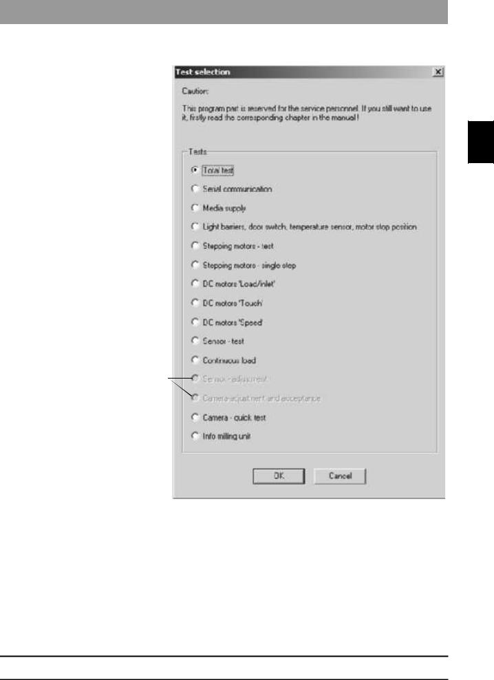
Test selection dialog
2.2
Tests performed only at the factory
In the Test selection dialog you can select …
•a Total test (default selection on delivery) or
•an individual test.
The selected test dialog is then opened by clicking on OK.
58 35 694 D 3344 |
2 - 7 |
D 3344.076.01.04.02 03.2002 |
2.2 Basic Structure of Test Dialogs
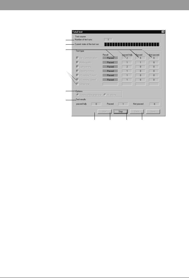
Example: Total test
1
2
10
3 
4
5
6 |
7 |
9 |
8 |
1.Number of test runs completed since the last time the Start button was actuated.
2.Status bar for current state of test run.
3.Check boxes for selecting (activating/deactivating) the tests available in this test dialog.
4.Check box for selecting the options possible in this test dialog.
5.Number of test results since the last Start:
–Passed fully
–Passed
–Not passed
6.Pressing Start initiates the test run with the selecting settings.
The test run will be repeated until it is interrupted with the Stop button. The test run counter is then reset to 0.
Once started, the test run can be halted only with Stop. No other inputs are possible during the test run.
7.The test is canceled as soon as possible with Stop.
The test in progress at the time of cancellation is not counted. All inputs are now possible again.
8.Save stores all existing data to the log file. The data are appended to the previously existing log file (if the current test run has not yet been saved). If no data exist, a message to that effect will appear (confirm with OK).
Once a test run has been saved to the log file, a new test run must be started before selecting the save function again.
2 - 8 |
58 35 694 D 3344 |
D 3344.076.01.04.02 03.2002 |
|
|
|
2.2Basic Structure of Test Dialogs
9.Press Back to quit the test dialog and return to the service dialog.
If any data exist and have not yet been saved, you will be queried whether or not the test data should be saved.
2.2
10. Result: |
|
|
• No color |
=> No measurement available yet |
|
• Green |
=> |
Measurement shows that test was Passed |
|
|
fully |
• Yellow |
=> |
Measurement shows that test was Passed |
• Red |
=> |
Measurement shows that test was Not |
|
|
passed |
58 35 694 D 3344 |
2 - 9 |
D 3344.076.01.04.02 03.2002 |
2.3 Individual Test Points
2.3 Individual Test Points
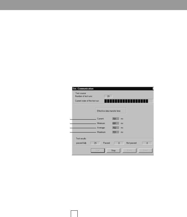
2.3.1 Serial Communication
The test is primarily used to measure the speed and quality of data transmission. This is especially important if the system is not operated through the standard line (RS-232 max. 10 m), but via other types of connections instead e.g. an infrared link, a DECT coupling or over longer distances via interface converters e.g. RS-422.
The transmission time between the beginning of transmission and the end of reception is calculated for a specific data record on the PC. A test run comprises one complete transmission in both directions.
The values thus measured are then saved to the log file.
Result of last test run
Minimum measured transmission time
Average measured transmission time
Maximum measured transmission time
Typical values:
|
|
|
COM1 |
COM1 |
|
|
|
|
Baud rate: 115200 |
Baud rate: 19200 |
|
|
|
|
|
|
|
Cable |
400-500ms |
– |
|||
|
|
|
|
|
|
Radio |
Europe |
600-750ms |
– |
||
|
|
|
|||
USA/Japan |
– |
2-3s |
|||
|
|
||||
|
|
|
|
|
|
|
|
|
|
|
|
|
|
|
|
|
|
|
i |
NOTE |
|
The limiting values and color coding refer to a |
|
|
baud rate of 115200. |
|
|
|
|
|
2.3.2 Media supply |
|
Purpose of Test: |
To check the media supply (air, water, fan) for proper functioning and test the |
|
|
pressure switches and the run-up time of the pump. |
|
|
|
|
2 - 10 |
|
58 35 694 D 3344 |
|
D 3344.076.01.04.02 03.2002 |
|
|
|
|

|
2.3 Individual Test Points |
|
|
Procedure |
The pumps and the fan are switched on by nominal select control depending |
|
on selection. The motor currents and the condition of the pressure switches |
|
are registered. The points of time when the pressure detectors respond are |
|
measured. After approx. 5 seconds the pumps are switched off and the time |
|
required until the pressure switch responds is measured and evaluated. |
Save |
Save stores the measured values to the log file under the heading of Media |
|
supply. |
2.3
|
i |
|
|
|
NOTE |
||
|
The limiting values apply to a completely filled water circuit. |
||
Deviations of measurements |
|
||
Deviations may occur: |
|||
|
• During the first test run (if any air is still in the water circuit) |
||
|
• If the amount of water in the water tank is insufficient |
||
|
• After filling the water tank. |
||
58 35 694 D 3344 |
2 - 11 |
D 3344.076.01.04.02 03.2002 |
2.3 Individual Test Points
|
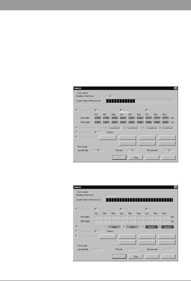
2.3.3 Light Barriers, Door Switch, Temperature |
|
Sensor and Motor Stop Positions |
Purpose of Test: |
This test serves to evaluate the safe functioning of the light barriers and check |
|
the door switch, the temperature sensor and the motor stop positions. |
Light Barriers |
When the end position is located, the slot of the gear is measured via the |
|
width and height at which the stepping motor positions are registered with the |
|
flanks. |
|
The light barriers to be tested can be selected in all variations. If no light bar- |
|
rier is selected, the Start button is not active. |
|
Default setting: All light barriers selected. |
Door Switch/Control Keys |
The current state of the door switch and control keys can be checked via a |
|
status bar display. |
2 - 12 |
58 35 694 D 3344 |
D 3344.076.01.04.02 03.2002 |
|
|
|

|
2.3 Individual Test Points |
|
|
Temperature |
A temperature display has been realized to check the temperature of the mill- |
|
ing machine. |
2.3
Motor Stop Positions |
In the Test selection dialog, Motor stop positions is defined as the default |
|
setting. |
|
The motors are moved to these positions to test the motor stop positions. |
|
Depending on which button is selected, the motors move to the correspond- |
|
ing position and stop there. |
|
The motors can be reset to their home positions by pressing the Home button. |
Stop position for tool change
Aux. position for replacing components
If the home position can not be reached or lost steps occur during motor movement, this will be reported.
58 35 694 D 3344 |
2 - 13 |
D 3344.076.01.04.02 03.2002 |

2.3 Individual Test Points
2.3.4 Stepping Motor Test
CAUTION
Observe the warnings in the Testpiece dialog.
Purpose of Test: |
This test serves to evaluate the functioning of the stepping motors. The step- |
|
ping motors are tested and evaluated for this purpose. The evaluation is made |
|
based on a factor for the reserve capacity of each stepping motor. In addition, |
|
this test can also be used for installation and adjustment purposes as well as |
|
to break in the milling machine. |
Procedure |
It is possible to individually trigger and test the stepping motors in various |
|
combinations. |
|
The stepping motors are run at various speed settings via an acceleration |
|
table and the resulting step losses are measured. The number of step loss |
|
events is then registered and evaluated. Finally, a reserve capacity is |
|
assigned to each motor based on this data. |
Display of Test Results |
In order to satisfy different requirements for adjustment and testing purposes, |
|
this test also offers the option of choosing between data summation and dis- |
|
play of the results for individual test runs. |
Rotation
Longit. movement
Standard
Refers to Stage 2
2 - 14 |
58 35 694 D 3344 |
D 3344.076.01.04.02 03.2002 |
|
|
|

2.3 Individual Test Points
2.3.5 Stepping Motors - Single Step
CAUTION
Observe the warnings in the opened dialog.
2.3
Purpose of Test: |
The test is used to control the motors individually in case of malfunction. |
Procedure |
Using the Move buttons, you can move the individual motors in the longitudi- |
|
nal and rotation directions. |
|
|
|
|
|
|
|
|
|
|
|
|
|
|
|
|
|
|
|
|
|
|
|
|
|
|
|
|
|
|
|
|
|
|
|
|
|
|
|
|
|
|
|
|
|
|
|
|
|
|
|
|
|
|
|
|
|
|
|
|
|
|
|
|
|
|
|
|
|
|
|
|
|
|
|
|
|
|
|
|
|
|
|
|
|
|
|
|
|
|
|
|
|
|
|
|
|
|
|
|
|
|
|
|
|
|
|
|
|
|
|
|
|
|
|
|
|
|
|
|
|
|
|
|
|
|
|
|
|
|
|
|
|
|
|
|
|
|
|
|
|
|
|
|
|
|
|
|
|
|
|
|
|
|
|
|
|
|
|
|
|
|
|
|
|
|
|
|
|
|
|
|
|
Grind |
Block |
Mill |
|
|
|
|
|
|
|
|
|
|
|
|
|
|
|
|
|
|
|
|
|
|
|
|
|
|
|
|
One longitudinal step (L) |
12.5µm |
12.5µm |
12.5µm |
|
|
|
|
|
|
|
|
|
|
|
|
equals |
|||
|
|
|
|
|
|
|
|
|
|
|
|
|
|
|
|
|
|
|
|
|
|
|
|
|
|
|
|
|
|
|
|
|
|
|
|
|
|
|
|
|
|
|
|
One rotational step (R) |
approx. 0.04° |
approx. 0.13° |
approx. 0.04° |
|
|
|
|
|
|
|
|
|
|
|
|
equals |
(2.5’) |
(7.7’) |
(2.5’) |
|
|
|
|
|
|
|
|
|
|
|
|
|
|
|
|
58 35 694 D 3344 |
2 - 15 |
D 3344.076.01.04.02 03.2002 |
2.3 Individual Test Points
|
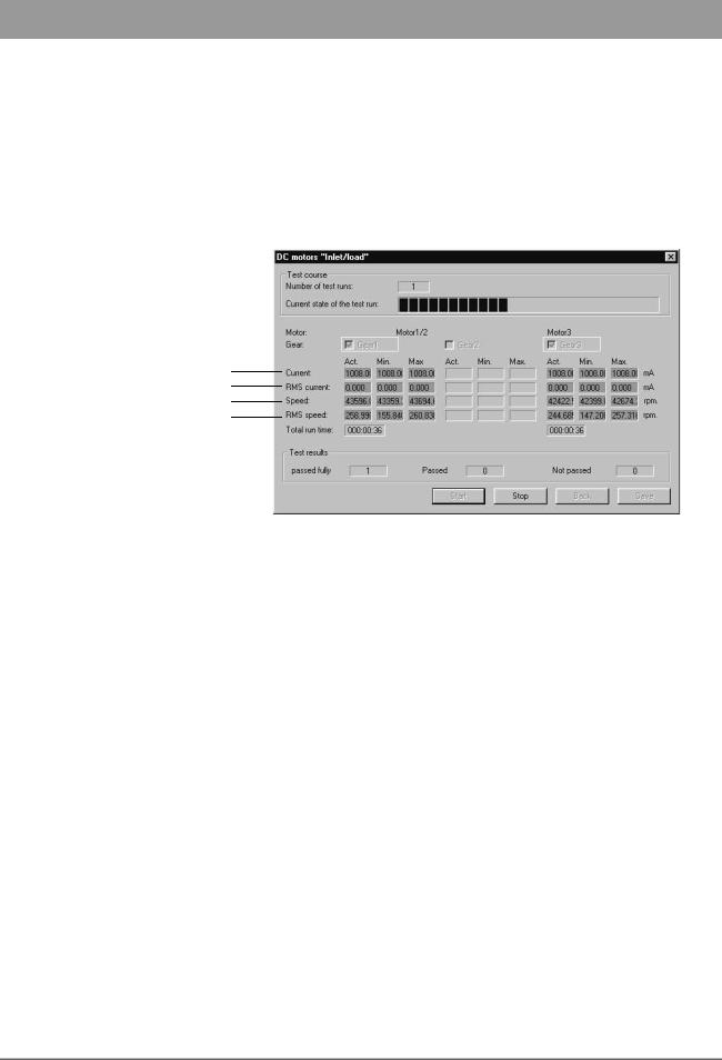
2.3.6 DC Motors "Inlet/Load" |
Purpose of Test: |
This test serves to run in the DC motors and check them for proper functioning |
|
under continuous load. |
Procedure |
The DC motors are tested through operation at a constant current. The result- |
|
ing speed provides an indication of the running resistance of the gearing units. |
Motor current
Always 0, since motor current preset
Actual speed
Measure of speed fluctuation
|
The two motors (Motor 1 and Motor 3) can be selected together or separately. |
|
If no motor is selected, the Start button is not active. Default: Both motors |
|
selected. |
|
Test Run: The test runs in an endless loop until the Stop button is actuated. |
|
The current measured values are displayed. A test run consists of one part |
|
run time and one part pause for each motor. |
|
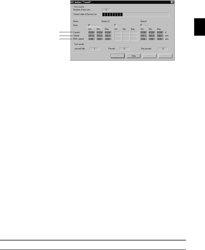
2.3.7 DC motors "Touch" |
Purpose of Test: |
This test is used to check the two DC motors for proper functioning in the Low- |
|
speed mode. |
2 - 16 |
58 35 694 D 3344 |
D 3344.076.01.04.02 03.2002 |
|
|
|
|
2.3 Individual Test Points |
|
|
Procedure |
The DC motors are tested by adjusting them to the touch speed (in the rele- |
|
vant directions of rotation). Then the relevant data are determined. |
Measured motor current
Measured speed
Fluctuation of speed
The possible gearing units (1,3) can be selected either together or separately.
The Start button remains inactive as long as no gearing has been selected.
Default: Both motors selected.
2.3
58 35 694 D 3344 |
2 - 17 |
D 3344.076.01.04.02 03.2002 |

2.3 Individual Test Points
|
2.3.8 DC motors ”Speed” |
Purpose of Test: |
This test is used to check the two DC motors and their gearings for flawless |
|
functioning in the High-speed mode. |
Measured speed Fluctuation of speed Measured motor current Fluctuation of motor current
Run-up time to 100% Run-up time to 70%
Maximum value of measured speed
Minimum value of measured speed
n  (r.p.m.)
Max. speed |
RMS speed |
|
100%
Min. speed
70%
|
|
|
t (s) |
|
Procedure |
The DC motors are tested by accelerating them from a standing start to work- |
|||
|
ing speed and then measuring the relevant data. |
|||
|
|
|
|
|
|
i |
NOTE |
|
|
|
The current is monitored during all measurements. The maximum current |
|||
|
must not stop for longer than 2 seconds; otherwise the test will immediately be |
|||
|
interrupted by an error message. |
|||
|
|
|
|
|
2 - 18 |
58 35 694 D 3344 |
D 3344.076.01.04.02 03.2002 |
|
|
|
Loading...