


 Loading...
kÉï=~ë=çÑW= MTKOMNR
loqelmelp=pi=Oa=L=loqelmelp=pi=Oa=`ÉéÜ=
loqelmelp=pi=Pa=L=loqelmelp=pi=Pa=`ÉéÜ
j~бенЙе~еЕЙ=fелнкмЕнбзел
bеЦдблЬ=ErpF

Sirona Dental Systems GmbH Maintenance Instructions ORTHOPHOS SL 2D / 3D
2 |
64 95 225 D3632 |
D3632.103.01.01.23 07.2015 |

Sirona Dental Systems GmbH |
Table of contents |
Maintenance Instructions ORTHOPHOS SL 2D / 3D |
|
Table of contents
1
2
3
4
5
6
7
8
9
10
11
Safety |
...................................................................................................................... |
|
4 |
Operation .......................................................................................................notes |
5 |
||
Auxiliary ........................................................................................devices required |
6 |
||
Visual ............................................................................................................check |
|
7 |
|
Optical ....................................................................................and acoustic signals |
8 |
||
5.1 ................................................... |
Checking the function of keys and buttons |
9 |
|
Checking ...................................................................the power supply connection |
11 |
||
Checking .......................................................................................the tube current |
13 |
||
Checking .......................................................................................the tube voltage |
17 |
||
Checking .....................................................................................the radiation time |
18 |
||
Checking ...........................................................................the laser light localizers |
19 |
||
Test exposures/Test ...................................................................................images |
22 |
||
11.1 .................................................................... |
Calling "Test exposures" menu |
23 |
|
11.2 ........................................................................................ |
2D test exposures |
24 |
|
............................................... |
11.2.1 Pan - diaphragm test exposure (2D) |
24 |
|
............................................ |
11.2.2 Pan - Symmetrical test exposure (2D) |
25 |
|
...................................................... |
11.2.3 Pan - quality test exposure (2D) |
26 |
|
...................................................................... |
11.2.4 |
Pan - test image (2D) |
28 |
.................................................... |
11.2.5 Pan - dark current exposure (2D) |
30 |
|
.................................................. |
11.2.6 |
Ceph - secondary diaphragm (2D) |
32 |
.................................................... |
11.2.7 Ceph - quality test exposure (2D) |
33 |
|
.................................................................... |
11.2.8 |
Ceph - test image (2D) |
36 |
11.3 ........................................................................................ |
3D test exposures |
38 |
|
............................................. |
11.3.1 Diaphragm test exposure (open) (3D) |
38 |
|
..................................... |
11.3.2 Diaphragm test exposure (collimated) (3D) |
40 |
|
....................................... |
11.3.3 Diaphragm test exposure (standard) (3D) |
42 |
|
............................................................... |
11.3.4 Quality test exposure (3D) |
44 |
|
............................................................................... |
11.3.5 |
Test image (3D) |
46 |
................................................................................ |
11.3.6 |
Dosimetry (3D) |
48 |
............................................... |
11.3.7 Quality control 21CFR 1020.33 (3D) |
49 |
|
Yearly ..................................................................................maintenance checklist |
#? |
||
64 95 225 D3632 |
3 |
D3632.103.01.01.23 07.2015 |

1 Safety |
Sirona Dental Systems GmbH |
|
Maintenance Instructions ORTHOPHOS SL 2D / 3D |
1 Safety
NOTICE
Qualifications of service personnel
Installationandstartupmaybecarriedoutonlybypersonnelspecifically authorized by Sirona.
 WARNING
Perilous shock hazard!
You must switch off the unit and then wait at least 1 minute, for measurements at the tube assembly at least 4 minutes, before you start to connect test cables or remove a cover!
For measurements in the area of the power supply terminal, the unit must be disconnected from the junction box of the building installation before you start to connect test cables!
 DANGER
X-rays
When performing the following tests, be sure to observe the radiation protection regulations applicable in your country (see Operating Instructions).
 DANGER
X-rays
"Radiation" is signaled by the message "X-RAY active!", a beep, and an X-ray LED.
NOTICE
Risk of damage to boards
Please observe the usual precautionary measures for handling printed circuit boards(ESD).Touch agroundpoint todischarge staticelectricity before touching any boards.
IMPORTANT
It is essential that you also observe the notes about the operation of the unit in the Operating Instructions.
4 |
64 95 225 D3632 |
D3632.103.01.01.23 07.2015 |

Sirona Dental Systems GmbH |
2 Operation notes |
Maintenance Instructions ORTHOPHOS SL 2D / 3D |
|
|
2 Operation notes |
|
Nominal line voltage |
|
The unit operates in the following nominal line voltage ranges: |
|
|
● 200 – 240 V |
|
|
● 50/60Hz |
|
|
The permissible line voltage fluctuation is ±10%. |
|
|
The internal line impedance must not exceed 0.8 Ω. |
|
|
Only permanent electrical connection of the unit is allowed. |
|
|
|
|
|
IMPORTANT |
|
|
|
|
|
The regulation "Federal Performance Standard for Diagnostic X-ray |
|
|
Units, Code of Federal Regulations, Title 21 CFR, Subchapter J" |
|
|
requires a corresponding power supply connection. |
|
|
|
Cooling period |
|
Thecoolingperiodbetweentwoexposuresismaintainedbyanautomatic |
|
|
exposure blocking function according to the pulse/pause ratio (see |
|
|
OperatingInstructions).Thedecrementingwaitingtimecountisdisplayed |
|
|
on the control panel. |
Measurements |
|
Always switch the unit off before connecting a measuring instrument. |
|
|
For safety reasons, the power supply should be switched off at the |
|
|
junction box of the building installation when performing measurements |
|
|
in the vicinity of the power supply unit. |
|
|
Select the correct current/voltage type and adjust the measuring range to |
|
|
match the expected readings. |
|
|
Perform continuity tests only on units which are switched off. |
|
|
If several exposures with radiation must be taken to check a |
|
|
measurement, make sure that the prescribed cool-down intervals are |
|
|
observed. They are maintained by an automatic exposure blocking |
|
|
function (see Operating Instructions). |
|
|
The pulse/pause ratio is 1:20, i.e. a 20-second pause is maintained for |
|
|
each second of radiation cycle. The pulse/pause ratio is automatically |
|
|
maintained (automatic exposure blocking). |
|
|
It is essential that you observe the radiation protection regulations |
|
|
applicable in your country prior to radiation release. |
64 95 225 D3632 |
5 |
D3632.103.01.01.23 07.2015 |
3 Auxiliary devices required |
Sirona Dental Systems GmbH |
|
Maintenance Instructions ORTHOPHOS SL 2D / 3D |
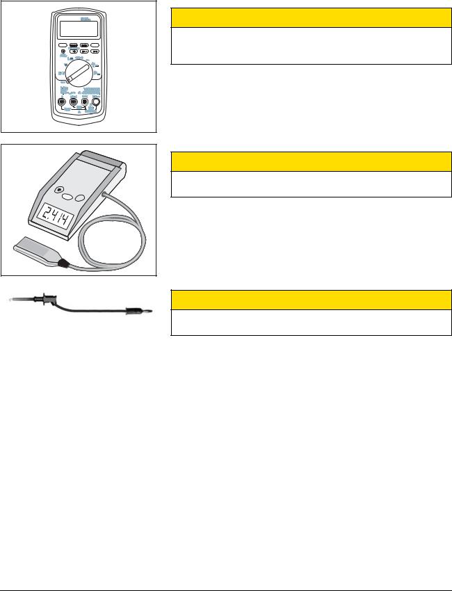
3 Auxiliary devices required
 CAUTION
Only use a battery-operated digital multimeter with safety sockets.
It is essential that you observe the safety and operating notes provided in the operating instructions of the multimeter.
● Battery-operated digital multimeter of type:
– Fluke 8000 A
– Philips PM 2816 rms
– or similar
 CAUTION
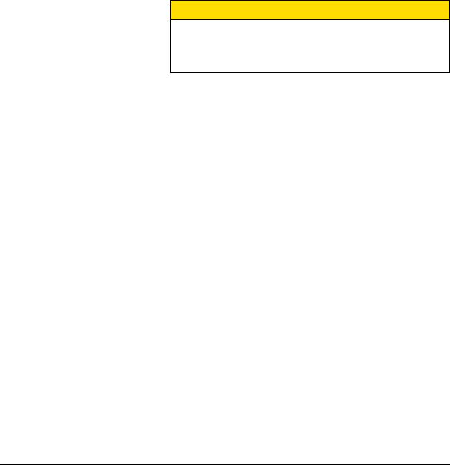
It is essential that you observe the safety and operating notes provided in the operating instructions of the dosimeter.
●Dosimeter for pulsed radiation of type:
–Mult-O-Meter 512L
– or similar
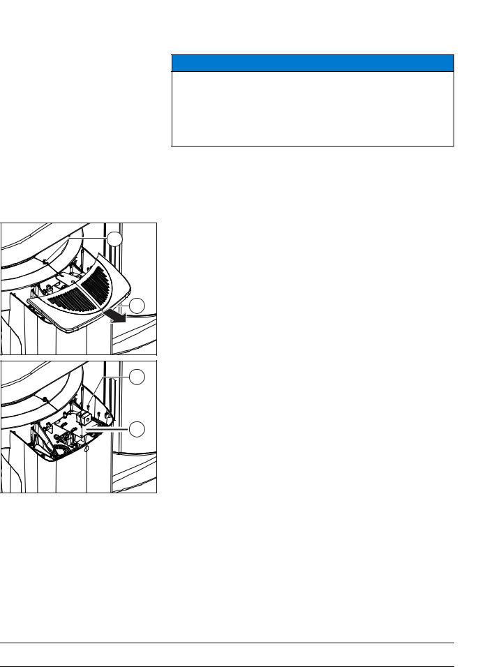
 CAUTION
Use exclusively fully insulated measuring wires.
Check the measuring wires for damages before use.
●Measuring wires with the following properties:
–dielectric strength > 1000V
6 |
64 95 225 D3632 |
D3632.103.01.01.23 07.2015 |

Sirona Dental Systems GmbH |
4 Visual check |
Maintenance Instructions ORTHOPHOS SL 2D / 3D |
|
4 Visual check
●Check for mechanical damage that could affect radiation protection.
●Check that all labels are attached and legible.
–Damaged/imperfect labels must be replaced.
You can order them in writing from Sirona (see back page for address),
stating the following:
–Customer's name
–Customer's address
●Check to see whether all model numbers and serial numbers must still be legible on the unit so that it can be identified.
64 95 225 D3632 |
7 |
D3632.103.01.01.23 07.2015 |

5 Optical and acoustic signals |
Sirona Dental Systems GmbH |
Maintenance Instructions ORTHOPHOS SL 2D / 3D
|
|
5 Optical and acoustic signals |
|
|
1. Turn the main switch (A) to position I. |
A |
B |
ª The X-Ray radiation indicator C lights up briefly. |
|
||
|
|
ª After approx. 2 seconds, the green LED B in the upper part of the |
|
|
control panel lights up. This LED remains lit as long as the unit is |
|
|
on. |
|
|
ª ThestartscreenappearsonthetouchscreenoftheEasypadand |
|
|
the initialization of the device starts running (for approx. 1 |
|
C |
minute). The rotating element rotates briefly clockwise and |
|
|
counterclockwise. The diaphragm moves into position. The |
|
|
forehead and temple supports on the panoramic unit open and |
|
|
close and then stop moving in fully opened position. |
2.Check the function of the keys.
ªPress a height-adjustment key. The movement of the heightadjustment motor is accompanied by an acoustic signal.
ªPress the keys for adjusting the forehead support and the temple
support. If the keys are working correctly, the supports stop automatically when they come into contact with the patient's head.
ªIf Remote has been installed, test the buttons and the display of the remote unit, too.
ªThe release button must not be defective or damaged.
See also the Operating Instructions, in the Operation section.
8 |
64 95 225 D3632 |
D3632.103.01.01.23 07.2015 |

Sirona Dental Systems GmbH |
5 Optical and acoustic signals |
Maintenance Instructions ORTHOPHOS SL 2D / 3D |
5.1 Checking the function of keys and buttons |
5.1Checking the function of keys and buttons
 WARNING
The unit emits X-ray radiation.
Excess exposure to X-rays is detrimental to health.
Use the prescribed accessories for radiation protection.
Do not stay in the X-ray room during exposure. Move as far away from the unit as the coiled cable for the release button allows you to.
|
|
"UnitON"LEDdisplayClightsup.PresstheRkeyDtomovetheunit |
||
A |
|
|
to the starting position. As long as no connection has been made to |
|
|
|
SIDEXIS,themessageisdisplayedinthecommentlineofthecontrol |
||
|
|
|
panel on the "Switch SIDEXIS to ready for exposure state" |
|
|
|
|
touchscreen. |
|
|
|
1. |
Switch on the PC. |
|
|
|
2. |
Start SIDEXIS (see SIDEXIS user manual). |
|
B |
|
C |
For further information and possible error messages, see Operating |
|
|
|
|
Instructions. |
|
|
|
3. |
Use the -/+ keys to select a program E. |
|
|
|
4. |
In the sub menu F, select a kV/mA combination with the -/+ keys. |
|
|
|
5. |
Check whether the patient symbols on the touchscreen can be |
|
|
|
|
selected in exactly the right position. |
|
|
|
|
If problems occur during selection, adjust the touchscreen). |
|
|
|
6. |
Press release button (A) and hold it down until the end of the |
|
|
Ready for exposure |
|
exposure. |
|
|
|
|
ª The exposure is released. "Exposure is performed" Appears in |
|
D |
E |
F |
the comment line on the touchscreen. |
|
Duringradiation,theopticalradiationindicator(B)lightsuponthe |
||||
|
|
|
||
|
|
|
Easypad; during radiation, an acoustic signal is also emitted. |
|
|
|
|
Radiation can be triggered multiple times during exposure. |
|
|
|
|
When the rotation and radiation switch off automatically, the |
|
|
|
|
exposure is complete. |
|
7.Let go of release button (A). ª The exposure is completed.
64 95 225 D3632 |
9 |
D3632.103.01.01.23 07.2015 |
5 Optical and acoustic signals |
Sirona Dental Systems GmbH |
5.1 Checking the function of keys and buttons |
Maintenance Instructions ORTHOPHOS SL 2D / 3D |
8.Cancel exposure - Check deadman function Select the same exposure parameters.
The operational readiness LED B flashes until the automatic coolingoff period of the X-ray tube assembly has expired (automatic exposure block).
9.Press the release button A.
10.Let go of the exposure release button.
ªThe exposure is immediately terminated.
The confirmation of the exposure data is displayed on the touchscreen. The radiation time and the area dose product (the lower two values) flash. In this way, an exposure that has been triggered can be canceled again at any time.
 CAUTION
Defective indicators and keys represent a risk to the safety of both the patient and the operator.
The user is not permitted to operate the unit until the necessary repairs have been made.
10 |
64 95 225 D3632 |
D3632.103.01.01.23 07.2015 |
Sirona Dental Systems GmbH |
6 Checking the power supply connection |
Maintenance Instructions ORTHOPHOS SL 2D / 3D |
|
6 Checking the power supply connection
To check the line voltage, the line voltage drop must be determined while creating an X-ray. To do this, proceed as follows:
Preparing the measurement
1.DANGER! After disconnecting the unit from the junction box of the buildinginstallation,waitatleast1minutebeforestartingtocheckthe line voltage!
Disconnect the unit from the junction box of the building installation.
2.Remove the "Bottom profile" cover (see Service Manual).


 K1
K1
300VAC
K1
3.CAUTION! Only use fully insulated measuring wires. Connect the measuring wires as shown in the illustration to the connectors L and N of the power supply terminal K1.
4.On the multimeter, select the voltage measuring range "300 VAC".
5.Re-attach the unit to the junction box of the building installation.
6.DANGER! Do not touch any live components!
Set the main switch (A) to I (see also Operating Instructions).
7.Wait for approx. 1 minute.
8.Press the R key.
ª The unit moves to its starting position.
Performing and analyzing a measurement
1.Set the highest kV/mA level, e.g. 90kV/12mA (see Operating Instructions).
2.Make ready for exposure in SIDEXIS.
3.CAUTION! Activating the release button triggers X-rays.
Activate the release button and take the voltage drop reading on the multimeter display.
ªIf the measured voltage drop does not fall within the permissible
tolerancerange(seethefollowingtable),notifythecustomerthat a suitable line voltage (according to the notes listed in the Installation Requirements) must be installed.
64 95 225 D3632 |
11 |
D3632.103.01.01.23 07.2015 |

6 Checking the power supply connection |
Sirona Dental Systems GmbH |
|
Maintenance Instructions ORTHOPHOS SL 2D / 3D |
IMPORTANT
In such a case, the unit must be switched off immediately and disconnected from the junction box of the building installation. It must not be placed in operation!
ªIf the measured voltage drop falls within the permissible
tolerance range (see the following table), finalize the measurement.
Permissible voltage drop:
Line voltage, with zero load |
Max. permissible |
|
line voltage drop |
180-208 V |
9 V |
|
|
208-230 V |
8 V |
|
|
230-240 V |
7.5 V |
|
|
240-264 V |
7 V |
|
|
Concluding the measurement
1.Switch the unit on via switch (A) (see also Operating Instructions).
2.Disconnect the unit from the junction box of the building installation.
3.DANGER!Waitatleast1minuteafterdisconnectingtheunitfromthe junction box of the building installation before removing the measuring wires!
Remove the measuring units from the unit.
4.Re-attach the "Bottom profile" cover to the unit.
12 |
64 95 225 D3632 |
D3632.103.01.01.23 07.2015 |
Sirona Dental Systems GmbH |
7 Checking the tube current |
Maintenance Instructions ORTHOPHOS SL 2D / 3D |
|
7
D |
E |
F |
G |
Checking the tube current
NOTICE
Damage to the measuring unit
The ring assembly and the tube assembly move during the measurement.
Make sure that the measuring wires are sufficiently long to allow for the ringmovementandthatthemeasuringunitisinasecurepositionsothat it will not fall down.
Preparing the measurement
1.Switch off the unit (see Operating Instructions).
DANGER! After switching off the unit, wait at least 4 minutes (LED V500 on the DX6 must no longer be on) before removing the cover on the tube assembly.
2.Loosen the screw (D) and remove the lid of the tube assembly cover
(E).
3. Loosen the 4 screws (F) and remove the cover plate (G).
64 95 225 D3632 |
13 |
D3632.103.01.01.23 07.2015 |

7 Checking the tube current |
Sirona Dental Systems GmbH |
|
Maintenance Instructions ORTHOPHOS SL 2D / 3D |
14 |
64 95 225 D3632 |
D3632.103.01.01.23 07.2015 |

Sirona Dental Systems GmbH |
7 Checking the tube current |
Maintenance Instructions ORTHOPHOS SL 2D / 3D |
|
4. |
DANGER! After switching off the unit, wait at least 4 minutes (LED |
|||
|
|
|
|
V500 on the DX6 must no longer be on) before removing jumper H |
|
|
|
|
from the DX6 board. |
|
|
|
|
Remove the jumper (H) from connector X302 on the DX6 board. |
5. |
DANGER! Only use fully insulated measuring wires. |
|||
|
|
|
|
Connect the digital multimeter with the measuring wires to test points |
|
|
|
|
MA- (X5-) and MA+ (X4+) at connector X302 on the DX6 board. |
6. |
On the multimeter, select the current measuring range 20mA DC. |
|||
|
7. |
NOTICE!Ifthelidofthetubeassemblycoverisnotattached,thering |
||
|
|
|
||
D |
|
circulation is impeded and the unit can be damaged. |
||
|
|
|
|
Temporarily install the lid of the tube assembly cover (E) on the unit |
|
|
|
|
using the screw (D). |
|
8. |
DANGER! Do not touch any live components! |
||
|
|
|
|
Set the main switch (A) to I (see also Operating Instructions). |
|
9. |
Wait for approx. 1 minute. |
||
|
|
E |
|
|
|
|
|
||
|
|
|
|
|
10.Touch the R key on the touchscreen.
ª The unit moves to its starting position.
Performing measurements
1.Select the P1 program (see Operating Instructions).
2.Set the highest kV/mA level, 66kV/8mA (see Operating Instructions).
3.Establish readiness for exposure (see SIDEXIS 4 Operator´s Manual).
4.CAUTION! Activating the release button triggers X-rays.
Start the exposure by pressing the release button. Hold down the release button until image acquisition is completed and the acoustic signal that indicates the end of the exposure can be heard.
IMPORTANT
1 mA corresponds to a tube current of 1 mA. The permissible tolerance is ± 20 %.
Analyzing measurements
Read the voltage value on the display of the multimeter.
ªThe tube current must be 8mA ± 1.6mA.
ªIf the measured value is not within the permissible tolerance, replace the tube assembly.
ªIf the measured value falls within the permissible tolerance, conclude the measurement.
64 95 225 D3632 |
15 |
D3632.103.01.01.23 07.2015 |

7 Checking the tube current |
Sirona Dental Systems GmbH |
|
Maintenance Instructions ORTHOPHOS SL 2D / 3D |
D |
E |
F |
G |
D |
E |
Concluding the measurement
1.Switch the unit on via switch (A) (see also Operating Instructions).
2.Loosen the screw (D) and remove the lid of the tube assembly cover
(E).
3.DANGER! After switching off the unit, wait at least 4 minutes before removing the measuring wires or reinserting the jumper!
Remove the measuring wires and bridge with the test points MA+/ MAon the DX6 board again with the jumper (H).
4.Reattach the cover plate (G) to the tube assembly with the 4 screws
(F).
5.Reattach the lid of the tube assembly cover (E) to the unit and secure it with the screw (D).
16 |
64 95 225 D3632 |
D3632.103.01.01.23 07.2015 |

Sirona Dental Systems GmbH |
8 Checking the tube voltage |
Maintenance Instructions ORTHOPHOS SL 2D / 3D |
|
8 Checking the tube voltage
Preparing the measurement
1. Attach the Mult-O-Meter sensor in the middle of the sensor (on 2D sensor side).
2. Set the main switch (A) to I (see also Operating Instructions).
3. Wait for approx. 1 minute.
A
4.Touch the R key on the touchscreen.
ª The unit moves to its starting position.
Performing measurements
1.Select the P1 program (see Operating Instructions).
2.Set the kV/mA level 63kV/8 mA (see Operating Instructions).
3.Establish readiness for exposure (see SIDEXIS 4 Operator´s Manual).
4.CAUTION! Activating the release button triggers X-rays.
Start the exposure by pressing the release button. Hold down the release button until image acquisition is completed and the acoustic signal that indicates the end of the exposure can be heard.
Analyzing measurements
Read the voltage values on the display of the Mult-O-Meter.
IMPORTANT
The measured tube voltage must correspond with the tube voltage set of 63kV. The permissible tolerance is ± 10 %.
ªIf the measured values are not within the permissible tolerance range, replace the tube assembly.
ªIf the measured values are within the permissible tolerance range, finalize the measurement.
Concluding the measurement
Switch the unit on via switch (A) (see also Operating Instructions).
64 95 225 D3632 |
17 |
D3632.103.01.01.23 07.2015 |
9 Checking the radiation time |
Sirona Dental Systems GmbH |
|
Maintenance Instructions ORTHOPHOS SL 2D / 3D |
9 Checking the radiation time
Preparing the measurement
1. Attach the Mult-O-Meter sensor in the middle of the combisensor (on
2D sensor side).
A2. Set the main switch (A) to I (see also Operating Instructions). 3. Wait for approx. 1 minute.
4. Press the R key.
ª The unit moves to its starting position.
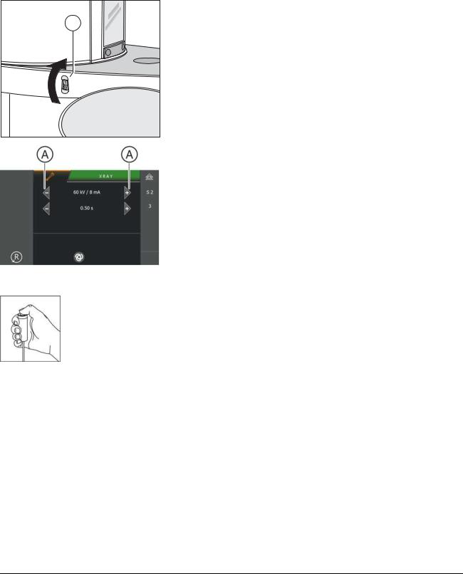
5.Call the Service menu and the Service routine S002.3 (see Service Manual).
6.Use the arrow keys (A) in selection field 1 to select the kV/mA level 60 kV/8 mA.
7.Use the arrow keys (A) in selection field 2 to select the radiation time 0.5 s.
Performing measurements
Initiate the radiation. Hold the release button pressed until the set radiation time has expired.
Analyzing measurements
Read the radiation time on the Mult-O-Meter.
ªThe value for the radiation time displayed on the Mult-O-Meter
must correspond to the radiation time of 0.5s selected in the service routine. The permissible tolerance is ± 10 %.
ªIf the measured radiation time doesnot fall within the permissible tolerance, replace the tube assembly (see Service Manual).
ªIf the measured radiation time falls within the permissible tolerance, finalize the measurement.
Concluding the measurement
1.Exit the service routine.
2.Switch the unit on via switch (A) (see also Operating Instructions).
18 |
64 95 225 D3632 |
D3632.103.01.01.23 07.2015 |

Sirona Dental Systems GmbH |
10 Checking the laser light localizers |
Maintenance Instructions ORTHOPHOS SL 2D / 3D |
|
10 Checking the laser light localizers
 CAUTION
Risk of injury to eyes.
The unit contains lasers of Class 1.
Keep a distance of at least 4" (10 cm) between eye and laser. Do not look into the laser beam.
Checking the laser light localizers
Preparing the test
1. Insert the forehead and temple supports.
2. Set the main switch (A) to I (see also Operating Instructions). 3. Wait for approx. 1 minute.
4.Touch the R key on the touchscreen.
ª The unit moves to its starting position.
64 95 225 D3632 |
19 |
D3632.103.01.01.23 07.2015 |
Loading...