


a^`=PROFESSIONAL
pЙкобЕЙ=j~ем~д |
= |
|
|
|
|
|
bеЦдблЬ |
|
|
|
|
|
|
|
Sirona Dental Systems GmbH
Operating Instructions DAC Professional
2 |
59 57 928 D 3370 |
D 3370.201.01.11.02 |
Content |
Page |
Installation of the Dac Professional…………………………………………… |
2 |
Maintenance…………………………………………………………………... |
9 |
Fault 1: Vacuum system………………………………………………………. |
15 |
Fault 2: Steam generator……………………………………………………… |
20 |
Fault 4: Pressure Release……………………………………………………… |
21 |
Fault 6: Ventilation……………………………………………………………. |
22 |
Fault 8: Time base…………………………………………………………... |
23 |
Fault 9: Door open…………………………………………………………….. |
24 |
Fault 10: Overheating of the Steam generator………………………………… |
25 |
Fault 12: Door locking………………………………………………………... |
27 |
Fault 14: No feed water……………………………………………………….. |
28 |
Fault 18: Sensor “nr” Input “ nr”……………………………………………... |
32 |
Fault 21: Preheating…………………………………………………………… |
34 |
Fault 22: Overheating of preheating…………………………………………... |
35 |
Fault 26: A/D-converter………………………………………………………. |
36 |
Fault 27: Temp.Sens.def 1,2…………………………………………………... |
37 |
Fault 29: Battery RAM………………………………………………………... |
38 |
Fault 31: System leak…………………………………………………………. |
39 |
Fault 32: Power loss / Sterilize sterile filter…………………………………... |
41 |
Fault 33: Pressure loss………………………………………………………… |
42 |
Fault 34: Sterilization TU……………………………………………………... |
43 |
Fault 35: Sterilization TO……………………………………………………... |
46 |
Fault 36: Sterilization PU……………………………………………………... |
48 |
Fault 37: Sterilization PO……………………………………………………... |
49 |
Fault 38: Sterilisation TD……………………………………………………... |
50 |
Fault 48: Parameters…………………………………………………………... |
51 |
Possible solutions for drying problems……………………………………….. |
52 |
Cycle printout…………………………………………………………………. |
53 |
Cycle process………………………………………………………………….. |
54 |
Saturated steam table………………………………………………………….. |
55 |
Helix test………………………………………………………………………. |
56 |
Bowie & Dick test…………………………………………………………….. |
57 |
Valve diagram………………………………………………………………… |
58 |
Diagnosis program……………………………………………………………. |
59 |
Service program………………………………………………………………. |
60 |
Revision history……………………………………………………………….. |
61 |

Installation of the DAC Professional
Figure 1 General features
1 |
Water storage tank |
11 Power cable |
|
|||
2 |
Emergency overflow (OUT) |
12 Front adjustable feet of the unit |
|
|||
3 |
One-way drain (OUT) |
13 Serial data and printer interface (RS 232). |
||||
|
|
|
|
In combination with NitraWin use serial modem cable |
||
4 |
Spring-operated safety valve – |
14 Fuses for the unit: 2 × 16 A / FF |
||||
|
release betw. 2.9 – 3 bar |
|
|
|
|
|
5 |
Connection for demineralised / |
15 Power switch |
|
|||
|
distilled water (OUT) |
|
|
|
|
|
6 |
Sterile filter |
|
16 Sliding-lock handle |
|
||
7 |
Connection for pressure release |
17 Hinged door (opens to the left) |
|
|||
|
for water storage tank (IN) |
|
|
|
|
|
8 |
Cooler/Blower |
|
18 Operator’s control and monitoring panel |
|||
9 |
Connection for demineralised / |
19 Cover to water tank |
|
|||
|
distilled water (IN) (quick-fitted |
20 Drain hose for water tank, drain side (OUT) |
||||
|
threaded connection for 6 x 1 |
|
|
|
|
|
|
hose) |
|
21 Drain hose for water tank, demineralised-water side (OUT) |
|||
10 Connection for 8 x 1 pressure |
||||||
|
release (OUT) |
|
|
|
|
|
|
|
55 |
|
19 |
|
|
|
|
|
18 |
|
|
|
|
|
|
|
1 |
|
|
|
|
|
|
17 |
|
|
|
|
|
|
2 |
Rear view |
|
|
|
|
|
|
||
|
|
|
|
16 |
3 |
|
|
|
|
|
4 |
|
|
|
|
|
|
|
|
|
|
|
|
|
|
5 |
|
|
|
|
|
|
6 |
|
|
|
|
|
|
7 |
|
|
|
|
|
|
8 |
|
|
|
|
|
|
9 |
|
|
|
|
|
15 |
10 |
|
|
|
|
|
14 |
|
|
|
|
|
|
13 |
11 |
|
|
|
|
|
12 |
|
|
|
20 |
21 |
|
|
|
|
|
|
|
175 |
150 |
250 |
|
Side view
370 |
|
|
70 |
|
|
|
|
|
|
460
09/21/2006 |
2/61 |
Servicemanual DAC Professional |

Required Space:
Before setting up the autoclave you should make sure that the following requirements are met: The DAC Professional is not designed to be installed in a cupboard or enclosed space. In order to ensure adequate ventilation, there should be at least 10 cm clearance to the sides (for dimensions see Figure1), and 10 cm clearance at the rear for connections.
Above the autoclave there must be sufficient space to allow access to the built-in water storage tank
(1) and for a good circulation of air.
The DAC Professional operates with a blower (8) on the rear of the unit, as part of the cooling system.
The functioning and the service life of the unit can be impaired if the blower (8) is not allowed to freely remove the heat from the unit.
Important: Before installing the unit, make sure that there is sufficient free circulation of air around the unit.
A plane, horizontal surface is required which is sufficiently stable to support the autoclave (unloaded weight 43 kg).
Make sure that the inside of the chamber is in level and then turn the front feet 3 times down (see figure 2).
Figure 2
The inside of the chamber should be in level and then the front feet are turned 3 turns down.
09/21/2006 |
3/61 |
Servicemanual DAC Professional |

Power supply
The power supply should be 230 V, 50 - 60 Hz, and 2500 W, with ground protection and a 16 A fuse.
The power cable supplied is 1.35 m long.
If the NITRAprint® is used, then an additional power socket will be required.
One-way-outlet
The wastewater outlet should be at least 30 cm lower than the autoclave and the connection pipe should not sag or be twisted, so that all water can drain away.
The supply with feed water (distilled or demineralised)
If an autoclave has a closed-loop water system, impurities in the water regularly lead to damage. Therefore, the DAC Professional has a one-way system.
The autoclave automatically withdraws the feed water it needs, from the internal water storage tank
(1) which has to be refilled with purified water.
The quality of the feed water (for steam generation) must be below 15µS to comply with EN13060.
Destilled or demineralised water below 15µS.
Waste-water tank
The DAC Professional is directly supplied with demineralised / distilled water through a hose from the built-in water storage tank (right side of the tank (front side)). The advantage of this system is that only electric power is required, and no water from the mains. A sensor measures the water level in the water storage tank. If the water level is too low, the system will warn the user that the tank must be filled before the program can start. The drain water (used feed water) is collected in the waste-water tank (left side of tank (front side)) and must be manually drained. When the wastewater tank becomes full, the system will warn the user that the tank must be drained before a program can start. This is the standard condition of the equipment as delivered. See figure 4.
Clean and empty the wasted water tank and the clean water tank every 2nd week (see operating manual)
09/21/2006 |
4/61 |
Servicemanual DAC Professional |
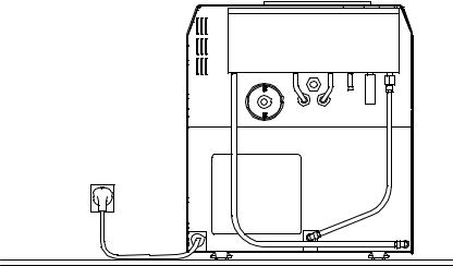
Figure 4
Back view
09/21/2006 |
5/61 |
Servicemanual DAC Professional |

One-way-outlet
Wastewater outflow is possible via a wall-mounted trap or a double-chamber trap under a sink. Example is shown on figure 5. A 1 meter outlet connection pipe can be supplied on request. The wastewater outlet should be at least 30 cm lower than the autoclave and the connection pipe should not sag or be twisted, so that all water can drain away.
Figure 5
Back view
3
30 |
29 |
|
31 |
||
|
09/21/2006 |
6/61 |
Servicemanual DAC Professional |

eуЦбЙеЙ
fелн~дд~нбзелйкзнзвздд=L= |
fелн~дд~нбзе=oЙйзкн=L=t~кк~ену= |
mкзнзЕздЙ=ЗЫбелн~дд~нбзе=L= |
mкзнзЕздз=ЗЙ=гзен~аЙ=L= |
|
||||||||||||||||||||||||||||||
|
||||||||||||||||||||||||||||||||||
d~к~енбЙй~лл |
m~ллйзкн |
СбЕЬЙ=ЗЙ=Ц~к~енбЙ |
|
|
m~л~йзкнЙ=ЗЙ=Ц~к~ен∞~ |
|
||||||||||||||||||||||||||||
|
|
|
|
|
|
|
|
|
|
|
|
|
|
|
|
|
|
|
|
|
|
|
|
|
|
|
|
|
|
|
|
|
||
Kunde / Customer / Client / Cliente |
Händler / Dealer / Depositaire / Depositante |
|
||||||||||||||||||||||||||||||||
Adresse, Tel.: |
|
|
|
|
|
|
|
|
|
|
|
|
|
Adresse, Tel.: |
|
|
|
|
|
|
|
|
|
|
|
|
|
|
|
|
|
|
||
Address, tel.: |
|
|
|
|
|
|
|
|
|
|
|
|
|
Address, tel.: |
|
|
|
|
|
|
|
|
|
|
|
|
|
|
|
|
|
|
||
Adresse, tel.: |
|
|
|
|
|
|
|
|
|
|
|
|
|
Adresse, tel.: |
|
|
|
|
|
|
|
|
|
|
|
|
|
|
|
|
|
|
||
Dirección, tel.: |
|
|
|
|
|
|
|
|
|
|
|
|
|
Dirección, tel.: |
|
|
|
|
|
|
|
|
|
|
|
|
|
|
|
|
|
|
||
|
|
|
|
|
|
|
|
|
|
|
|
|
|
|
|
|
|
|
|
|
|
|
|
|
|
|
|
|
|
|
|
|
|
|
Kundennummer / Customer No. |
|
|
|
|
|
|
|
|
|
|
|
|
|
Auftragsnummer / Order No. |
|
|
|
|
|
|
|
|
|
|
|
|
|
|
|
|
|
|
||
No. du client / No. de cliente |
|
|
|
|
|
|
|
|
|
|
|
|
|
No. de commande/No.de pedido |
|
|
|
|
|
|
|
|
|
|
|
|
|
|
|
|
|
|
|
|
|
|
|
|
|
|
|
|
|
|
|
|
|
|
|
|
|
|
|
|
|
|
|
|
|
|
|
|
|
|
|
|
|||
|
|
|
|
|
|
|
|
|
|
|
|
|
|
|
|
|
|
|
|
|
|
|
|
|
|
|
|
|
|
|
|
|
|
|
Seriennummern / Serial numbers / Numéros de série / Numéros de serie |
Pos. Serial-No. |
Modell |
|
|
|||
|
|
|
|
|
DAC Universal |
|
|
|
|
|
|
|
SIROCLAVE |
B |
|
|
|
|
|
||||
Rückseite |
|
|
|
|
VS |
|
|
rear |
|
|
|
|
|
||
verso |
|
|
|
|
|
|
|
dorso |
|
|
|
|
|
S |
|
|
|
|
|
|
|
||
|
|
|
|
|
SIROPRINT |
|
|
|
|
|
|
|
SIROSEAL |
|
|
|
|
|
|
|
SIROCLEAN |
|
|
|
|
|
|
|
|||
|
|
|
T |
|
|
|
|
|
Rückseite |
|
|
SIROMINI B |
|
|
|
|
rear |
|
|
|
|
|
|
|
verso |
|
|
|
|
|
|
|
dorso |
|
|
|
|
|
|
|
|
|
SIROMINI B |
|
|
|
|
Inbetriebnahme gemäß bauseitiger Installationsanleitung und Montageanleitung sowie bedarfsweise länderspezifische sicherheitstechnische Kontrollen fehlerfrei durchgeführt.
Commissioning performed error-free according to the pre-installation instructions and installation instructions, as well as country-specific safety controls where required.
Mise en service exécutée conformément aux instructions d’installation et aux instructions de préinstallation et éventuels contrôles de sécurité spécifiques au pays exécutés sans détection de défauts.
Puesta en funcionamiento según las instrucciones de instalación y de montaje en la obra así como, si es necesario, de haber efectuado controles técnicos de seguridad específicos del país exentos de defectos.
Äußerer Gerätezustand einwandfrei / Visual inspection of unit shows no defects / |
|
|
Etat extérieur correct de l’appareil / Estado externo de la unidad en perfectas condiciones |
||
|
||
Betreiber bzw. autorisierte Person unterwiesen / Operator or authorized person trained / |
|
|
Exploitant ou personne autorisée a été avisé(e) / Usuario y/o persona autorizada instruidos |
||
|
||
Name / Name / Nom / Apellido |
|
Kunde / Customer |
|
Unterwiesene Person / Trained person / |
Verkäufer / Sales rep. |
|
Techniker / Technician |
||
Client / Cliente |
|
Personne initiée / Persona instruida |
Vendeur / Vendedor |
|
Technicien / Tecnico |
||
|
|
|
|
|
|
||
|
|
|
|
|
|
||
Unterschrift / Signature / |
Signature / Firma |
|
|
|
|
||
|
|
|
|
|
|
|
|
Datum / Date |
|
Datum / Date |
|
Datum / Date |
|
Datum / Date |
|
Date / Fecha: |
|
Date / Fecha: |
|
Date / Fecha: |
|
Date / Fecha: |
|
Bemerkungen / Remarks / Remarques / Observaciones
Fehlende Teile
Missing parts
Pièces manquantes
Piezas faltantes
Beschädigte Teile
Damaged parts
Pièces endommagées
Piezas dañadas
Fehlerhafte Funktion
Nonconforming functions
Funcions défectueuses
Funciones defectuosas |
7/61 |
Servicemanual DAC Professional |
09/21/2006 |
FÜR DEN HÄNDLER |
FOR THE DEALER |
POUR LE DEPOSITAIRE |
PARA EL DEPOSITANTE |
fелн~дд~нбзелйкзнзвздд=L= |
fелн~дд~нбзе=oЙйзкн=L=t~кк~ену= |
mкзнзЕздЙ=ЗЫбелн~дд~нбзе=L= |
mкзнзЕздз=ЗЙ=гзен~аЙ=L=m~л~J |
d~к~енбЙй~лл= |
m~ллйзкн |
СбЕЬЙ=ЗЙ=Ц~к~енбЙ |
йзкнЙ=ЗЙ=Ц~к~ен∞~ |
|
|
|
|
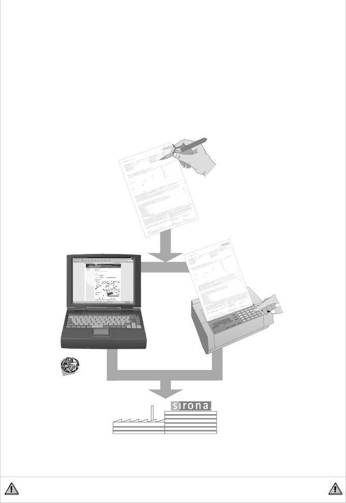
Das vorliegende Protokoll wird |
The present document is written |
Le présent document est établi |
El presente documento es |
durch den für die Installation |
by the engineer responsible for the |
conjointement par le technicien |
confeccionado por el técnico |
verantwortlichen Techniker und |
installation and the operator or a |
responsable de l’installation et |
responsable de la instalación y el |
dem Betreiber bzw. einer von |
person authorized by the operator. |
par l’exploitant ou une personne |
usuario y/o una persona por él |
ihm benannten Person ausge- |
The Installation Report / Warranty |
nommée par lui. |
nombrada. |
füllt. |
Pass can be completed and |
Vous pouvez nous renvoyer le |
El protocolo de montaje y el |
Das Ausfüllen und Versenden |
forwarded electronically via the |
protocole d'installation / fiche |
pasaporte de garantía se pueden |
des Installationsprotokolls / |
service offers located in the Dealer |
de garantie dûment rempli par |
rellenar y enviar utilizando las |
Garantiepasses kann elektro- |
domain of our Internet home page |
fax ou par voie électronique |
ofertas de servicio de la zona de |
nisch über die Serviceangebote |
or printed, filled out and faxed to |
dans l'ESPACE REVENDEURS |
distribuidores de la página Internet |
im Händlerbereich der Sirona- |
us. Based on this document, the |
(onglet SERVICE ) du site |
de Sirona, o bien por fax. Este |
Internet-Seiten oder konventio- |
installed unit is registered by |
internet Sirona. Ce document |
documento, con el que Sirona |
nell per Fax erfolgen. Anhand |
Sirona and is the basis for |
permettra à Sirona de gérer |
registra el equipo instalado, es la |
dieses Dokumentes wird das |
fulfillment of any warranty claims, |
l'appareil installé et servira de |
base para dictaminar sobre los |
installierte Gerät bei Sirona |
especially regarding extension of |
base pour répondre aux |
derechos de garantía, |
erfasst und stellt somit die |
the warranty period. |
éventuelles revendications de |
especialmente de las garantías |
Grundlage zur Erfüllung etwai- |
|
garantie, notamment de |
prorrogadas. |
ger Garantieansprüche, insbe- |
|
garantie étendue. |
|
sondere der erweiterten |
|
|
|
Garantie, dar. |
|
|
|
|
|
|
|
Bitte senden an:
Please send to:
À envoyer à:
Enviare a:
oder:
or:
ou: o
пппKлбкзе~KЗЙ
пппKлбкзе~KЕзг=
FAX:
++49(0)6251/16-1808
In USA please send to:
(704) 587-9394
|
Diese Unterlage ist keine Bestellunterlage für Ersatzteile! |
|
|
This document does not constitute an order form for spare parts! |
|
09/21/2006 |
Ce document n’est pas un formulaire de commande pur pièce de rechange! |
|
8/61 |
Servicemanual DAC Professional |
|
|
¡Este no es un documento para pedir piezas de repu sto! |
|
Maintenance instruction and protocol
DAC Professional
1Maintenance is to be performed every 2nd. Year or 2000 cycles.
2Important before maintenance:
2.1 |
Safety instructions: |
! |
• The autoclave is still under power also it is switched off (Mains switch, Fuse |
holders)! |
•For every work that leads to let raise the pressure in the chamber, the door must be closed safe. Check that the autoclave has locked the door (Tappet of the door lock prevents to open the door)!
Please have the user perform a vacuum test the morning you will perform the maintenance to shorten the time of work for the technician!
If the autoclave is connected to a water treatment system (aqua dem) e. g. SiroDem please perform the maintenance for this device also!
3 After the maintenance
Please make two extra copies of this service record.
The original will be kept in the doctor’s office, or in the clinic or hospital. The first copy will remain with the person who performs the service.
4 Data of Device
Serial-No: |
Year of production: |
|
|
___________________________________________ |
___________________________________________ |
||
|
|
|
|
Reading on the total-cycle counter: |
Number of successful cycles: |
|
|
___________________________________________ |
___________________________________________ |
||
|
|
|
|
Technician: |
Date: |
|
Time: |
___________________________________________ |
______________ |
from: ______ to: |
_______ |
|
|
||
Serviced by (company, depot, or specialized Sirona |
Name and address of doctor’s office, clinic, or hospital:: |
||
dealer): |
|
|
|
___________________________________________ |
___________________________________________ |
||
|
|
|
|
The above-stated person has performed the maintenance work according to the following service checklist:
The person performing the maintenance will make a check in the circle to show that he has
performed the step of work O : |
|
|
09/21/2006 |
9/61 |
Servicemanual DAC Professional |

Maintenance instruction and protocol
DAC Professional
5 Static Check
5.1 General instructions / Safety instructions
For the following service work, it is recommended to remove the lower part of the rear wall of the device, in addition to the housing. The DAC Professional will remain fully functional after these parts are removed. Warning: Be sure to observe the relevant safety precautions that must be observed for operating the device without the rear wall and the housing.
5.2 Check the levelling of the autoclave
Check to make sure the autoclave has been set up and positioned properly to slope to the rear. Starting from a level position, the front feet of the autoclave must be screwed three (3) turns for the DAC Professional. The autoclave must slope to the rear to ensure that the residual water and condensate will properly flow out toward the rear.
O Levelling was o.k. |
O Levelling corrected |
5.3 Check of the chamber and the tray rack
Check the chamber and the tray rack for dirt / rust.
The chamber should be checked at every use by the practice personnel.
Cleaning the chamber is not a part of the maintenance!
O O O
Chamber / Tray rack were clean
Chamber / Tray rack must be cleaned Chamber / Tray rack have been cleaned
5.4 Check the door gasket
Check the door gasket (rubber seal) to make sure that it is not damaged. Clean if required with a mild commercial liquid cleaning agent (pH = 5 … 8; the agent must NOT contain vinegar), or with spirits (alcohol).
O Gasket was clean O Gasket was cleaned
O Gasket has been exchanged
______________________________________________________________________
______________________________________________________________________
5.5 Adjustment of the door locking mechanism
See Instructions in the Service manual“ O Adjustment performed
5.6 Check / grease the door lock
Check the door lock for wear or defects. Lubricate with plain silicone grease.
O Door lock greased
O Following parts were exchanged: ________________________________________
09/21/2006 |
10/61 |
Servicemanual DAC Professional |

Maintenance instruction and protocol
DAC Professional
5.7 Check the door hinges for correct play
The play is too excessive when the door knocks against the door latch when closed and the door must be lifted to be closed.
O Slight play
O Following parts exchanged because of excessive play: ________________________
5.8 Check the retaining rings of the bolts of the door hinge
Both of the hinge bolts must be secured against sliding out of place, by the use of retaining rings on the top and lower sides of each bolt.
O Retaining rings OK
O Retaining rings / bolts were exchanged
5.9 Check / Adjustment of the door contact switch
Check and adjust the door contact (there should be 1 ... 2 mm from the display “Door closed” to the lower limit).
O Adjustment is o.k. O Adjustment corrected
5.10Cleaning the cooler / fan / cooler ribs
To do this, completely disassemble the cooler and the fan, and clean the cooler ribs and the fan on both sides with a vacuum hoover. Here it is necessary to disconnect the hose connections, the tightening clamps of the cooler, the mounts of the blower, and the electrical connections to the solenoid valves and fan. Then dust and clean the cooler ribs.
O Done.
5.11Exchange the sterile filter
During every maintenance the sterile filter order no: 6126093 must be exchanged.
O Done
5.12Check the pressure-release filter
Remove the sieve inserts for both pressure-release filters and clean them. Exchange if necessary. The cap nuts must be unscrewed to remove the filter inserts. These nuts are freely accessible without further disassembly of the autoclave. Helpful hint: place the autoclave between two tables for your work.
O Cleaned O Exchanged
09/21/2006 |
11/61 |
Servicemanual DAC Professional |

Maintenance instruction and protocol
DAC Professional
5.13Check of the electrical connections
Check to make sure that the cables are tightly connected. Make sure to carefully check the power-conducting tab connectors (tab-and-receptacle connections) that are listed below:
CHECKED:
O Mains switch
O Mains fuses / holders
O The proper power-supply voltage on the main board of the electronic control system
O Output of steam generator (ACOUT1) and power-voltage feed (LL, N) on the CPUboard.
O Overheating protection for the steam generator O Overheating protection for the Preheating
O Tighten the screw connections for all rectifier plugs
5.14Check all hoses inside the autoclave
Check all hoses on the inside of the device to make sure that they are not damaged, and that they are in correct position.
Tighten to finger tightness, and then use an engineer's wrench to turn one-half turn more
(½).
O Hoses and connections are o.k. O Connections tighened
6 Functional check
6.1 Run a program "Vacuum-Test"
Carry out the Vacuum Test program with a cold autoclave (if possible by the practice before the maintenance).
Attach the test printout at the end of this report.
Read the leak rate from the printout and the time that was used for the evacuation or note it below.
Check and evaluate the vacuum-pump performance on the basis of the evacuation time
required for the vacuum test. Maximum time for vacuum evacuation tmax = 2 min. Actual time required: ……….. min. If the time is exceeded check the autoclave for leakages, function of the solenoid valves and the performance of the vacuum pump.
Leak rate = __________________ mbar/min
Time for evacuation= ___________ min O O.K.
O Works done: ________________________________________________________
09/21/2006 |
12/61 |
Servicemanual DAC Professional |

Maintenance instruction and protocol
DAC Professional
6.2 Run a test cycle "Quick-Program"
Carry out the Fast Program with unwrapped objects. You can stop the drying phase after 2 minutes to save time. Print out the test results and enclose with this service report.
Check all connections for leakages during the sterilization cycle when the chamber has built up a pressure.
Make an acoustic check during the test run for unusual noises (e. g. Clattering of lose parts when autoclave vibrates.) If there are unusual noises caused by the vacuum pump e. g. from the cavitation jet, exchange it. Add a protocol print-out and the indicator strip of the helix-test in the below mentioned field at the end of this report.
Add the protocol print-outs (stick them in the fields at the end of this protocol) O Leakages checked
O Acoustic check performed
O Works done: _________________________________________________________
7 Reset the maintenance counter
Resetting as described in the separate Instruction.
O Done
09/21/2006 |
13/61 |
Servicemanual DAC Professional |

Maintenance instruction and protocol DAC Professional
8 Confirmation
O O
The maintenance was successfully performed
The maintenance was not successfully because of the following:
___________________________________________________________________
___________________________________________________________________
___________________________________________________________________
Additional notes:
______________________________________________________________________
______________________________________________________________________
______________________________________________________________________
We confirm that the maintenance has been performed in accordance to the above mentioned instruction.
__________________________________________ |
___________________________________________ |
Signature of the service technicians |
Signature / Stamp of the practice / clinic |
9 Protocol Print-outs
9.1 Vacuum-Test:
9.2 Quick-Program:
09/21/2006 |
14/61 |
Servicemanual DAC Professional |
Fault diagnosis for DAC Professional
Fault 1: Vacuum system
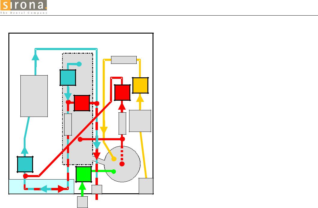
CONFIGURATION OFCOMPONENT GROUPS IN THE AUTOCLAVE
ERROR 1 VACUUM UNIT
DAC Professional Configuration of the component |
FRONT |
groups in the autoclave (TOP VIEW) |
|
SQ1
VV1 K
PV
VDA2
F
VQ |
VDA1 |
F PQ
K |
|
VV2 |
|
VB |
H1 |
C |
SLW |
F |
|
This overview shows a rough schematic of the spatial configuration of the component groups, pipes, and hoses, in the DAC Professional. The following error descriptions will refer to this overview to help you find the component groups to be checked.
Item |
Bezeichnung |
Description |
State of valve |
ACOUT |
|
|
|
when no |
(power |
|
|
|
current is |
output) |
|
|
|
|
|
|
|
|
applied (dead) |
|
C |
Kühler |
cooler |
|
4 |
F |
Filter |
filter |
|
|
H 1 |
Dampferzeuger |
steam generator |
|
1 |
K |
Kessel |
vessel |
|
|
P Q |
Pumpe aqua dest |
pump for distilled water |
|
5 |
P V |
Vakuumpumpe |
vacuum pump |
|
3 |
S LW |
Sensor Leitwert |
sensor for conductivity |
|
|
S Q1 |
Strömungswächter |
flow sensor for dist. water |
|
|
V |
Ventil (Magnet~) |
valve (solenoid) |
|
|
VB |
Belüftung |
ventilation |
open |
8 |
V DA1 |
Druckablaß 1 |
pressure release 1 |
closed |
7 |
V DA2 |
Druckablaß 2 |
pressure release 2 |
closed |
9 |
VQ |
Speisewasser aqua dest |
feed water (distilled) |
closed |
5 |
VV1 |
Vakuum 1 |
vacuum 1 |
closed |
6 |
VV2 |
Vakuum 2 |
vacuum 2 |
closed |
6 |
09/21/2006 |
15/61 |
Servicemanual DAC Professional |

Fault diagnosis for DAC Professional
Fault 1: Vacuum system
Tripping conditions:
Fault conditions may occur if the monitoring time Uet1 was exceeded for achievement of the following:
•The required evacuation pressures for the individual sub-atmospheric pulses
–P37, P38, P40, P41 for cold starts
–P1, P2, P21, P22 for hot starts
•The required evacuation pressure (P17) for the vacuum test
•The required evacuation pressure (P12) for evacuation / pressure relief
•The required minimum pressure for drying (P3).
Causes of the problem / Correction of the problem
Action / checking by operating staff:
•Check for defects and for soiling of the door seal and the sealing surfaces of the sterilization chamber, and on the round plate around the door of the sterilization chamber. Repair and clean if necessary.
•Check to make sure that the autoclave is properly set up (it must be installed with a tilt (at slope), as described in the operating instructions).
•Check to make sure that the condensate drain at the bottom of the sterilization chamber is not stopped. It can be stopped if instruments, filter paper, etc. fall onto the bottom of the chamber.
•Check for the following:
–If you are using the internal system for supply of demineralised water, check to make sure that the pressure-release pipe is not stopped.
–If you are using an external waste-water connection that empties into the building waste-water system, check to make sure that this drain pipe does not have a kink (make sure the water can flow freely out).
09/21/2006 |
16/61 |
Servicemanual DAC Professional |

Fault diagnosis DAC Professional
Fault 1: Vacuum system
Faults in the autoclave / Correction of faults by technical service personnel
Fault 1
Vacuum system
|
|
|
|
Note: |
|
|||
|
|
|
|
|
||||
Start the vacuum test |
||||||||
|
|
|
|
|
|
|||
|
|
|
|
|
|
|
||
Is the vacuum pump |
|
|
|
|
|
|
||
|
|
No |
|
|
||||
|
|
|
|
|||||
running? |
|
|
|
|
||||
|
|
|
|
|
|
|||
|
|
|
|
|
|
|||
|
|
|
|
|
|
|
||
Yes |
|
|
|
|
|
|
|
|
|
|
|
|
|
|
|
|
|
Vacuum test OK? |
No |
(Leak rate < 1.3 mbar/min)
Yes
Important: All vacuum tests must be conducted with a cold, dry autoclave. Watch the evacuation pressure achieved here and the pressure change over time (from the display).
Æ Fault Class: Control fault / faulty pump please check the following for faults: power output ACOUT3; fuse F1; possibly defective vacuum pump. Correct the fault, and then go to next.
Vacuum test OK Leak rate OK Pressure is stable
Leak rate is too great |
|
"Fault 31: System leaks" |
|
"Fault 1: Vacuum |
(> 1.3 mbar) and permanent |
|
Pressure rise over P3 |
|
system" |
pressure rise |
|
(very large leaks) |
|
|
|
|
|
|
|
|
|
|
No |
|
||
Special vacuum test OK? |
Æ Fault Class: Leak fault |
|||||
|
|
|||||
(System flag F11 = 1) |
|
|
Repair the leak in the intake |
|||
(Pressure stable?) |
|
|
line; then next |
|||
Yes |
|
|
|
|
|
|
Æ Fault Class: Vacuum fault
Pump system too weak Correct fault and go on with normal program start.
Æ Fault Class: Leak fault
Stop the leaks and then next
The sub-atmospheric |
Sub-atmospheric |
pressure achieved is very |
pressure is within the |
weak, or the pressure is |
range of moderate to |
the same as in the room. |
just less than the |
|
evacuation pressure |
|
(P17) |
|
In the Service Program, raise the evacuation pressure (P17) for the vacuum test by approx. 20 mbar more than |
|
|
|
the evacuation pressure reached during the first test. Then repeat the test. (Important: When changing |
|
|
|
P17, make sure that P13 is always greater than P17. If necessary, also raise 13 to ensure that P13 > |
|
|
|
P17. If this is not done, you will receive the error message “System leak”.) |
|
|
09/21/2006 |
|
|
DAC Professional |
17/61 |
Servicemanual |
||

Fault diagnosis for DAC Professional
Fault 1: Vacuum system
Fault 1: Vacuum system
Æ Fault class: Fault in control system or function of the pump
You can check the input voltage for the vacuum pump, as well as the function of the pump, as follows:
Make sure that the intake side is vented, since the pump will not start against a vacuum. In the Diagnosis program, switch on the solenoid valves for vacuum 1 + 2 (VV1 + VV2) by switching on the power output ACOUT 6 (the valves are open when the current is applied).
In the Diagnosis Program, switch on the pump |
|
No |
|
Check Fuse F1. Is it OK? |
(PV) by switching the power output ACOUT 3. |
|
|
|
|
Does the pump now run? |
|
|
|
|
|
|
|
|
Yes |
Yes |
|
|
|
|
|
|
|
Test the power output |
|
|
|
|
|
|
|
|
|
|
EP2-2 on the circuit board |
Proceed to the next step in the higher-level |
|
|
|
|
|
|
|
with a meter. Output OK? |
|
fault-analysis plan. |
|
|
|
|
|
|
|
Yes |
|
|
|
|
|
|
|
|
|
|
|
|
|
|
|
|
|
|
|
|
The pump is defective. |
|
|
|
|
Exchange the pump. |
|
|
|
|
|
No Exchange
fuse F1.
No Exchange the
circuit board.
Æ Fault class: the vacuum performance of the pump system is too weak
► The vacuum solenoid valves 1 + 2 do not open (VV1, VV2)
•The solenoid valve, or coil, or rectifier plugs are defective.
•The activation for the solenoid valve (output 6) is defective.
Switch on output 6 in the Diagnosis program.
Check the electric control system and the switching behavior of the solenoid valve.
►The flow resistance in the intake line is too high
•Filter in the intake fitting on the sterilization chamber is clogged up
►The pressure-sensor signal is defective, or the processing of this signal is not correct
•The level of the pressure-sensor signal, or the signal processing, is too high. See the section “Sensor Fault Group”.
►The suction of the vacuum pump is too weak
Check the vacuum performance of the membrane as follows:
1.Check to see if there are leaks.
2.Make sure that the chamber to be evacuated is empty and dry.
3.If there are no leaks, and if the chamber is empty and dry, check the performance of the pump. It must be at least 800 mbar in 80 s, or 900 mbar in 180 s.
4.If there are no leaks, and if the chamber is empty and dry, and if the performance of the pump does not meet the above level (800 mbar in 80 s, or 900 mbar in 180 s), then exchange the pump.
09/21/2006 |
18/61 |
Servicemanual DAC Professional |
 Loading...