


 Loading...
kÉï=~ë=çÑW== |
MPKOMMU |
`bob`=L=áåi~Ä=j`=ui |
|
pЙкобЕЙ=j~ем~д= |
|
|
bеЦдблЬ |

Sirona Dental Systems GmbH |
|
Service Manual CEREC / inLab MC XL |
Contents |
Contents
1
2
General information ................................................... |
7 |
|
1.1 |
General information ........................................... |
8 |
1.2 |
Additional information ........................................ |
9 |
Description of the service software.......................... |
12 |
|
2.1 |
General information ........................................... |
13 |
2.2 |
Basic structure of test dialogs ........................... |
14 |
2.3 |
Individual Test Points ........................................ |
19 |
2.3.1 |
Serial Communication..................................... |
19 |
2.3.2 |
Media supply .................................................. |
20 |
2.3.3 |
Light Barriers, Door Switch, Temperature Sensor and |
|
|
Motor Stop Positions....................................... |
21 |
2.3.4 |
Stepping motor test ........................................ |
23 |
2.3.5 |
Stepping motors - Single step......................... |
24 |
2.3.6 |
Stepping motor - Step response..................... |
26 |
2.3.7 |
DC motors 'Load/inlet'..................................... |
27 |
2.3.8 |
DC motors 'Touch' .......................................... |
28 |
2.3.9 |
DC motors 'Speed'.......................................... |
29 |
2.3.10Sensor test ..................................................... |
30 |
|
2.3.11Force sensor test............................................ |
31 |
|
2.3.12Continuous load.............................................. |
32 |
|
2.3.13Camera quick test........................................... |
32 |
|
2.3.14Milling Unit Info ............................................... |
39 |
|
3 Troubleshooting ......................................................... |
42 |
|
3.1 |
Force measurement errors ................................ |
43 |
3.2 |
Stepping motor does not move ......................... |
44 |
3.3 |
Faulty locking of block chuck ............................. |
46 |
3.4 |
DC motor does not lock ..................................... |
47 |
3.5 |
Milling instruments come loose ......................... |
48 |
3.6 |
Milling chamber door switch .............................. |
49 |
3.7 |
Unit switches off ................................................ |
50 |
3.8 |
Tank switch defect ............................................. |
52 |
3.9 |
Edges break off ................................................. |
53 |
3.10 |
Insufficient air pressure ..................................... |
55 |
3.11 |
Holes in restoration ........................................... |
56 |
3.12 |
Stepping motor cannot be controlled ................. |
57 |
3.13 |
Faulty water pressure ........................................ |
58 |
3.14 |
Unit cannot find starting position ....................... |
60 |
61 83 292 D 3439 |
|
|
D 3439.076.01.02.02 03.2008 |
|
3 |

|
Sirona Dental Systems GmbH |
Contents |
Service Manual CEREC / inLab MC XL |
|
|
3.15 |
Unit cannot be turned on ................................... |
61 |
|
3.16 |
Touch errors ...................................................... |
62 |
|
3.17 |
Service life of milling instruments too short ....... |
63 |
|
3.18 |
Milling unit not addressable ............................... |
64 |
|
3.19 |
LAN communication problems .......................... |
65 |
|
3.20 |
WLAN connection occasionally interrupted ....... |
67 |
|
3.21 |
WLAN communication problems ....................... |
68 |
|
4 Repair |
.......................................................................... |
70 |
|
4.1 |
Removing/attaching ...............................covers |
72 |
|
4.2 |
Replacing ...................the (DC) spindle motors |
74 |
|
4.2.1 ............................................. |
DC motor, single |
74 |
|
4.2.2 ........................................... |
DC motor, double |
79 |
|
4.2.3 ...............Testing and setting the DC motor(s) |
84 |
||
4.2.4 ................Chuck of milling instrument broken |
85 |
||
4.3 |
Replacing/retrofitting .....................the scanner |
86 |
|
4.3.1 ......................................................... |
Removal |
86 |
|
4.3.2 ...................................................... |
Installation |
87 |
|
4.3.3 ..................... |
Testing and setting the scanner |
88 |
|
4.4Replacing the controller board / microcontroller module 88
4.5 |
Replacing the WLAN module ............................ |
91 |
|
4.6 |
Replacing the milling chamber lighting .............. |
91 |
|
4.7 |
Replacing stepping motors ................................ |
92 |
|
4.7.1 |
BR stepping motor.......................................... |
92 |
|
4.7.2 |
GR / MR stepping motor................................. |
93 |
|
4.8 |
Replacing the milling machine .......................... |
94 |
|
4.8.1 Removing the milling machine........................ |
94 |
||
4.8.2 Installing the milling machine.......................... |
96 |
||
4.9 |
Replacing the tank switch ................................. |
97 |
|
4.9.1 |
Preparations ................................................... |
97 |
|
4.9.2 Removing the chassis insert........................... |
98 |
||
4.9.3 Replacing the tank switch............................... |
100 |
||
4.9.4 Installing the chassis insert............................. |
100 |
||
4.9.5 |
Final work ....................................................... |
101 |
|
4.10 Replacing the suction connection ..................... |
101 |
||
4.10.1Preparations ................................................... |
101 |
||
4.10.2Removing the chassis insert........................... |
102 |
||
4.10.3Replacing the suction connection................... |
102 |
||
4.10.4Installing the chassis insert............................. |
102 |
||
4.10.5Final work ....................................................... |
102 |
||
4 |
61 83 292 D 3439 |
D 3439.076.01.02.02 03.2008 |
|
|
|

Sirona Dental Systems GmbH |
|
|
Service Manual CEREC / inLab MC XL |
|
Contents |
4.11 |
Replacing the light barrier ................................. |
102 |
4.12 |
Replacing the milling chamber door .................. |
103 |
4.13 |
Replacing the air pump ..................................... |
104 |
4.14 |
Replacing the pressure switch .......................... |
105 |
4.14.1Water pressure switch .................................... |
105 |
|
4.14.2Air pressure switch ......................................... |
105 |
|
4.14.3Air pressure sensor (CEREC MC XL only) ..... |
106 |
|
4.15 |
Replacing the fan unit ........................................ |
106 |
4.16 |
Replacing the cooling pack ............................... |
107 |
4.17 |
Replacing the water pump ................................. |
108 |
4.18 |
Replacing the display ........................................ |
110 |
4.19 |
Adjusting the plunger pin ................................... |
110 |
4.19.1G-axis and M-axis plunger pin........................ |
110 |
|
4.19.2B-axis plunger pin........................................... |
111 |
|
4.20 |
Replacing the block fastener ............................. |
113 |
5 Cleaning the chucks................................................... |
116 |
|
5.1 |
Block chuck and block clamping nut ................. |
117 |
5.2 |
Milling instrument chucks .................................. |
120 |
61 83 292 D 3439 |
5 |
D 3439.076.01.02.02 03.2008 |

General information
CEREC / inLab MC XL

Sirona Dental Systems GmbH |
|
1 General information |
Service Manual CEREC / inLab MC XL |
|
|
|
1 General information |
|
|
Contents |
|
1.1 |
General information ........................................................... |
8 |
1.2 |
Additional information ....................................................... |
9 |
61 83 292 D 3439 |
7 |
D 3439.076.01.02.02 03.2008 |

1 General information |
Sirona Dental Systems GmbH |
General information |
Service Manual CEREC / inLab MC XL |
|
|
Nominal line voltage ranges
Wireless phone interference with medical electrical equipment:
ESD warning label
ESD protective measures
Measurements
When replacing parts
1.1General information
The CEREC MC XL / inLab MC XL milling unit can be operated in the following
znominal line voltage ranges: 100 - 230VAC; 50 / 60 Hz
 NOTE:
NOTE:
To ensure safe operation of medical electrical equipment, the use of mobile wireless phones in practice or hospital environments is prohibited.
 CAUTION:
Connector pins or sockets bearing ESD warning labels must not be touched or interconnected without ESD protective measures.
ESD protective measures include:
zProcedures for preventing electrostatic charge build-up (e.g. air conditioning, air moistening, conductive floor coverings and non-synthetic clothing)
zDischarging the electrostatic charges of your own body on the frame of the unit, the protective ground wire or large metallic objects
zConnecting yourself to ground using a wrist band.
Always switch off the unit before connecting the measuring instrument.
Select the correct current/voltage type and adjust the measuring range to match the expected readings.
Perform continuity tests only on units which are switched off.
 WARNING: Potentially lethal shock hazard when working near the power supply unit
Disconnect from the line power supply. Check for zero potential.
Switch the unit off and disconnect the power plug before replacing parts.
The article numbers for ordering spare parts can be found in the spare parts list, Order No. 61 45 853.
The diagrams contained in the spare parts list provide a useful guide when replacing parts.
Before replacing the boards, observe the ESD protective measures.
Disposal |
Observe the information on disposal in the relevant operating instructions. |
8 |
61 83 292 D 3439 |
D 3439.076.01.02.02 03.2008 |
|
|
|

Sirona Dental Systems GmbH |
1 General information |
Service Manual CEREC / inLab MC XL |
Additional information |
|
|
Installation site |
Observe the information on the installation site in the relevant operating |
|
instructions. |
1.2 Additional information
In addition, you also require:
CEREC / inLab MC XL spare parts list
Order No.: „61 45 853“
CEREC / inLab MC XL wiring diagrams
Order No.: „61 39 278“
CEREC / inLab MC XL Operating Instructions
CEREC MC XL, Order No.: "61 46 885" inLab MC XL, Order No.: "61 39 237"
Documents:
Operating the MC XL via LAN (61 90 503)
Operating MC XL via WLAN in the Ad-hoc mode (61 90 545)
Operating MC XL via WLAN in infrastructure mode, Restoring default settings (61 90 560)
Tools
zAllen key angled, size (mm) 1.27 (0.05”); 1.3;6
zOpen-end wrench, size (mm) 6;10
zTORX screwdriver, size 6; 8; 10; 20
zPhillips screwdriver, size 1
zBlade screwdriver, insulated, sizes 2 and 3
zBox wrench: 6mm; 7mm
zUniversal pliers
zFlat pliers
zTorque wrench, 1.1Nm
zFeeler gauge 0.1mm
61 83 292 D 3439 |
9 |
D 3439.076.01.02.02 03.2008 |

1 General information |
Sirona Dental Systems GmbH |
Additional information |
Service Manual CEREC / inLab MC XL |
|
|
Auxiliary tools & equipment
zDigital Multimeter, Accuracy Class 1
zSoldering tool for repairing cables
zDiagonal-nosed cutting pliers
zCable ties
zTeflon tape
zLoctite 221
zCalibration set (supplied with unit)
zStep Bur 12 and Step Bur 20
zTorque wrench for changing the milling instruments (order no: 61 19 346)
zFuses (recommended):
F1 (2 pcs) |
T5H250V |
Order No.: 20 33 111 |
10 |
61 83 292 D 3439 |
D 3439.076.01.02.02 03.2008 |
|
|
|
Description of the service software
CEREC / inLab MC XL

2 Description of the service software |
|
Sirona Dental Systems GmbH |
|
Service Manual CEREC / inLab MC XL |
|
2 |
Description of the service software |
|
Contents |
|
|
2.1 General information ........................................................... |
13 |
|
2.2 Basic structure of test dialogs.......................................... |
14 |
|
2.3 Individual Test Points ........................................................ |
19 |
|
2.3.1 |
Serial Communication ........................................ |
19 |
2.3.2 |
Media supply ...................................................... |
20 |
2.3.3 |
Light Barriers, Door Switch, Temperature Sensor and |
|
|
Motor Stop Positions .......................................... |
21 |
2.3.4 |
Stepping motor test ............................................ |
23 |
2.3.5 |
Stepping motors - Single step ............................ |
24 |
2.3.6 |
Stepping motor - Step response ........................ |
26 |
2.3.7 |
DC motors 'Load/inlet' ........................................ |
27 |
2.3.8 |
DC motors 'Touch'.............................................. |
28 |
2.3.9 |
DC motors 'Speed' ............................................. |
29 |
2.3.10 Sensor test ........................................................ |
30 |
|
2.3.11 Force sensor test............................................... |
31 |
|
2.3.12 Continuous load ................................................ |
32 |
|
2.3.13 Camera quick test ............................................. |
32 |
|
2.3.14 Milling Unit Info.................................................. |
39 |
|
12 |
61 83 292 D 3439 |
D 3439.076.01.02.02 03.2008 |
|
|
|

Sirona Dental Systems GmbH |
2 Description of the service software |
Service Manual CEREC / inLab MC XL |
General information |
|
|
|
2.1 |
General information |
Test requirements |
Requirement for all tests: |
|
|
z PC / acquisition unit is switched on and ready for operation. |
|
|
z PC / acquisition unit and milling unit are interconnected (via network cable |
|
|
|
or WLAN) |
|
z The door of the milling chamber must remain closed as long as any |
|
|
|
motors or the water pump are running. If the door of the milling chamber is |
|
|
opened during the test, all motors and the water pump will switch off |
|
|
immediately (same function as pressing the "STOP" button). |
|
z The tools (burrs) must be installed already during operation of the water |
|
|
|
pump. |
|
z During operation of the water pump, the air pump mustalways be running |
|
|
|
to protect the DC motors against water damage, i.e. the air pump is |
|
|
started first. If the air pressure switch detects no air pressure, an error |
|
|
message will appear and the test cannot be performed. |
Service software log file |
The Service software generates a log file for all tests performed. This log file |
|
|
is located in the folder on delivery. |
|
|
c:\programme\Cerec\System\Service\Protocols and is named |
|
|
Testdatei_XXXXXXXXXXXX.TXT |
|
|
The Xs here denote the serial no. of the milling unit. |
|
|
Each time the service software is started, a confirmation query appears |
|
|
asking whether this file (if it already exists) should be deleted. If "No" (do not |
|
|
delete) is selected, the tests subsequently performed will be appended to the |
|
|
ones previously saved. Each test is labeled with a starting and ending date. |
|
|
The test file can be viewed with the editor at any time. If the user quits a test |
|
|
without saving it, he will be asked if he really wants to quit without saving. If |
|
|
"Yes" (Quit without saving) is then selected, the data just measured will be |
|
|
lost. |
|
Assessment scores |
There are three different scores which can be assigned to test results: |
|
|
z |
passed fully ("Passed fully", (green label) |
|
z passed ("Passed", yellow label) |
|
|
z |
not passed ("Not passed", red label) |
The area which passed may be irrelevant for a specific test. In that case, n.a. (not applicable) will be written to the log file for this area.
 NOTE: Assessment scores
Passed fully: If all test results are scored "Passed fully", flawless operation of the system is possible.
Passed: If the test results are scored"Passed", uncritical changes have occurred.
Not passed: If the test results are scored "Not passed", you must find and eliminate the cause.
 CAUTION: Keep the cover closed
If the milling unit housing is left open, the temperature switch on the controller board may cut out after a short time (T>90°C). The cooling fan can work properly only with the cover closed.
61 83 292 D 3439 |
13 |
D 3439.076.01.02.02 03.2008 |

2 Description of the service software |
Sirona Dental Systems GmbH |
Basic structure of test dialogs |
Service Manual CEREC / inLab MC XL |
|
|
Milling chamber
Milling chamber |
|
|
|
A |
Scanner |
E |
Bur Set 2 |
B |
Scanner window |
F |
Ceramic block |
C |
Motor mount |
G |
Workpiece spindle |
D |
Bur Set 1 |
H |
Block clamping nut D6/D10 |
 NOTE: Availability of the test options
Some tests (e.g. motor set 2) are selectable only with inLab MC XL or with
CEREC MC XL with a second bur set (optional).
2.2Basic structure of test dialogs
|
NOTE: Damage to system |
|
The Service functions may be used only by authorized service engineers |
|
who have been trained by Sirona. |
Password |
|
The service software test dialogs are protected by a password to prevent |
|
|
manipulations by unauthorized users. |
|
The password has four digits. It changes daily and is generated from the |
|
system date of the computer according to the following scheme: |
Password |
Generated from |
number |
|
|
|
1 |
2. number of the current month |
|
|
14 |
61 83 292 D 3439 |
D 3439.076.01.02.02 03.2008 |
|
|
|

Sirona Dental Systems GmbH |
2 Description of the service software |
Service Manual CEREC / inLab MC XL |
Basic structure of test dialogs |
|
|
Password |
Generated from |
number |
|
|
|
2 |
1. number of the current month |
|
|
3 |
2. number of the current day |
|
|
4 |
1. number of the current day |
|
|
Example: 02/28/2007 becomes 2082
 CAUTION: Do not disclose the password scheme
Do not disclose the password creation scheme to others.
Before entering the password, always determine the date as inconspicuously as possible.
Since the password is always valid for one single day only, it can be passed on to the user in exceptional cases, e.g. to provide immediate telephone support.
 NOTE: Password input errors
|
If the commands are not enabled after you enter the password, check the |
|
following: |
|
- correct entry of the password, |
|
- the system date set on the computer. |
|
The dialog for setting the system time can be called up in all Windows |
|
operating systems by double-clicking the time displayed in the systray. |
Opening the Service software |
1. Open the Service menu as follows. |
|
CEREC MC XL: |
|
"Start"/"Programs"/"CEREC"/"Service" |
|
inLab MC XL: |
|
"Start"/"Programs"/"inLab"/"Service" |
|
ª The Service Login dialog box then opens for password entry. |
2.Enter the password and confirm your entry with the "Yes" button.
61 83 292 D 3439 |
15 |
D 3439.076.01.02.02 03.2008 |

2 Description of the service software |
Sirona Dental Systems GmbH |
Basic structure of test dialogs |
Service Manual CEREC / inLab MC XL |
|
|
 NOTE: Select the milling unit
If there is no data link between the milling unit and the acquisition unit / PC or several milling units are connected, the "Select milling unit" dialog box will open.
¾Establish a data link if necessary.
¾Click the "Add automatically" button.
ªThe acquisition unit / PC installs the milling unit.
¾Select the relevant milling unit and confirm your choice with the "OK" button.
Log file |
If a log file with the name of the milling unit you have selected already exists, |
|
you will be asked if you want to delete this file. |
zClick the "Yes" button:
The old file is then deleted and a new log file is created.
zClick the "No" button:
The old file is then not deleted and the data from the new test run is appended to it.
16 |
61 83 292 D 3439 |
D 3439.076.01.02.02 03.2008 |
|
|
|

Sirona Dental Systems GmbH |
2 Description of the service software |
Service Manual CEREC / inLab MC XL |
Basic structure of test dialogs |
|
|
Test selection dialog box
ATests performed only at the factory
In the "Test selection"dialog box you can select
za test for the complete milling unit ("Total test") or
zan individual test.
The selected test dialog box then opens if you click "OK".
61 83 292 D 3439 |
17 |
D 3439.076.01.02.02 03.2008 |

2 Description of the service software |
Sirona Dental Systems GmbH |
Basic structure of test dialogs |
Service Manual CEREC / inLab MC XL |
|
|
Example: Total test
Total test
A |
Number of test runs completed since the last time the Start |
|
|
button was actuated. |
|
|
|
|
B |
Progress bar for test currently being run. |
|
|
|
|
C |
Check boxes for selecting (activating/deactivating) the tests |
|
|
available in this test dialog. |
|
|
|
|
D |
Check box for selecting the options possible in this test dialog. |
|
|
|
|
E |
Number of test results since the last start: |
|
|
|
Passed fully |
|
|
Passed |
|
|
Not passed |
|
|
|
F |
Pressing the "Start" button starts the test run with the |
|
|
selected settings. The test run is repeated until it is cancelled |
|
|
by pressing the "Stop" button. The test run counter is then |
|
|
reset to 0. Once started, the test run can be halted only with |
|
|
"Stop". No other inputs are possible during the test run. |
|
G |
The test is canceled as soon as possible with the "Stop" |
|
|
button. The test in progress at the time of cancellation is not |
|
|
counted. All inputs are now possible again. |
|
|
|
|
18 |
61 83 292 D 3439 |
D 3439.076.01.02.02 03.2008 |
|
|
|

Sirona Dental Systems GmbH |
2 Description of the service software |
Service Manual CEREC / inLab MC XL |
Individual Test Points |
|
|
H |
All existing data can be saved to the log file by pressing the |
|
"Save" button. The data are appended to the previously |
|
existing log file (if the current test run has not yet been saved). |
|
If no data exist, a message to that effect will appear (confirm |
|
with "OK"). Once a test run has been saved to the log file, a |
|
new test run must be started before selecting the save function |
|
again. |
|
|
I |
Press "Back" to quit the test dialog and return to the service |
|
dialog. If any data exist and have not yet been saved, you will |
|
be asked whether or not the test data should be saved. |
|
|
J |
Result: |
|
No color: No measurement available yet. |
|
green: Test passed fully. |
|
yellow: Test passed. |
|
red: Test not passed. |
|
|
2.3Individual Test Points
2.3.1 Serial Communication
The test is primarily used to measure the speed and quality of data transmission. This is especially important if the system is not operated via the network cable (LAN) but rather via other types of connections such as e.g. WLAN (AdHoc, Infrastructure.
The transmission time between the beginning of transmission and the end of reception is calculated for a specific record on the PC. A test run comprises one complete transmission in both directions.
The values thus measured are then saved to the log file.
Serial Communication |
|
|
|
1 |
Result of last test run |
3 |
Average measured |
|
|
|
transmission time |
2 |
Minimum measured |
4 |
Maximum measured |
|
transmission time |
|
transmission time |
61 83 292 D 3439 |
19 |
D 3439.076.01.02.02 03.2008 |

2 Description of the service software |
Sirona Dental Systems GmbH |
Individual Test Points |
Service Manual CEREC / inLab MC XL |
|
|
Typical values
|
Time |
|
|
LAN |
200 - 400 ms |
|
|
WLAN |
300 - 600 ms |
|
|
|
2.3.2 Media supply |
Purpose of Test: |
To check the media supply (air, water, fan) for proper functioning and test the |
|
pressure switches and the function of the pump. |
Procedure |
The pumps and the fan are switched on by nominal select control depending |
|
on selection. The motor currents and the condition of the pressure switches |
|
are registered. The points of time when the pressure detectors respond are |
|
measured. After approx. 5 sec the pumps are switched off and the time |
|
required until the pressure switch responds is measured and evaluated. |
Save |
Save stores the measured values to the log file under the heading of Media |
|
supply. |
|
Media supply |
|
Deviations of measurements |
Deviations may occur: |
|
|
z During the first test run (if any air is still in the water circuit) |
|
|
z |
If the amount of water in the water tank is insufficient |
|
z |
After filling the water tank. |
20 |
61 83 292 D 3439 |
D 3439.076.01.02.02 03.2008 |
|
|
|
Sirona Dental Systems GmbH |
2 Description of the service software |
Service Manual CEREC / inLab MC XL |
Individual Test Points |
|
|
|
2.3.3 Light Barriers, Door Switch, Temperature |
|
Sensor and Motor Stop Positions |
Purpose of Test: |
This test serves to evaluate the safe functioning of the light barriers and check |
|
the door switch, the temperature sensor and the motor stop positions. |
Light barrier |
When the end position is located, the slot of the gear is measured via the |
|
width and height at which the stepping motor positions are registered with the |
|
flanks. |
|
The light barriers to be tested can be selected in all variations. If no light |
|
barrier is selected, the Start button is not active. Default setting: All light |
|
barriers selected. |
|
Switch - light barrier |
Door switch/Tank switch |
The current state of the door switch and tank switch can be checked via a |
|
status bar display. |
|
Switches - Door and tank switch |
Control keys |
The current state of the control keys can be checked via a status bar display. |
61 83 292 D 3439 |
21 |
D 3439.076.01.02.02 03.2008 |

2 Description of the service software |
Sirona Dental Systems GmbH |
Individual Test Points |
Service Manual CEREC / inLab MC XL |
|
|
|
Switches - Control keys |
|
Display / Illumination |
The selected pattern is shown on the display as a display test. |
|
|
The "Illumination" button tests all colors of the milling chamber illumination: |
|
|
z white (milling, default color) |
|
|
z |
blue (scanning) |
|
z |
green (operation completed) |
|
z red (error / Stop button pressed) |
|
Switches - Display / Illumination
Adjustment


 ATTENTION: Open block / Close block
Place a block in the block axle to test the Open block / Close block function.
The motors are moved to these positions to test the motor stop positions. Depending on which button is selected, the motors move to the corresponding position and stop there. The motors can be reset to their home positions by pressing the "Home" button.
22 |
61 83 292 D 3439 |
D 3439.076.01.02.02 03.2008 |
|
|
|

Sirona Dental Systems GmbH |
2 Description of the service software |
Service Manual CEREC / inLab MC XL |
Individual Test Points |
|
|
Switches - Adjustment |
|
|
|
A |
Home position |
D |
Stop position for tool |
|
|
|
change (set 2) |
B |
Stop position for tool |
E |
Open block |
|
change (set 1) |
|
|
C |
Aux. position for replacing |
F |
Close block |
|
components |
|
|
|
2.3.4 Stepping motor test |
|
Purpose of Test: |
|
This test serves to evaluate the functioning of the stepping motors. The |
|
|
stepping motors are tested and evaluated for this purpose. In addition, this |
|
|
test can also be used to break in the milling machine. |
|
|
|
|
|
ATTENTION: Blocks in the block axle! |
|
|
Remove any blocks possibly present from the block axle. |
Procedure |
|
|
|
It is possible to individually trigger and test the stepping motors in various |
|
|
|
combinations. The stepping motors are run at various speed settings and |
|
|
evaluated via an acceleration table. |
Display of test results |
|
In order to satisfy different requirements for adjustment and testing purposes, |
|
|
this test also offers the option of choosing between data summation and |
|
|
display of the results for individual test runs. |
61 83 292 D 3439 |
23 |
D 3439.076.01.02.02 03.2008 |

2 Description of the service software |
Sirona Dental Systems GmbH |
Individual Test Points |
Service Manual CEREC / inLab MC XL |
|
|
Stepping motor test
1Activation of the stepping motors at a variously adjustable torque (recommended setting: 4).
2Longit. movement (linear)
3Rotary movement (rotation)
2.3.5 Stepping motors - Single step
|
Warning on stepping motor test |
|
|
|
NOTE: |
|
Observe the warnings in the opened dialog. |
Purpose of Test: |
|
The test is used to control the motors individually in case of malfunction. |
|
Procedure |
Using the "Technique" buttons, you can move the individual motors in the |
|
longitudinal and rotary directions. |
24 |
61 83 292 D 3439 |
D 3439.076.01.02.02 03.2008 |
|
|
|

Sirona Dental Systems GmbH |
2 Description of the service software |
Service Manual CEREC / inLab MC XL |
Individual Test Points |
|
|
Grind |
= left |
|
|
Mill |
= right |
|
|
Under the option "Longitudinal axis tolerance control"the
"Grind", "Block" and "Mill" axles can be extended by a permanently set value. This specific feed supports servicing e.g. when replacing a DC motor or cleaning the block chuck. It is activated by double-clicking the corresponding activation button  .
.
|
Left |
Block |
Right |
|
(Grind) |
|
(Mill) |
|
|
|
|
One longit. step (L) equals |
6,25 μm |
6,25 μm |
6,25 μm |
|
|
|
|
One rotational step (R) equals |
approx. |
approx. |
approx. |
|
0.01° (0.6') |
0.06° (3.6') |
0.01° (0.6') |
|
|
|
|
61 83 292 D 3439 |
25 |
D 3439.076.01.02.02 03.2008 |

2 Description of the service software |
Sirona Dental Systems GmbH |
Individual Test Points |
Service Manual CEREC / inLab MC XL |
|
|
|
2.3.6 Stepping motor - Step response |
Purpose of Test: |
This test serves to detect the damping behavior of the stepping motors. |
|
Stepping motor - Step response |
|
|
1 |
Height of step (-7 to +7). |
|
|
Recommended setting: +7 |
|
2 |
Response time of damping behavior in [ms] |
Procedure |
A test cycle is run following each start. |
|
|
If no motor is selected, the "START" button is not active. |
|
26 |
61 83 292 D 3439 |
D 3439.076.01.02.02 03.2008 |
|
|
|
Sirona Dental Systems GmbH |
2 Description of the service software |
Service Manual CEREC / inLab MC XL |
Individual Test Points |
|
|
|
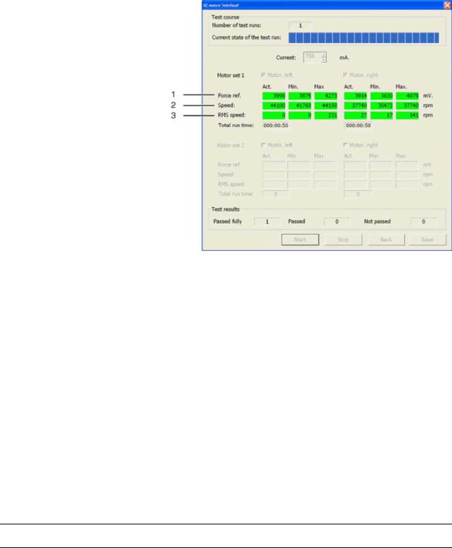
2.3.7 DC motors 'Load/inlet' |
Purpose of Test: |
This test serves to run in the DC motors and check them for proper functioning |
|
under continuous load. |
Procedure |
The DC motors are tested through operation at a constant current. The |
|
resulting speed provides an indication of the running resistance of the motor. |
|
Stepping motors 'Load/Run-in' |
|
|
|
|
1 |
Force reference value |
3 |
Measure of speed |
|
|
|
|
fluctuations |
|
2 |
Actual speed |
|
|
|
The two motors (left motor, right motor) can be selected together or |
|||
|
separately. The speed range of the DC motor can be tested selectively via the |
|||
|
adjustable motor current. If no motor is selected, the START button is not |
|||
|
active. Default: Both motors selected. |
|
|
|
Test run: |
The test runs in an endless loop until the "Stop" button is actuated. The |
|||
|
current measured values are displayed. A test run consists of one part "run |
|||
|
time" and one part "pause" for each motor. |
|
||
61 83 292 D 3439 |
27 |
D 3439.076.01.02.02 03.2008 |

2 Description of the service software |
Sirona Dental Systems GmbH |
Individual Test Points |
Service Manual CEREC / inLab MC XL |
|
|
|
2.3.8 DC motors 'Touch' |
Purpose of Test: |
This test is used to check the two DC motors for proper functioning in the Low- |
|
speed mode. |
Procedure |
The DC motors are tested by adjusting them to the touch speed (in the |
|
relevant directions of rotation). Then the relevant data are determined. |
DC motors 'Touch'
1Measure of speed fluctuation
2Pulse-width modulation
The possible motors can be selected either together or separately.
If no motor is selected, the "Start" button is not active. Default: Both motors selected.
28 |
61 83 292 D 3439 |
D 3439.076.01.02.02 03.2008 |
|
|
|
Sirona Dental Systems GmbH |
2 Description of the service software |
Service Manual CEREC / inLab MC XL |
Individual Test Points |
|
|
|
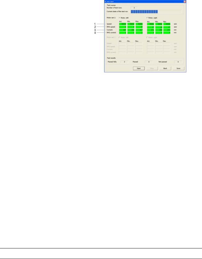
2.3.9 DC motors 'Speed' |
Purpose of Test: |
This test is used to check the two DC motors for proper functioning in the |
|
High-speed mode. |
|
DC motors 'Speed' |
|
|
|
|
1. |
Measured speed |
3. |
Measured motor current |
|
2. |
Fluctuation of speed |
4. |
Fluctuation of motor |
|
|
|
|
current |
Procedure |
The DC motors are tested by accelerating them from a standing start to |
|||
|
operating speed and then measuring the relevant data, e.g. speed and |
|||
|
current. |
|
|
|
61 83 292 D 3439 |
29 |
D 3439.076.01.02.02 03.2008 |

2 Description of the service software |
Sirona Dental Systems GmbH |
Individual Test Points |
Service Manual CEREC / inLab MC XL |
|
|
|
2.3.10Sensor test |
Purpose of Test: |
This test serves to evaluate the functioning and accuracy of the scanner. |
|
Sensor test |
|
|
|
|
1 |
Laser active signal level |
6 |
Measuring angle |
|
2 |
Laser inactive signal level |
7 |
Dimension of noise level |
|
3 |
Distance between scanner |
8 |
This test is deactivated in |
|
|
and measuring point |
|
the factory setting |
|
4 |
Focal size |
9 |
Scanner |
|
5 |
Selection of laser diode |
|
|
Procedure |
The various required measurements are performed with the help of the |
|||
|
calibration phantom. |
|
|
|
The functions to be tested can be selected in different variations. If no function is selected, the "Start" button is not active. Default setting: Test all functions.
30 |
61 83 292 D 3439 |
D 3439.076.01.02.02 03.2008 |
|
|
|
Loading...