


 Loading...
kÉï=~ë=çÑW= NMKOMMQ
pfsfpflk=OLP
pЙкобЕЙ=j~ем~д===== |
= |
|
|
|
|
|
bеЦдблЬ |
|
IMPORTANT:
•In case of faults which you are unable to eliminate with the help of this manual, please contact our Customer Service Center.
•It is essential that you take this Service Manual along with you on every customer call.
Furthermore, you must always have the spare parts list and wiring diagrams with you as well.
You can order additional copies of this Service Manual under the
•Order number 59 07 097 from our department DZL 1 in Bensheim.
See reverse side of manual for address.
59 07 097 D 3322.076.02.04.02 10.2004

kÉï=~ë=çÑW= |
NMKOMMQ |
pfsfpflk=OLP |
|
pЙкобЕЙ=j~ем~д==== |
|
|
bеЦдблЬ |

Contents
SIVISION 2/3

Contents
1 Important information ........................................................... |
1 – 1 |
|
1.1 |
Symbols ................................................................................. |
1 – 2 |
1.2 |
Abbreviations ......................................................................... |
1 – 3 |
1.3 |
Overview................................................................................ |
1 – 4 |
2 SIVISION 2 |
.............................................................................. |
2 – 1 |
2.1 |
General service aids .............................................................. |
2 – 2 |
2.2C2+ with SIROCAM 2 in the dentist element,
|
second monitor C2+ ............................................................... |
2 – 3 |
2.2.1 |
Overview of PCBs/modules .................................................. |
2 – 3 |
2.2.2 Dentist element with SIROCAM 2 ......................................... |
2 – 3 |
|
2.2.3 |
Patient chair .......................................................................... |
2 – 5 |
2.2.4 |
Monitor ................................................................................. |
2 – 6 |
2.2.5 Video application with PC interfacing ................................... |
2 – 7 |
|
2.2.6Block diagram of C2+
|
with SIVISION 2 SIROCAM 2 on C2+ ................................... |
2 – 8 |
2.2.7 Block diagram of C2+ |
|
|
|
with SIVISION 2 SIROCAM 2 with PC link to C2+ ................ |
2 – 8 |
2.3 |
ProFeel video application ...................................................... |
2 – 9 |
2.3.1 |
Overview of PCBs/modules .................................................. |
2 – 9 |
2.3.2 Compact box on the lamp support ........................................ |
2 – 9 |
|
2.3.3 |
Monitor ................................................................................. |
2 – 10 |
2.3.4 Compact box PC connection ................................................ |
2 – 10 |
|
2.3.5 Block diagrams ProFeel with SIVISION 2 ............................. |
2 – 11 |
|
3 SIVISION 3 |
.............................................................................. |
3 – 1 |
3.1 |
Function of the camera .......................................................... |
3 – 2 |
3.2 |
Video components ................................................................. |
3 – 3 |
3.3 |
General service aids .............................................................. |
3 – 3 |
3.3.1 Automatic signal source switchover ...................................... |
3 – 3 |
|
3.3.2 |
Signal source search ............................................................ |
3 – 4 |
3.3.3 Storage and still image ......................................................... |
3 – 4 |
|
3.3.4 |
White/black screen ............................................................... |
3 – 5 |
3.3.5 |
Image quality ........................................................................ |
3 – 5 |
3.3.6 |
Image failure ......................................................................... |
3 – 5 |
3.3.7 |
Optimum image resolution .................................................... |
3 – 6 |
3.4 |
C1+ with SIROCAM 2 in the dentist element ......................... |
3 – 7 |
3.4.1 |
Overview of PCBs/modules .................................................. |
3 – 7 |
3.4.2 Dentist element with SIROCAM 2 ......................................... |
3 – 7 |
|
3.4.3 |
Patient chair .......................................................................... |
3 – 8 |
3.4.4 |
Monitor .................................................................................. |
3 – 8 |
3.4.5 Block diagram of C1+ with Sivision |
|
|
|
SIROCAM 2 with PC connection to the C1+ ......................... |
3 – 9 |
II
59 07 097 D 3322 D 3322.076.02.04.02 10.2004

|
|
Contents |
|
|
|
3.5 |
C1+ with SIROCAM 3/C in the dentist element |
...................... 3 – 10 |
3.5.1 |
Overview of PCBs/modules .................................................. |
3 – 10 |
3.5.2 Dentist element with SIROCAM 3/C ..................................... |
3 – 10 |
|
3.5.3 |
Patient chair .......................................................................... |
3 – 11 |
3.5.4 |
Monitor ................................................................................. |
3 – 12 |
3.5.5Block diagram of C1+ with Sivision
|
SIROCAM 3/C with PC connection to the C1+ ..................... |
3 – 13 |
3.6 |
C2+ with SIROCAM 2 in the dentist element ......................... |
3 – 14 |
3.6.1 |
Overview of PCBs/modules .................................................. |
3 – 14 |
3.6.2 Dentist element with SIROCAM 2 ......................................... |
3 – 14 |
|
3.6.3 |
Patient chair .......................................................................... |
3 – 15 |
3.6.4 |
Monitor .................................................................................. |
3 – 15 |
3.6.5 Block diagram of C2+ with Sivision 3 |
|
|
|
SIROCAM 2 with PC connection to the C2+ ......................... |
3 – 16 |
3.7C2+, C4+, M1+ SN £ 69.999
|
with SIROCAM 3/C in the dentist element............................. |
3 – 17 |
3.7.1 |
Overview of PCBs/modules .................................................. |
3 – 17 |
3.7.2 |
Dentist element with SIROCAM 3/C ..................................... |
3 – 17 |
3.7.3 |
Patient chair ......................................................................... |
3 – 19 |
3.7.4 |
Monitor ................................................................................. |
3 – 20 |
3.7.5Block diagram of C2+,C4+ and M1+ with Sivision 3
SIROCAM 3/C with PC connection ....................................... |
3 – 20 |
3.8C2+, C4+, M1+ from SN 70.000
|
with SIROCAM 3/C in the dentist element............................. |
3 – 21 |
3.8.1 |
Overview of PCBs/modules .................................................. |
3 – 21 |
3.8.2 |
Dentist element with SIROCAM 3/C ...................................... |
3 – 21 |
3.8.3 |
Patient chair ......................................................................... |
3 – 23 |
3.8.4 |
Monitor ................................................................................. |
3 – 24 |
3.8.5Block diagram of C2+/C4+/M1+ with Sivision 3
|
SIROCAM 3/C with PC connection ....................................... |
3 – 24 |
3.9 |
C3+ with SIROCAM 3/C in the dentist element...................... |
3 – 25 |
3.9.1 |
Overview of PCBs/modules .................................................. |
3 – 25 |
3.9.2 Dentist element with SIROCAM 3/C ..................................... |
3 – 25 |
|
3.9.3 |
Patient chair ......................................................................... |
3 – 26 |
3.9.4 |
Monitor ................................................................................. |
3 – 27 |
3.9.5Block diagram of C3+ with Sivision 3 SIROCAM 3/C with PC connection to the C3+
|
Camera in the dentist element .............................................. |
3 – 28 |
3.10 |
C5+ with SIROCAM 3/C in the dentist element...................... |
3 – 29 |
3.10.1 |
Overview of PCBs/modules .................................................. |
3 – 29 |
3.10.2 Dentist element with SIROCAM 3/C ..................................... |
3 – 29 |
|
3.10.3 |
Patient chair ......................................................................... |
3 – 30 |
3.10.4 |
Monitor ................................................................................. |
3 – 31 |
3.10.5Block diagram of C5+ with Sivision 3 SIROCAM 3/C with PC connection to the C5+
Camera in the dentist element .............................................. |
3 – 32 |
bеЦдблЬ
59 07 097 D 3322
D 3322.076.02.04.02 10.2004
III

Contents
3.11C3+/C4+/C5+ with SIROCAM 3/C
|
in the assistant element (not for C5+ Turn) ........................... |
3 – 33 |
3.11.1 |
Overview of PCBs/modules .................................................. |
3 – 33 |
3.11.2 Assistant element with SIROCAM 3/C .................................. |
3 – 33 |
|
3.11.3 |
Patient chair ......................................................................... |
3 – 34 |
3.11.4 |
Monitor ................................................................................. |
3 – 35 |
3.11.5Block diagram of C3+/C4+/C5+
with Sivision 3 SIROCAM 3/C with PC connection and camera
on the assistant element ....................................................... |
3 – 36 |
3.12C6 with SIROCAM 3/C
|
in the dentist element............................................................. |
3 – 37 |
3.12.1 |
Overview of PCBs/modules .................................................. |
3 – 37 |
3.12.2 Dentist element with SIROCAM 3/C ..................................... |
3 – 37 |
|
3.12.3 |
Patient chair ......................................................................... |
3 – 38 |
3.12.4 |
Monitor ................................................................................. |
3 – 38 |
3.12.5Block diagram of C6 with Sivision 3
|
SIROCAM 3/C with PC connection to the C6 ....................... |
3 – 39 |
3.13 |
C8 with SIROCAM 3/C in the dentist element ....................... |
3 – 40 |
3.13.1 |
Overview of PCBs/modules .................................................. |
3 – 40 |
3.13.2 Dentist element with SIROCAM 3/C ..................................... |
3 – 40 |
|
3.13.3 |
Patient chair ......................................................................... |
3 – 41 |
3.13.4 |
Monitor ................................................................................. |
3 – 41 |
3.13.5Block diagram of C8 with Sivision 3
|
SIROCAM 3/C with PC connection to the C8 ....................... |
3 – 42 |
3.14 |
C8+ with SIROCAM 3/C in the dentist element...................... |
3 – 43 |
3.14.1 |
Overview of PCBs/modules .................................................. |
3 – 43 |
3.14.2 Dentist element with SIROCAM 3/C ..................................... |
3 – 43 |
|
3.14.3 |
Patient chair ......................................................................... |
3 – 44 |
3.14.4 |
Monitor ................................................................................. |
3 – 44 |
3.14.5 Block diagram of C8+ with Sivision 3 |
|
|
|
SIROCAM 3/C with PC connection to the C8+ ..................... |
3 – 45 |
3.15ProFeel with SIROCAM 3/C
|
in the dentist element............................................................. |
3 – 46 |
3.15.1 |
Overview of PCBs/modules .................................................. |
3 – 46 |
3.15.2 Dentist element with SIROCAM 3/C ..................................... |
3 – 46 |
|
3.15.3 |
Water unit ............................................................................. |
3 – 47 |
3.15.4 |
Monitor ................................................................................. |
3 – 47 |
3.15.5Block diagram of ProFeel with Sivision 3
|
SIROCAM 3/C with PC connection to the ProFeel ............... |
3 – 48 |
3.16 |
Kompakt with SIROCAM 3/C ................................................. |
3 – 49 |
3.16.1 |
Overview of PCBs/modules .................................................. |
3 – 49 |
3.16.2 Kompakt with SIROCAM 3/C ................................................ |
3 – 49 |
|
3.16.3 |
Patient chair/water unit ......................................................... |
3 – 50 |
3.16.4 |
Monitor ................................................................................. |
3 – 51 |
3.16.5Block diagram - Sivision 3 Kompakt (KA module) SIROCAM 3/C with PC connection Kompakt
with KA module ..................................................................... |
3 – 52 |
3.16.6Block diagram - Sivision 3 Kompakt SIROCAM 3/C with PC connection Kompakt
|
Without KA module ............................................................... |
3 – 53 |
3.17 |
Retrofitting the C1, C2, C3, C4 treatment centers ................. |
3 – 54 |
IV
59 07 097 D 3322 D 3322.076.02.04.02 10.2004

|
|
Contents |
|
|
|
4 PC connection ........................................................................ |
4 – 1 |
|
4.1 |
Product features of the PC connection .................................. |
4 – 2 |
4.2 |
Function description............................................................... |
4 – 2 |
4.2.1 |
PC block diagram ................................................................. |
4 – 3 |
4.2.2 |
Functional sequences ........................................................... |
4 – 3 |
4.3 |
Function description of individual components ...................... |
4 – 5 |
4.3.1 |
Treatment center/PC interfaces ............................................ |
4 – 5 |
4.3.2 |
Hardware and drivers ........................................................... |
4 – 5 |
4.3.3 |
PC application programs ...................................................... |
4 – 9 |
4.4 |
Service information ................................................................ |
4 – 12 |
4.4.1 |
Installation ............................................................................. |
4 – 12 |
4.4.2 |
Known errors and limitations ................................................ |
4 – 13 |
4.4.3 |
Hints for troubleshooting ....................................................... |
4 – 13 |
bеЦдблЬ
59 07 097 D 3322
D 3322.076.02.04.02 10.2004
V
1 Important information
Important information
1.1Symbols
C1+ dentist element
C1+
C2+ dentist element
C2+
C3+ dentist element
C3+
C4+ dentist element
C4+
C5+ dentist element
C5+
M1+ dentist element
M1+
C6 dentist element
C6 
C8, C8+ dentist element
C8
ProFeel dentist element
Assistant element
Patient chair
ProFeel patient chair
1 – 2 |
59 07 097 D 3322 |
D 3322.076.02.04.02 10.2004 |
|
|
|
Water unit
ProFeel water unit
Kompakt
Monitor
PC connection
Important information
bеЦдблЬ
1.2 |
Abbreviations |
|
|
|
|
|
AE |
Dentist element |
|
|
|
|
AK |
Connection box |
|
|
|
|
AP |
Dentist panel |
|
COM |
Serial interface |
|
|
|
|
PCB |
Printed circuit board |
|
|
|
|
FS |
Pedal (foot switch) |
|
|
|
|
FT |
Foot button |
|
|
|
|
GND |
Ground |
|
|
|
|
HE |
Assistant element |
|
HP |
Assistant element control |
|
|
|
|
HW |
Hardware |
|
|
|
|
KB |
Analog camera PCB |
|
|
|
|
KL |
Holder |
|
|
|
|
L |
Cable |
|
|
|
|
LCD |
Liquid Crystal Display |
|
LED |
Light Emitting Diode |
|
|
|
|
MO |
Monitor |
|
|
|
|
PC |
Personal Computer |
|
|
|
|
RGB |
Electrical transmission possibility for video images, i.e. image |
|
|
signal split according to the basic TV colors of red, green and |
|
|
blue. |
|
|
|
|
SDI |
Sirona Dental Interface (electrical, pneumatic, hydraulic plug |
|
|
connection) |
|
|
|
59 07 097 D 3322 |
1 – 3 |
|
D 3322.076.02.04.02 10.2004 |
||
|
|
|

Important information
ST |
Patient chair |
|
|
S video |
This is an image signal split into color and brightness. Com- |
|
pared to composite video information, which is sent through a |
|
single line, this signal transmission facilitates images with less |
|
noise and higher definition. S video images have almost the |
|
same image quality as RGB images. The color depth is 16 mil- |
|
lion colors (True Color). |
|
|
SW |
Software |
|
|
VGA |
In this Service Manual, the RGB connection between PC and |
|
treatment center monitor is designated as VGA. It does not rep- |
|
resent the resolution of the image signal. Sirona also uses the |
|
designation XGA instead of VGA frequently, e.g. XGA cable. |
|
|
TR |
Support arm |
|
|
VAC |
AC voltage |
|
|
VDC |
DC voltage |
WE |
Water unit |
|
|
X |
Connector |
|
|
+Viso |
Galvanically isolated voltage |
1.3Overview
For the sake of completeness, Sivision 1 applications are also described in the table, provided they are installed in C Line and ProFeel systems.
The serial numbers (SNs) refer to the SNs of the dental units.
Overview of SIVISION 2/SIVISION 3/second monitor
|
Treatment center version |
Version |
|
PC connection |
|
||||
Device |
Camera |
Version |
Camera |
Sivision 1/2/3 or |
Siucom unit |
COM port |
S video |
VGA connection |
|
designation |
location |
second monitor |
selection |
(RS-232 cable) |
connection |
||||
|
|
|
|||||||
C1-96a |
SIROCAM 3/C |
|
Dentist element |
S3 |
C1 |
SVC PCB |
SVC PCB |
SVC retaining plate |
|
C1-96b |
SIROCAM 2 |
|
Dentist element |
S3 |
C1 |
SVC PCB |
SVC PCB |
SVC retaining plate |
|
C1-96a |
SIROCAM 3/C |
Kompakt |
Monitor |
S3 |
SIROCAM 3/C |
KA retaining plate |
KA PCB |
KA retaining plate |
|
|
|
|
|
|
direct |
|
|
|
|
C1-96b |
SIROCAM 2 |
SIVISION 1 |
Monitor |
S1 |
SIROCAM Box |
AK interface |
AK interface |
AK interface |
|
|
|
|
|
|
|
|
|
|
|
C1+a |
SIROCAM 3/C |
|
Dentist element |
S3 |
C1 |
SVC PCB |
SVC PCB |
SVC retaining plate |
|
C1+b |
SIROCAM 2 |
|
Dentist element |
S3 |
C1 |
SVC PCB |
SVC PCB |
SVC retaining plate |
|
C1+a |
SIROCAM 3/C |
Kompakt |
Monitor |
S3 |
SIROCAM 3/C |
KA retaining plate |
KA PCB |
KA retaining plate |
|
|
|
|
|
|
direct |
|
|
|
|
C1+b |
without |
Second monitor |
--- |
sm |
C1 |
SVC PCB |
--- |
SVC retaining plate |
|
|
|
|
|
|
|
|
|
|
|
C2 |
SIROCAM 2 |
SIVISION 1 |
Monitor |
S1 |
SIROCAM Box |
AK interface |
AK interface |
AK interface |
|
|
|
|
|
|
|
|
|
|
|
|
SIROCAM 3/C |
Kompakt |
Monitor |
S3 |
SIROCAM 3/C |
KA retaining plate |
KA PCB |
KA retaining plate |
|
|
|
|
|
|
direct |
|
|
|
|
|
|
|
|
|
|
|
|
|
|
C2+, |
|
|
|
|
|
|
On retain. plate |
On retain. plate |
|
SN ≤ |
SIROCAM 2 |
|
Dentist element |
S2 |
C2 |
CJ PCB |
above 12 V |
above 12 V power |
|
69.000 |
|
|
|
|
|
|
power supply |
supply |
|
|
|
|
|
|
|
|
|
|
|
|
SIROCAM 2 |
|
Dentist element |
S3 |
C2 |
CJ PCB |
SVI PCB |
|
|
|
|
|
|
1 – 4 |
59 07 097 D 3322 |
D 3322.076.02.04.02 10.2004 |
|
|
|

Important information
Overview of SIVISION 2/SIVISION 3/second monitor |
|
|
|
|
|
|
||||
|
|
|
|
|
|
|
|
|
|
|
|
Treatment center version |
Version |
|
PC connection |
|
|
|
|||
Device |
Camera |
Version |
Camera |
Sivision 1/2/3 or |
Siucom unit |
COM port |
S video |
VGA connection |
|
bеЦдблЬ |
designation |
location |
second monitor |
selection |
(RS-232 cable) |
connection |
|
||||
|
|
|||||||||
|
|
|
|
|
||||||
C2+, |
|
|
|
|
|
SN ≤ 69.999 |
SN ≤ 69.999 |
SN ≤ 69.999 |
|
|
M1+ |
SIROCAM 3/C |
|
Dentist element |
S3 |
C1 |
SVI board |
SVI board |
SVI retaining plate |
|
|
|
|
SN ≥ 70.000 |
SN ≥ 70.000 |
SN ≥ 70.000 |
|
|
||||
|
|
|
|
|
|
|
|
|||
|
|
|
|
|
|
SVC board |
SVC board |
SVC retaining plate |
|
|
|
|
|
|
|
|
|
|
|
|
|
|
SIROCAM 3/C |
Kompakt |
Monitor |
S3 |
SIROCAM 3/C |
KA retaining plate |
KA PCB |
KA retaining plate |
|
|
|
|
|
|
|
direct |
|
|
|
|
|
|
|
|
|
|
|
|
|
On retain. plate |
|
|
|
without |
Second monitor |
--- |
sm |
C2 |
CJ PCB |
--- |
above 12 V power |
|
|
|
|
|
|
|
|
|
|
supply |
|
|
|
|
|
|
|
|
|
|
|
|
|
|
|
|
|
|
|
|
|
|
|
|
C3 |
SIROCAM 2 |
Sivision 1 |
Monitor |
S1 |
SIROCAM Box |
AK interface |
AK interface |
AK interface |
|
|
|
|
|
|
|
|
|
|
|
|
|
|
SIROCAM 3/C |
Kompakt |
Monitor |
S3 |
SIROCAM 3/C |
KA retaining plate |
KA PCB |
KA retaining plate |
|
|
|
|
|
|
|
direct |
|
|
|
|
|
|
|
|
|
|
|
|
|
|
|
|
C3+ |
|
|
|
|
|
|
SN ≤ 69.999 |
SN ≤ 69.999 |
|
|
|
SIROCAM 3/C |
|
Dentist element |
S3 |
C3 |
CJ PCB |
SVI board |
SVI retaining plate |
|
|
|
|
SN ≥ 70.000 |
SN ≥ 70.000 |
|
|
|||||
|
|
|
|
|
|
|
|
|
||
|
|
|
|
|
|
|
SVC board |
SVC retaining plate |
|
|
|
|
|
|
|
|
|
|
|
|
|
|
SIROCAM 3/C |
Kompakt |
Monitor |
S3 |
SIROCAM 3/C |
KA retaining plate |
KA PCB |
KA retaining plate |
|
|
|
|
|
|
|
direct |
|
|
|
|
|
|
|
|
|
|
|
|
SN ≤ 69.999 |
SN ≤ 69.999 |
|
|
|
SIROCAM 3/C |
|
Assistant |
S3 |
SIROCAM 3/C |
SVI PCB |
SVI board |
SVI retaining plate |
|
|
|
|
element |
direct |
SN ≥ 70.000 |
SN ≥ 70.000 |
|
|
|||
|
|
|
|
|
|
|
||||
|
|
|
|
|
|
|
SVC board |
SVC retaining plate |
|
|
|
|
|
|
|
|
|
|
|
|
|
|
|
|
|
|
|
|
|
On retain. plate |
|
|
|
without |
Second monitor |
--- |
sm |
C3 |
CJ PCB |
--- |
above 12 V power |
|
|
|
|
|
|
|
|
|
|
supply |
|
|
|
|
|
|
|
|
|
|
|
|
|
|
|
|
|
|
|
|
|
|
|
|
C4 |
SIROCAM 2 |
Sivision 1 |
Monitor |
S1 |
SIROCAM Box |
AK interface |
AK interface |
AK interface |
|
|
|
|
|
|
|
|
|
|
|
|
|
|
SIROCAM 3/C |
Kompakt |
Monitor |
S3 |
SIROCAM 3/C |
KA retaining plate |
KA PCB |
KA retaining plate |
|
|
|
|
|
|
|
direct |
|
|
|
|
|
|
|
|
|
|
|
|
|
|
|
|
C4+ |
|
|
|
|
|
|
SN ≤ 69.999 |
SN ≤ 69.999 |
|
|
|
SIROCAM 3/C |
|
Dentist element |
S3 |
C4 |
CJ PCB |
SVI board |
SVI retaining plate |
|
|
|
|
SN ≥ 70.000 |
SN ≥ 70.000 |
|
|
|||||
|
|
|
|
|
|
|
|
|
||
|
|
|
|
|
|
|
SVC board |
SVC retaining plate |
|
|
|
|
|
|
|
|
|
|
|
|
|
|
SIROCAM 3/C |
Kompakt |
Monitor |
S3 |
SIROCAM 3/C |
KA retaining plate |
KA PCB |
KA retaining plate |
|
|
|
|
|
|
|
direct |
|
|
|
|
|
|
|
|
|
|
|
|
SN ≤ 69.999 |
SN ≤ 69.999 |
|
|
|
SIROCAM 3/C |
|
Assistant |
S3 |
SIROCAM 3/C |
SVI PCB |
SVI board |
SVI retaining plate |
|
|
|
|
element |
direct |
SN ≥ 70.000 |
SN ≥ 70.000 |
|
|
|||
|
|
|
|
|
|
|
||||
|
|
|
|
|
|
|
SVC board |
SVC retaining plate |
|
|
|
|
|
|
|
|
|
|
|
|
|
|
|
|
|
|
|
|
|
On retain. plate |
|
|
|
without |
Second monitor |
--- |
sm |
C4 |
CJ PCB |
--- |
above 12 V power |
|
|
|
|
|
|
|
|
|
|
supply |
|
|
|
|
|
|
|
|
|
|
|
|
|
|
|
|
|
|
|
|
|
|
|
|
C5+ |
SIROCAM 3/C |
|
Dentist element |
S3 |
C4 |
CJ PCB |
KA PCB |
KA retaining plate |
|
|
|
SIROCAM 3/C |
Kompakt |
Monitor |
S3 |
SIROCAM 3/C |
KA retaining plate |
KA PCB |
KA retaining plate |
|
|
|
|
|
|
|
direct |
|
|
|
|
|
|
|
|
|
|
|
SN ≤ 69.999 |
SN ≤ 69.999 |
SN ≤ 69.999 |
|
|
|
SIROCAM 3/C |
|
Assistant |
S3 |
SIROCAM 3/C |
SVI board |
SVI board |
SVI retaining plate |
|
|
|
|
element |
direct |
SN ≥ 70.000 |
SN ≥ 70.000 |
SN ≥ 70.000 |
|
|
||
|
|
|
|
|
|
|||||
|
|
|
|
|
|
SVC board |
SVC board |
SVC retaining plate |
|
|
|
|
|
|
|
|
|
|
|
|
|
|
|
|
|
|
|
|
|
On retain. plate |
|
|
|
without |
Second monitor |
--- |
sm |
C4 |
CJ PCB |
--- |
above 12 V power |
|
|
|
|
|
|
|
|
|
|
supply |
|
|
|
|
|
|
|
|
|
|
|
|
|
|
|
|
|
|
|
|
|
|
|
|
59 07 097 D 3322 |
1 – 5 |
D 3322.076.02.04.02 10.2004 |

Important information
Overview of SIVISION 2/SIVISION 3/second monitor
Treatment center version |
Version |
|
PC connection |
|
||||
Device Camera |
Version |
Camera |
Sivision 1/2/3 or |
Siucom unit |
COM port |
S video |
VGA connection |
|
designation |
location |
second monitor |
selection |
(RS-232 cable) |
connection |
|||
|
|
|||||||
|
|
|
|
|
|
|
|
|
C6, C8, |
SIROCAM 3/C |
|
Dentist element |
S3 |
SIROCAM 3/C |
SVI PCB |
SVI PCB |
SVI retaining plate |
C8+ |
|
direct |
||||||
|
|
|
|
|
|
|
||
|
SIROCAM 3/C |
Kompakt |
Monitor |
S3 |
SIROCAM 3/C |
KA retaining plate |
KA PCB |
KA retaining plate |
|
|
|
|
|
direct |
|
|
|
|
|
|
|
|
PC control |
|
|
On retain. plate |
|
without |
Second monitor |
--- |
sm |
--- |
--- |
above 12 V power |
|
|
not possible |
|||||||
|
|
|
|
|
|
|
supply |
|
|
|
|
|
|
|
|
|
|
|
|
|
|
|
|
|
|
|
|
|
|
|
|
|
|
|
|
ProFeel |
SIROCAM 2 |
Video |
Monitor |
S1 |
SIROCAM Box |
SIROCAM Box |
SIROCAM Box |
Monitor |
|
applicationc |
|||||||
|
|
|
|
|
|
|
|
|
|
SIROCAM 3/C |
|
Dentist element |
S3 |
SIROCAM 3/C |
SVI PCB |
SVI PCB |
|
|
|
direct |
|
|||||
|
|
|
|
|
|
|
|
|
|
|
|
|
|
|
|
|
|
|
SIROCAM 3/C |
Kompakt |
Monitor |
S3 |
SIROCAM 3/C |
KA retaining plate |
KA PCB |
SVI retaining plate |
|
|
|
|
|
direct |
|
|
|
|
|
|
|
|
PC control |
|
|
On retain. plate |
|
without |
Second monitor |
--- |
sm |
--- |
--- |
above 12 V power |
|
|
not possible |
|||||||
|
|
|
|
|
|
|
supply |
|
|
|
|
|
|
|
|
|
|
|
|
|
|
|
|
|
|
|
|
|
|
|
|
|
|
|
|
SIRO- |
|
|
|
|
|
|
|
|
CAM |
SIROCAM 2 |
SIROCAM Box |
SIROCAM Box |
S1 |
SIROCAM Box |
SIROCAM Box |
SIROCAM Box |
Monitor |
Box |
|
|
|
|
|
|
|
|
|
|
|
|
|
|
|
|
|
|
|
|
|
|
|
|
|
|
aSoftware prerequisites: AK Version 3.2 or higher HP Version 2.5 or higher AJ Version 2.9 or higher
bSoftware prerequisites: AK Version 3.0 or higher AP Version 2.3 or higher AJ Version 2.5 or higher
cFormer ProFeel video application (delivery up to 4/2001)
The connections for SIROCAM C and SIROCAM 3 are identical.
1 – 6 |
59 07 097 D 3322 |
D 3322.076.02.04.02 10.2004 |
|
|
|

2 SIVISION 2
C2+
ProFeel

SIVISION 2
|
2.1 General service aids |
Image quality/image failure |
In case of poor image quality, the “Auto Setting” function of the monitor |
|
can bring about an improvement. |
|
A reduction of the PC graphics card “Refresh rate” setting to 60 Hz can al- |
|
so bring about an improvement in image quality. After display parameters |
|
on the PC graphics card have been changed, the “Auto Setting” function |
|
of the monitor should be activated once again. |
|
If no image appears on the monitor, you can connect the plug of the VGA |
|
cable of the treatment center located in the junction box to the VGA output |
|
of a notebook for test purposes. |
|
A second possibility of ruling out a possible cable problem is to replace the |
|
VGA cable run in the treatment center by a standard VGA cable between |
|
the PC/notebook and the monitor. |
2 – 2 |
59 07 097 D 3322 |
D 3322.076.02.04.02 10.2004 |
|
|
|
SIVISION 2
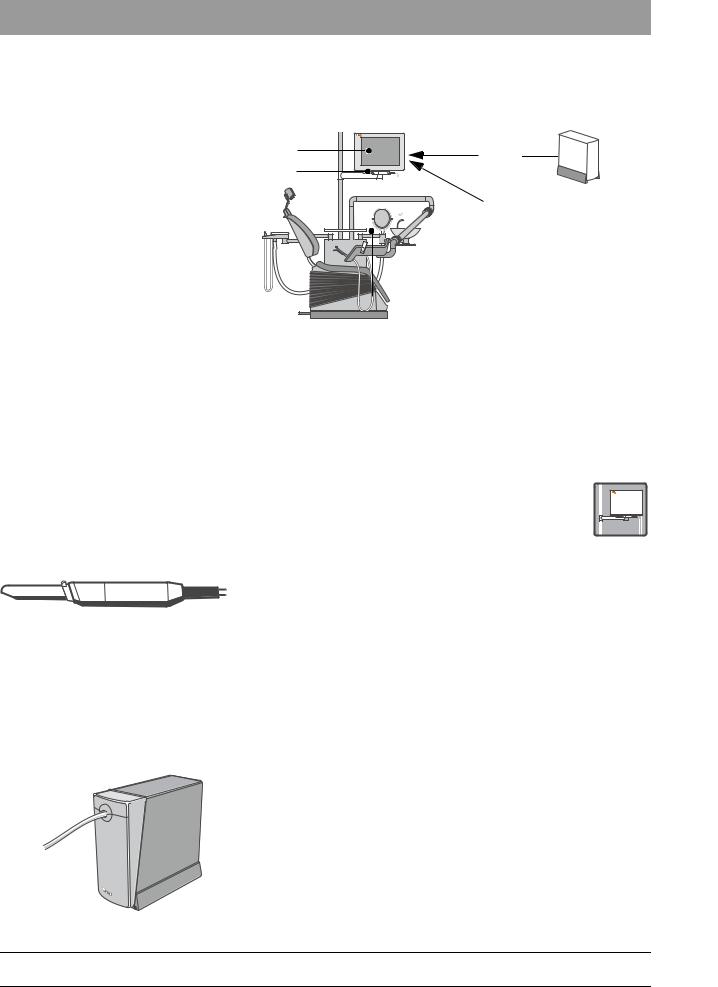
2.2C2+ with SIROCAM 2 in the dentist element, second monitor C2+
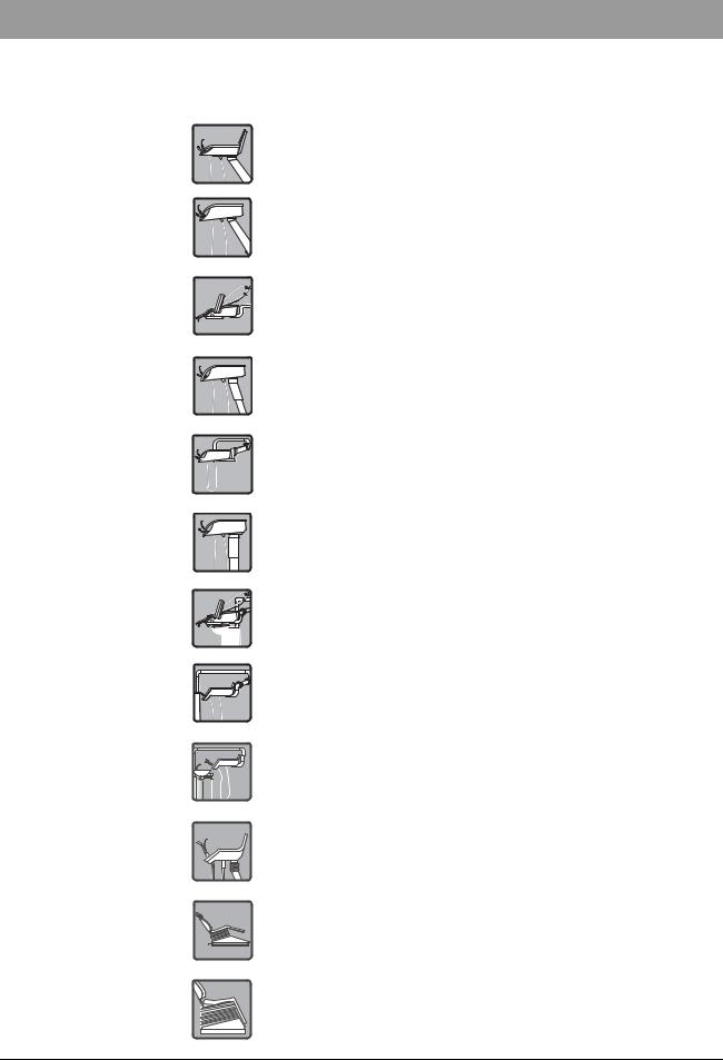
2.2.1 Overview of PCBs/modules
bеЦдблЬ
MO AE ST
Component |
PCB/module |
|
Dentist element (AE) |
ADX |
= Unit electronics |
|
AKV |
= Interface between camera unit and |
|
|
unit electronics |
|
|
|
|
KB |
= Camera PCB |
|
SC2 |
= SIROCAM 2 |
|
|
|
Patient chair (ST) |
CJ |
= Chair PCB |
|
NM |
= Monitor power supply |
|
|
|
|
VGA |
= Video converter |
Monitor (MO) |
|
|
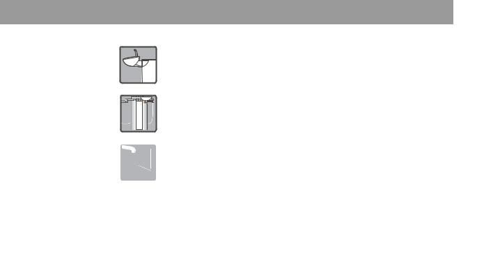
2.2.2 Dentist element with SIROCAM 2
|
|
The SIROCAM 2 is characterized by a high-quality optical sys- |
|
|
|
tem. The lighting is located in the dentist element and is run |
C2+ |
|
|
through a fiber-optic cable to the camera head. |
|
SIROCAM |
|
The Sirocam 2 is intended for the smile line range close to the teeth as well |
|
|
|
as for the full face range. The distance adjustment is continuously variable. |
|
|
|
||
The housing is made of titanium and the lens protective sleeve can be removed and sterilized. The image memory is not located in the camera, but on the VGA converter PCB.
To compensate for camera-specific influences on the color settings, data for the analog camera PCB KB is stored in the camera head.
59 07 097 D 3322 |
2 – 3 |
D 3322.076.02.04.02 10.2004 |
SIVISION 2
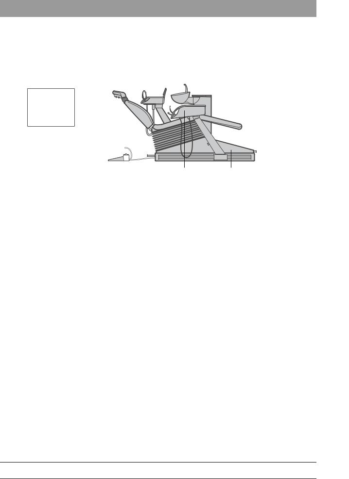
Dentist element control ADX
ADX
Camera PCB KB
KB
LED
The unit electronics (PCB ADX) detects the presence of the optional camera system in the dentist element from an identifier resistor on PCB AKV. In this case, the camera is treated by the unit electronics in the same way as an instrument.
When removal of the camera is detected by the photoelectric light barrier at the holder, information about the active video system appears on the LCD panel, and the software allows switching between live image, white screen and still image (freeze) by means of the foot switch (or keyboard).
All the other instruments of the dentist element – apart from the Sprayvit – are blocked. If the camera is removed after an instrument has already been removed, it switches directly to live image mode; switching by means of the foot switch is then no longer possible.
The video signal of the camera is processed to form a standard signal (S video) on PCB KB.
A red LED indicating the status of the communication to the camera head is located on PCB KB:
LED off |
Camera OK |
LED flashes |
Camera head does not respond |
|
|
LED on |
Camera not working correctly or defective |
|
|
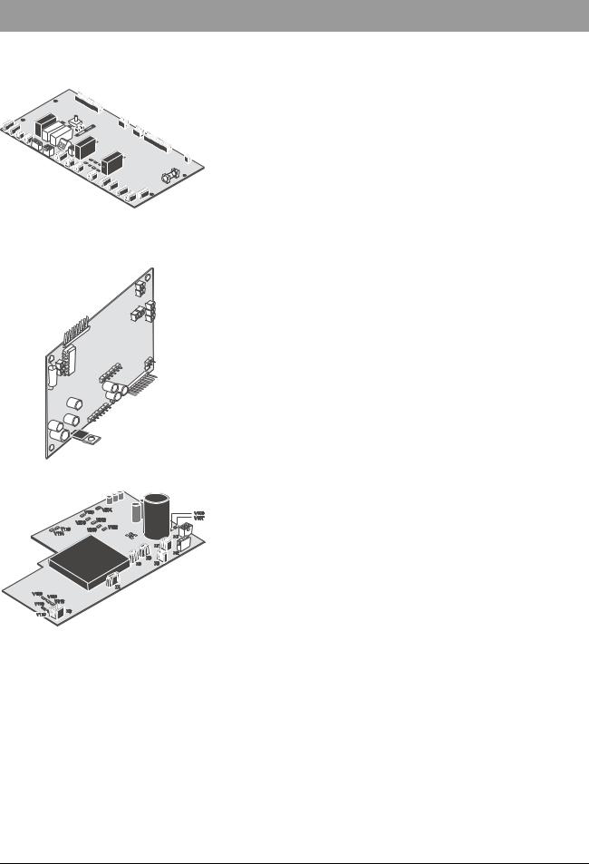
PCB AKV |
The interface between the camera unit and the unit electronics is PCB AKV, |
|
on which the galvanic isolation between patient circuit and the operating and/ |
|
or control voltages of the camera system is implemented. The camera/video |
|
functions are contacted to protective ground. |
AKV
Functional units on PCB AKV |
Switched-mode power supply for halogen lamp and fan: |
The 16VAC from the transformer in the junction box are rectified on PCB AKV and converted into a supply voltage of approx. 11.5VDC for the fan and the halogen lamp.
This switched-mode power supply is activated by a control signal from the logic unit of the AKV.
Power supply for the camera and its electronics with galvanic isolation:
A DC/DC converter with galvanic isolation converts the rectified input voltage of PCB AKV into a supply voltage of approx. 12VDC for the camera and the camera electronics. This converter is activated by a control signal from the logic unit of the AKV.
2 – 4 |
59 07 097 D 3322 |
D 3322.076.02.04.02 10.2004 |
|
|
|
SIVISION 2
|
Processing of control signals/status signal of the unit electronics/ |
|
camera with galvanic isolation: |
|
The corresponding control and status signals between the unit electronics |
|
and the camera electronics are galvanically isolated from each other by |
|
optocouplers. |
|
These signals are supplied to a logic unit, which for instance generates |
|
the run-on time of the fan, enabling of the above power supplies for halo- |
|
gen lamp and camera electronics, as well as safety shutdown of the halo- |
|
gen lamp on overtemperature in the lamp box. |
|
Power supply for the logic unit: |
|
With the help of voltage regulators, the necessary supply voltages are |
|
generated for the two galvanically isolated logic units (+5 V and +5 Viso). |
Description of the basic functions on |
When the supply voltage is applied, the green LEDs V107 (+5 V) and |
PCB AKV: |
V106 (+20 V) light up. |
|
The unit electronics (PCB ADX) sends a control signal to PCB AKV when |
|
the camera is removed and active (yellow LED V118 (CamIn) is on), and |
|
the power supply for the camera and its electronics is enabled |
|
(green LEDs V110 (+12 Viso) and V113 (+5 Viso) are on). |
|
When the camera is plugged in, the camera electronics send a “Camera |
|
OK” status signal back to PCB AKV (yellow LED V114 (StatusOut) is on), |
|
through which the switched-mode power supply for the halogen lamp and |
|
the fan is activated (green LED V304 (Lamp+) is on). |
|
With an active temperature sensor (overtemperature case, LED V200 |
|
(Temp. sens) is on), the halogen lamp is turned off, but the camera and fan |
|
functions remain as they are. |
|
When the camera unit is deactivated by the unit electronics, the fan con- |
|
tinues running for a short time. |
|
The two control signals Control_1 and Control_2 are currently not used. |
|
2.2.3 Patient chair |
|
The video converter has the task of converting an S video signal |
|
into a VGA signal. |
VGA video converter |
The image memory function (switching between still/live image) as well as |
|
the white screen function are controlled through the control inputs on connec- |
|
tor X2. If an S video signal is no longer present in live image mode, then the |
|
system switches to a black screen. |
|
With a PC connection, the VGA converter is not required! The white screen is |
|
generated by the PC. |
bеЦдблЬ
59 07 097 D 3322 |
2 – 5 |
D 3322.076.02.04.02 10.2004 |

SIVISION 2
Power supply unit
CJ, chair PCB
CJ
PC connection
The 12VDC output voltage of the power supply unit is required for the monitor and the VGA converter module.
The white screen control as well as switching between still/live image of the converter is performed by PCB CJ (X80).
With a PC connection/second monitor, PCB CJ conducts the function key commands through the RS232 interface (X11) to the PC. The RS232 commands are structured according to the Mouse Systems Protocol, whereby only the first byte is used. Both the control outputs (X80) and the RS232 interface (X11) are galvanically isolated, so that they can be connected directly with the PC or converter.
The transmission parameters are: 9600 baud, 8 data bits, no parity, 1 stop bit. No protocol.
PC connection of the video application/second monitor
The VGA cable of the PC is connected with the VGA cable of the monitor and fastened with a retaining clamp on the retaining plate of the monitor power supply unit.
The RS232 connection is plugged into PCB CJ at position X11. (Check for proper fit, especially after service work in the area of the junction box)
The grounding cable of the PC is fastened to the proposed grounding point.
For PC connection of the video application only:
The S video cable of the PC is connected with the S video cable of the video application and fastened to the retaining plate (make sure there is correct contact with the metal parts of the connector).
2.2.4 Monitor
The monitor has two VGA inputs; VGA input A should be preferred.
The 12VDC power supply is made through the 4-pin POWER MINI DIN plug.
Refer to the operating instructions for operation of the monitor. The LED next to the on/off switch can assume three states:
|
green |
there is a VGA signal present |
|
orange |
there is no VGA signal present |
|
|
|
|
off |
monitor is switched off or no voltage available |
|
|
|
2 – 6 |
59 07 097 D 3322 |
|
D 3322.076.02.04.02 10.2004 |
||
|
|
|

SIVISION 2
2.2.5 Video application with PC interfacing
The camera S video signal as well as the control signals generated by the treatment center are sent to the external PC for further processing.
The analog S video signal is digitized on the frame grabber card of the PC and then converted on the graphics card of the PC into an analog VGA signal for display on the treatment center monitor.
When the camera is removed from the dentist element, a live image is transmitted via the S video cable and a removal signal is sent to the PC via the RS232. A window with the live image is automatically opened by the removal signal in the Sidexis/Videxis software.
When the camera is deposited, a control signal sent by the treatment center closes the window with the camera image, and the video signal is switched off.
Further control signals sent from the treatment center to the PC via the RS232 are used for:
switching over between the live and the still image (by means of the foot switch)
saving the still image
switching to white/black screen (white and black screen are generated by the PC)
as well as further freely configurable PC control functions
bеЦдблЬ
59 07 097 D 3322 |
2 – 7 |
D 3322.076.02.04.02 10.2004 |
SIVISION 2
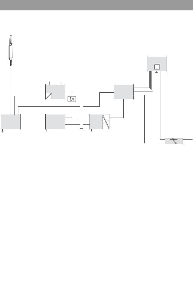
2.2.6Block diagram of C2+ with SIVISION 2 SIROCAM 2 on C2+
Camera in light barrier holder
(Removal detection: ADX)
Flange |
|
Lamp |
|
|
Fan |
|
Temp. sensor |
|||
|
|
|
|
|
|
|
|
|
|
|
|
|
Control signal |
|
|
PCB |
|
VGA |
||
|
|
|
||
AKV |
|
|
S video |
converter |
12V
|
S video |
|
|
|
|
Camera module |
Unit control |
16VAC |
connector |
PCB |
Control signal |
|
|
|
SDI |
CJ |
RS232 |
|
|
CAN |
|
||
PCB |
PCB |
CAN |
|
||
|
|
V24 |
|
||
KB |
ADX |
|
|
1.5kV |
|
|
|
|
Monitor
LC display
|
12VDC |
|
12VDC |
4kV |
Network |
|
NM |
|
2.2.7Block diagram of C2+ with SIVISION 2 SIROCAM 2 with PC link to C2+
Camera in light barrier holder
(Removal detection: ADX)
Flange |
Lamp |
Fan |
Temp. sensor |
|
||
|
|
PCB |
Control signal |
|
|
|
|
|
|
|
|
|
|
|
|
AKV |
|
|
|
|
12V |
|
|
|
|
|
|
|
|
S video |
|
|
|
|
Camera module |
|
Unit control |
16VAC |
connector |
PCB |
|
|
|
|
|
SDI |
CJ |
RS232 |
|
|
|
CAN |
|
||
PCB |
|
PCB |
CAN |
|
||
|
|
|
V24 |
|
||
KB |
|
ADX |
|
|
1.5kV |
|
|
|
|
|
|||
With a PC connection, the VGA converter is not required!
Monitor |
|
Monitor |
||||
LC display |
|
|
PC |
|||
|
|
|
|
|
|
|
|
|
|
|
|
|
|
|
|
VGA |
|
VGA |
|
|
Graphics card |
|
|
S video |
|
|
Frame grabber |
|
|
RS232 |
PC |
|
IO |
|
|
12VDC |
|
12VDC |
4kV |
Network |
|
NM |
|
2 – 8 |
59 07 097 D 3322 |
D 3322.076.02.04.02 10.2004 |
|
|
|
SIVISION 2
2.3ProFeel video application
2.3.1 Overview of PCBs/modules
|
SIVISION |
MO |
SCB |
|
|
SC2 |
|
|
NM |
|
VGA |
Component |
PCB/module |
|
Lamp support tube |
MO |
= Monitor |
|
|
|
|
NM |
= Monitor power supply |
|
SIROCAM 2 |
|
|
|
|
|
SCB |
= Sirocam 2 box |
|
VGA |
= VGA converter |
|
|
|
|
|
|
2.3.2 Compact box on the lamp support |
|
|
|
|
|
|
|
|
|
|
|
|
|
|
||||||||
|
|
|
The SIVISION 2 on the ProFeel is a compact camera solution on |
|
|
|
|
|
|
|
|
|
|
|
|
|
|
|
|
|
|
|
|
|
|
|
|
|
|
|
|
|
|
|
|
|
|
|
|
|
|
the lamp support tube, consisting of screen, camera, |
|
|
|
|
|
|
|
|
|
|
|
|
|
|
|
|
|
|
|
|
|
|
SIROCAM 2 |
SIROCAM 2 box, converter and power supply unit. |
|
|
|
|
|
|
|
|
|
||
The SIROCAM 2 is characterized by a high-quality optical system. The light- |
||||||||||||
|
|
|
ing is located in the dentist element and is guided through a fiber-optic cable |
|||||||||
|
|
|
to the camera head. |
|||||||||
|
|
|
||||||||||
|
|
|
It is intended for the range close to the teeth plus smile line. The distance |
|||||||||
|
|
|
adjustment is continuously variable. |
|||||||||
|
|
|
The housing is made of titanium. The lens protective sleeve can be removed |
|||||||||
|
|
|
and sterilized. The image memory is not located in the camera, but on the |
|||||||||
|
|
|
VGA converter PCB. |
|||||||||
|
|
|
A reed contact integrated in the camera enables operation by the holder |
|||||||||
|
|
|
installed on the monitor. This means that the camera is switched on or off by |
|||||||||
|
|
|
means of a magnet in the holder. |
|||||||||
SIROCAM 2 box |
The SIROCAM 2 box is the basis of the SIVISION 2 video solution on the |
|||||||||||
|
|
|
ProFeel (refer also to the SIROCAM 2 Service Manual, Part No.: 58 24 045). |
|||||||||
bеЦдблЬ
2
M
A
C
O
R
I
S
59 07 097 D 3322 |
2 – 9 |
D 3322.076.02.04.02 10.2004 |

SIVISION 2
VGA video converter |
The video converter has the task of converting an S video signal into a VGA |
|
signal. |
The image memory function (switching between still/live image) as well as the white screen function are controlled through the control inputs on connector X2. If an S video signal is no longer present in live image mode, then the system switches to a black screen. The necessary control signals are fed directly to the converter input X2 by a rocker switch on the chair panel.
With a PC connection, the VGA converter is not required! The white screen is generated by the PC.
Power supply unit |
The 12VDC output voltage of the power supply unit is required for the monitor, |
|
the VGA converter module and the fan. |
2.3.3 Monitor
The monitor has two VGA inputs; VGA input A should be preferred.
The 12VDC power supply is made through the 4-pin POWER
MINI DIN plug. Refer to the operating instructions for operation of the monitor.
The LED next to the on/off switch can assume three states:
green |
there is a VGA signal present |
orange |
there is no VGA signal present |
|
|
off |
monitor is switched off or no voltage available |
|
|
|
2.3.4 Compact box PC connection |
PC connection |
PC connection of the video application/second |
|
monitor |
|
The 4 cables required for the PC connection are run directly from |
|
the SIROCAM box (S video and RS232), from the monitor (VGA) |
|
and from the grounding point (protective ground wire) through the support |
|
arm and the water unit up to the PC. |
|
In the case of the PC connection of the second monitor, the S video & RS232 |
|
cables are not present. |
2 – 10 |
59 07 097 D 3322 |
D 3322.076.02.04.02 10.2004 |
|
|
|
SIVISION 2
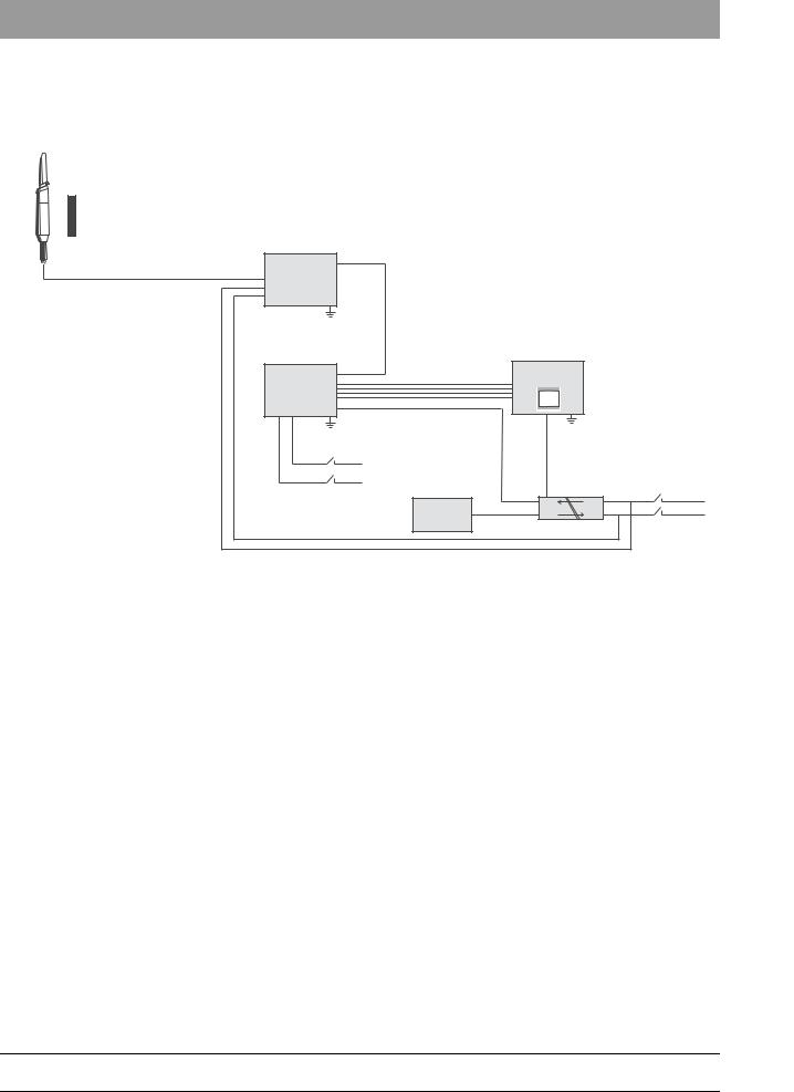
2.3.5Block diagrams ProFeel with SIVISION 2 SIROCAM 2 without PC connection to ProFeel
Camera on monitor
N
Magnet in holder
S
|
S video |
|
|
|
SIROCAM |
|
|
|
|
Box |
|
|
|
|
|
S video |
|
Monitor |
|
VGA |
VGA |
|
LC display |
|
|
|
|
||
converter |
|
|
|
|
Network |
|
|
|
|
|
|
|
12VDC |
|
|
TV |
|
|
Power switch |
|
Still/live image |
|
|
|
|
|
|
in compact |
|
|
White screen |
|
|
|
|
|
|
box |
|
|
|
|
|
|
|
|
12VDC |
|
|
|
Fan |
12VDC |
4kV |
Network |
|
|
NM |
|
|
SIROCAM 2 with PC connection to ProFeel
Camera on monitor |
Monitor |
Monitor |
N |
LC display |
PC |
|
|
Magnet in holder
S
|
|
|
|
|
|
VGA |
|
|
|
|
|
VGA |
|
|
|
|
|
|
|
Graphics card |
|
SIROCAM |
S video |
|
|
S video |
Frame grabber |
|
|
|
|
|
||
|
|
|
|
|
|
|
|
Box |
RS232 |
|
|
RS232 |
IO |
|
|
|
|
|||
|
|
|
|
|
|
|
|
|
|
|
|
|
PC |
|
|
TV |
|
12VDC |
|
|
|
|
Still/live image |
|
|
|
|
Network |
|
|
|
|
|
|
|
|
|
|
|
|
|
|
|
Fan |
12VDC |
4kV |
|
Network |
|
|
|
NM |
|
|
|
|
|
|
|
|
|
Power switch |
|
|
|
|
|
|
in compact |
|
|
|
|
|
|
box |
bеЦдблЬ
59 07 097 D 3322 |
2 – 11 |
D 3322.076.02.04.02 10.2004 |
3 SIVISION 3
C1+
C2+
C3+
C4+
C5+
C8+
M1+
Assistant element: C3+/C4+/C5+
C6/C8
ProFeel
SIVISION 3 Kompakt version
SIVISION 3
|
|
|
|
|
3.1 |
Function of the camera |
|
|
|
|
|
|
|
The SIVISION 3 video application is offered with two camera types: |
|
|
|
|
|
|
|
The SIROCAM 3/C is designed for integration in all units. The C3+/C4+/C5+ |
|
|
|
|
|
|
|
can also be integrated in the assistant element. There is also a compact so- |
|
|
|
|
|
|
|
lution with the SIROCAM 3/C, which can be attached to units that are al- |
|
|
|
|
|
|
|
ready installed. |
|
|
|
|
|
|
|
The SIROCAM 2 was offered for the C1+ and C2+ units until 03/2003. |
|
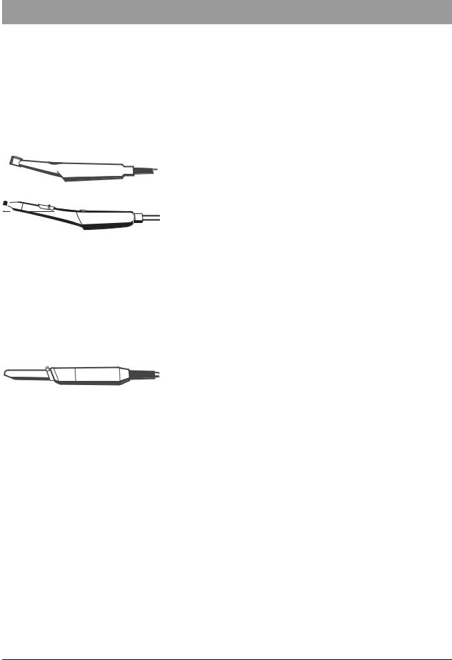
SIROCAM C |
|
The SIROCAM C is an intraoral camera designed especially for the range |
|||||
|
|
|
|
|
|
close to the teeth and the smile line. |
|
|
|
|
|
|
|
|
|
SIROCAM 3 |
|
The SIROCAM 3 is the successor to the SIROCAM 2. |
|||||
|
|
|
|
|
|
The optical system was improved and the electronic concept of the |
|
|
|
|
|
|
|
SIROCAM C was adopted. For example, the interface between the |
|
|
|
|
|
|
|
SIROCAM 3 and the SIROCAM C is identical. |
|
|
|
|
|
|
|
For the SIROCAM 3 and the SIROCAM C: |
|
|
|
|
|
|
|
The object is illuminated by white LEDs. These LEDs heat up the lens of the |
|
|
|
|
|
|
|
camera. This prevents the lens from misting over during treatment. |
|
|
|
|
|
|
|
The camera has an internal quad image memory. The SIROCAM 3/C can be |
|
|
|
|
|
|
|
supplied with a direct voltage of 8.5 to 12VDC. The control signals reach the |
|
|
|
|
|
|
|
camera from the treatment centers or from the PC via a serial interface. |
|
|
|
|
|
|
|
In treatment centers without a serial interface, the camera can also be con- |
|
|
|
|
|
|
|
trolled through discrete inputs. A reed contact integrated in the camera |
|
|
|
|
|
|
|
enables operation through an additional holder mounted on the instrument |
|
|
|
|
|
|
|
rack. The camera is switched on or off by a magnet in the instrument holder. |
|
SIROCAM 2 (discontinued 03/03) |
|
The SIROCAM 2 is characterized by a high-quality optical system. The hous- |
|||||
|
|
|
|
|
|
ing is made of titanium. The lens protective sleeve can be removed and ster- |
|
|
|
|
|
|
|
ilized. The lighting is located in the dentist element and is guided through a |
|
|
|
|
|
|
|
||
|
|
|
|
|
|
fiber-optic cable to the camera head. It is intended for the range close to the |
|
teeth, the smile line and the full face range. The distance adjustment is continuously variable.
The quad image memory is not located in the camera, but on the camera module integrated in the dentist element.
A reed contact integrated in the camera enables operation through an additional holder mounted on the instrument rack. The camera is switched on or off by a magnet in the instrument holder.
To compensate for camera-specific influences on the color settings, data is stored in the camera head. With the introduction of SIVISION 3, apart from a data record for the analog camera PCB KB, a separate data record for the digital PCB AD 2 is stored in the camera. These cameras are identified by the suffix “B” at the end of their serial number. An additional data record can be determined and stored with the white balance function, especially when using cameras featuring only an analog data record (without “B” suffix) in SIVISION 3 configurations. Thus it is possible to optimize the color setting on existing SIROCAM 2 cameras in dental practices on treatment centers with SIVISION 3.
3 – 2 |
59 07 097 D 3322 |
D 3322.076.02.04.02 10.2004 |
|
|
|
Loading...