


 Loading...
SHARP LC-C4067U, LC-C4067UN, LC-40E67UN, LC-40E77UN, LC-46E77UN Service Manual
...LC-C4067U/N,LC-40E67UN,LC-40/46/52E77UN,LC-C46/5277UN,LC-46/52SB57UN
SERVICE MANUAL
LC-C4067U LC-C4067UN LC-40E67UN LC-40E77UN
LC-46E77UN LC-52E77UN LC-C4677UN LC-C5277UN
LC-46SB57UN LC-52SB57UN
No. S49Y7LC4067U/
LCD COLOR TELEVISION
LC-C4067U
LC-C4067UN
LC-40E67UN
LC-40E77UN
LC-46E77UN
LC-52E77UN
LC-C4677UN
LC-C5277UN
LC-46SB57UN MODELS LC-52SB57UN
In the interests of user-safety (Required by safety regulations in some countries) the set should be restored to its original condition and only parts identical to those specified should be used.
OUTLINE
This Service Manual covers the differences from LC-40E67U, LC-40E77U and LC-46E77U, LC-52E77U and LC-46SB57U, LC-52SB57U. For other technical information, refer to the LC-40E67U, LC-40E77U (No. S39X4LC40E67U) / LC-46E77U, LC-52E77U (No. S37X3LC46E77U) / LC-46SB57U, LC-52SB57U (No. S49Y6LC46SB57) Service Manual.
CONTENTS
OUTLINE AND DIFFERENCES FROM BASE MODEL |
Parts Guide |
OUTLINE.................................................................... |
i |
DIFFERENCES FROM BASE MODEL...................... |
i |
SAFETY PRECAUTION |
|
IMPORTANT SERVICE SAFETY |
|
PRECAUTION........................................................... |
iii |
PRECAUTIONS A PRENDRE LORS DE LA |
|
REPARATION .......................................................... |
iv |
PRECAUTIONS FOR USING LEAD-FREE |
|
SOLDER ................................................................... |
v |
CHAPTER 1. ADJUSTMENT |
1-1 |
[1] ADJUSTMENT PROCEDURE ............................... |
Parts marked with "  " are important for maintaining the safety of the set. Be sure to replace these parts with specified ones for maintaining the safety and performance of the set.
This document has been published to be used for after sales service only.
The contents are subject to change without notice.
LC-C4067U/N,LC-40E67UN,LC-40/46/52E77UN,LC-C46/5277UN,LC-46/52SB57UN
OUTLINE AND DIFFERENCES FROM BASE MODEL
OUTLINE
This Service Manual covers the differences from LC-40E67U, LC-40E77U and LC-46E77U, LC-52E77U and LC-46SB57U, LC-52SB57U. For other technical information, refer to the LC-40E67U, LC-40E77U (No. S39X4LC40E67U) / LC-46E77U, LC-52E77U (No. S37X3LC46E77U) / LC46SB57U, LC-52SB57U (No. S49Y6LC46SB57) Service Manual.
DIFFERENCES FROM BASE MODEL
LIST OF CHANGED PARTS (LC-C4067U)(LC-40E67UN)(LC-C4067UN)(LC-40E77UN)
|
|
|
|
LC-C4067U |
|
|
|
|
LC-40E67U |
LC-40E67UN |
Note |
Ref. No. |
|
Description |
LC-40E77U |
LC-C4067UN |
|
|
|
|
(No. S39X4LC40E67U) |
LC-40E77UN |
|
|
|
|
|
(No. S49Y7LC4067U/) |
|
PRINTED WIRING BOARD ASSEMBLIES |
|
|
|||
|
|
KEY Unit |
DUNTKE266FM02 |
← |
— |
|
|
|
|
DUNTKF030FM16 |
|
|
|
|
DUNTKF030FM10 |
(LC-C4067U) |
|
|
|
MAIN Unit |
(LC-40E67U) |
DUNTKF030FM17 |
No internal parts changed |
|
|
|
(LC-40E67UN)(LC-C4067UN) |
||
|
|
|
|
|
|
|
|
|
DUNTKF030FM14 |
DUNTKF030FM17 |
|
|
|
|
(LC-40E77U) |
(LC-40E77UN) |
|
|
|
R/C, LED Unit |
DUNTKF096FM01 |
← |
— |
|
|
POWER Unit |
RDENCA354WJQZ |
← |
— |
|
|
|
|
|
|
LCD PANEL |
|
|
|
|
|
|
|
|
|
← |
— |
|
|
|
R1LK400D3LW10Z |
(LC-C4067U) |
|
|
|
|
|
||
|
|
40"LCD Panel Module |
(LC-40E67U) |
R1LK400D3LW50Z |
Change |
|
|
|
(LC-40E67UN)(LC-C4067UN) |
||
|
|
|
|
|
|
|
|
|
R1LK400D3LW20Z |
R1LK400D3LW60Z |
Change |
|
|
|
(LC-40E77U) |
(LC-40E77UN) |
|
|
|
|
|
||
|
|
|
|
|
|
CABINET AND MECHANICAL PARTS
Please refer to a Parts list
PACKING PARTS, ACCESSORIES
Please refer to a Parts list
i

LC-C4067U/N,LC-40E67UN,LC-40/46/52E77UN,LC-C46/5277UN,LC-46/52SB57UN
LIST OF CHANGED PARTS (LC-46E77UN)(LC-52E77UN)(LC-C4677UN)(LC-C5277UN)
|
|
|
|
LC-46E77UN |
|
|
|
|
LC-46/52E77U |
LC-52E77UN |
Note |
Ref. No. |
|
Description |
LC-C4677UN |
||
|
(No. S37X3LC46E77U) |
||||
|
|
|
LC-C5277UN |
|
|
|
|
|
|
|
|
|
|
|
|
(No. S49Y7LC4067U/) |
|
PRINTED WIRING BOARD ASSEMBLIES |
|
|
|||
|
|
KEY Unit |
DUNTKE266FM02 |
← |
— |
|
|
MAIN Unit |
DUNTKE833FM03 |
DUNTKE833FM07 |
No internal parts changed |
|
|
R/C, LED Unit |
DUNTKF096FM01 |
← |
— |
|
|
POWER Unit |
RDENCA336WJQZ |
← |
— |
|
|
|
|
|
|
LCD PANEL |
|
|
|
|
|
|
|
46"LCD Panel Module |
R1LK460D3LW80Z |
R1LK460D3LW90Z |
Change |
|
|
(LC-46E77U) |
(LC-46E77UN)(LC-C4677UN) |
||
|
|
|
|
||
|
|
52"LCD Panel Module |
R1LK520D3LW80Z |
R1LK520D3LW90Z |
Change |
|
|
(LC-52E77U) |
(LC-52E77UN)(LC-C5277UN) |
||
|
|
|
|
||
|
|
|
|
|
|
CABINET AND MECHANICAL PARTS
Please refer to a Parts list
PACKING PARTS, ACCESSORIES
Please refer to a Parts list
LIST OF CHANGED PARTS (LC-46SB57UN)(LC-52SB57UN)
Ref. No. |
|
Description |
LC-46/52SB57U |
LC-46/52SB57UN |
Note |
|
(No. S49Y6LC46SB57) |
(No. S49Y7LC4067U/) |
|||
|
|
|
|
||
PRINTED WIRING BOARD ASSEMBLIES |
|
|
|||
|
|
KEY Unit |
DUNTKE266FM02 |
← |
— |
|
|
MAIN Unit |
DUNTKE833FM05 |
DUNTKE833FM07 |
No internal parts changed |
|
|
R/C, LED Unit |
DUNTKE264FM02 |
← |
— |
|
|
POWER Unit |
RDENCA336WJQZ |
← |
— |
|
|
|
|
|
|
LCD PANEL |
|
|
|
|
|
|
|
46"LCD Panel Module |
R1LK460D3LW80Z |
R1LK460D3LW90Z |
Change |
|
|
(LC-46SB57U) |
(LC-46SB57UN) |
||
|
|
|
|
||
|
|
52"LCD Panel Module |
R1LK520D3LW80Z |
R1LK520D3LW90Z |
Change |
|
|
(LC-52SB57U) |
(LC-52SB57UN) |
||
|
|
|
|
||
|
|
|
|
|
|
CABINET AND MECHANICAL PARTS
Please refer to a Parts list
PACKING PARTS, ACCESSORIES
Please refer to a Parts list
ii

LC-C4067U/N,LC-40E67UN,LC-40/46/52E77UN,LC-C46/5277UN,LC-46/52SB57UN
SAFETY PRECAUTION
IMPORTANT SERVICE SAFETY PRECAUTION

 Service work should be performed only by qualified service technicians who are thoroughly familiar with all safety checks and the servicing guidelines which follow:
WARNING
1.For continued safety, no modification of any circuit should be attempted.
2.Disconnect AC power before servicing.
CAUTION: FOR CONTINUED PROTECTION AGAINST A RISK OF FIRE REPLACE ONLY WITH SAME TYPE FUSE.
LC-C4067U
LC-40E67UN
LC-C4067UN
LC-40E77UN
F7101 (250V 6.3A)
F7105 (250V 1A)
LC-46E77UN
LC-52E77UN
LC-C4677UN
LC-C5277UN
LC-46SB57UN
LC-52SB57UN
F7000 (250V 6.3A)
•Using two clip leads, connect a 1.5k ohm, 10 watt resistor paralleled by a 0.15µF capacitor in series with all exposed metal cabinet parts and a known earth ground, such as electrical conduit or electrical ground connected to an earth ground.
•Use an AC voltmeter having with 5000 ohm per volt, or higher, sensitivity or measure the AC voltage drop across the resistor.
•Connect the resistor connection to all exposed metal parts having a return to the chassis (antenna, metal cabinet, screw heads, knobs and control shafts, escutcheon, etc.) and measure the AC voltage drop across the resistor.
All checks must be repeated with the AC cord plug connection reversed. (If necessary, a nonpolarized adaptor plug must be used only for the purpose of completing these checks.)
Any reading of 0.75 Vrms (this corresponds to 0.5 mA rms AC.) or more is excessive and indicates a potential shock hazard which must be corrected before returning the monitor to the owner.
DVM
AC SCALE
BEFORE RETURNING THE RECEIVER (Fire &
Shock Hazard)
Before returning the receiver to the user, perform the following safety checks:
3.Inspect all lead dress to make certain that leads are not pinched, and check that hardware is not lodged between the chassis and other metal parts in the receiver.
4.Inspect all protective devices such as non-metallic control knobs, insulation materials, cabinet backs, adjustment and compartment covers or shields, isolation resistor-capacitor networks, mechanical insulators, etc.
5.To be sure that no shock hazard exists, check for leakage current in the following manner.
•Plug the AC cord directly into a 120 volt AC outlet.
1.5k ohm
10W
0.15 µF
TEST PROBE
TO EXPOSED |
CONNECT TO |
METAL PARTS |
KNOWN EARTH |
|
GROUND |
///////////////////////////////////////////////////////////////////////////////////////////////////////////////////////////////////////////////////////////////////////////////////////////////////////////////////////////////////////////
SAFETY NOTICE
Many electrical and mechanical parts in LCD color television have special safety-related characteristics.
These characteristics are often not evident from visual inspection, nor can protection afforded by them be necessarily increased by using replacement components rated for higher voltage, wattage, etc.
Replacement parts which have these special safety characteristics are identified in this manual; electrical components having such features
are identified by " " and shaded areas in the Replacement Parts List and Schematic Diagrams.
For continued protection, replacement parts must be identical to those used in the original circuit.
The use of a substitute replacement parts which do not have the same safety characteristics as the factory recommended replacement parts shown in this service manual, may create shock, fire or other hazards.
///////////////////////////////////////////////////////////////////////////////////////////////////////////////////////////////////////////////////////////////////////////////////////////////////////////////////////////////////////////
iii

LC-C4067U/N,LC-40E67UN,LC-40/46/52E77UN,LC-C46/5277UN,LC-46/52SB57UN
PRECAUTIONS A PRENDRE LORS DE LA REPARATION
 Ne peut effectuer la réparation qu' un technicien spécialisé qui s'est parfaitement accoutumé à toute vérification de sécurité et aux conseils suivants.

 AVERTISSEMENT
1.N'entreprendre aucune modification de tout circuit. C'est dangereux.
2.Débrancher le récepteur avant toute réparation.
PRECAUTION: POUR LA PROTECTION CONTINUE CONTRE LES RISQUES D'INCENDIE, REMPLACER LE FUSIBLE
LC-C4067U
LC-40E67UN
LC-C4067UN
LC-40E77UN
F7101 (250V 6.3A)
F7105 (250V 1A)
LC-46E77UN
LC-52E77UN
LC-C4677UN
LC-C5277UN
LC-46SB57UN
LC-52SB57UN
F7000 (250V 6.3A)
•A l'aide de deux fils à pinces, brancher une résistance de 1.5 kΩ 10 watts en parallèle avec un condensateur de 0.15µF en série avec toutes les pièces métalliques exposées du coffret et une terre connue comme une conduite électrique ou une prise de terre branchée à la terre.
•Utiliser un voltmètre CA d'une sensibilité d'au moins 5000Ω/V pour mesurer la chute de tension en travers de la résistance.
•Toucher avec la sonde d'essai les pièces métalliques exposées qui présentent une voie de retour au châssis (antenne, coffret métallique, tête des vis, arbres de commande et des boutons, écusson, etc.) et mesurer la chute de tension CA en-travers de la résistance. Toutes les vérifications doivent être refaites après avoir inversé la fiche du cordon d'alimentation. (Si nécessaire, une prise d'adpatation non polarisée peut être utilisée dans le but de terminer ces vérifications.)
La tension de pointe mesurèe ne doit pas dépasser 0.75V (correspondante au courant CA de pointe de 0.5mA).
Dans le cas contraire, il y a une possibilité de choc électrique qui doit être supprimée avant de rendre le récepteur au client.

 VERIFICATIONS CONTRE L'INCEN-DIE ET LE CHOC ELECTRIQUE
Avant de rendre le récepteur à l'utilisateur, effectuer les vérifications suivantes.
3.Inspecter tous les faisceaux de câbles pour s'assurer que les fils ne soient pas pincés ou qu'un outil ne soit pas placé entre le châssis et les autres pièces métalliques du récepteur.
4.Inspecter tous les dispositifs de protection comme les boutons de commande non-métalliques, les isolants, le dos du coffret, les couvercles ou blindages de réglage et de compartiment, les réseaux de résistancecapacité, les isolateurs mécaniques, etc.
5.S'assurer qu'il n'y ait pas de danger d'électrocution en vérifiant la fuite de courant, de la facon suivante:
•Brancher le cordon d'alimentation directem-ent à une prise de courant de 120V. (Ne pas utiliser de transformateur d'isolation pour cet essai).
DVM
 ECHELLE CA
1.5k ohm
10W
0.15 µF SONDE D'ESSAI
AUX PIECES |
BRANCHER A UNE |
|
METALLIQUES |
||
TERRE CONNUE |
||
EXPOSEES |
||
|
/////////////////////////////////////////////////////////////////////////////////////////////////////////////////////////////////////////////////////////////////////////////////////////////////////////////////////////////////////////////
AVIS POUR LA SECURITE
De nombreuses pièces, électriques et mécaniques, dans les téléviseur ACL présentent des caractéristiques spéciales relatives à la sécurité, qui ne sont souvent pas évidentes à vue. Le degré de protection ne peut pas être nécessairement augmentée en utilisant des pièces de remplacement étalonnées pour haute tension, puissance, etc.
Les pièces de remplacement qui présentent ces caractéristiques sont identifiées dans ce manuel; les pièces électriques qui présentent ces particularités sont identifiées par la marque " " et hachurées dans la liste des pièces de remplacement et les diagrammes schématiques.
Pour assurer la protection, ces pièces doivent être identiques à celles utilisées dans le circuit d'origine. L'utilisation de pièces qui n'ont pas les mêmes caractéristiques que les pièces recommandées par l'usine, indiquées dans ce manuel, peut provoquer des électrocutions, incendies, radiations X ou autres accidents.
/////////////////////////////////////////////////////////////////////////////////////////////////////////////////////////////////////////////////////////////////////////////////////////////////////////////////////////////////////////////
iv

LC-C4067U/N,LC-40E67UN,LC-40/46/52E77UN,LC-C46/5277UN,LC-46/52SB57UN
PRECAUTIONS FOR USING LEAD-FREE SOLDER
Employing lead-free solder
•“PWBs” of this model employs lead-free solder. The LF symbol indicates lead-free solder, and is attached on the PWBs and service manuals. The alphabetical character following LF shows the type of lead-free solder.
Example:
|
|
|
|
|
|
|
|
|
|
|
|
|
|
|
|
|
|
|
|
|
|
|
|
Indicates lead-free solder of tin, silver and copper. |
Indicates lead-free solder of tin, silver and copper. |
||||||||||
Using lead-free wire solder
•When fixing the PWB soldered with the lead-free solder, apply lead-free wire solder. Repairing with conventional lead wire solder may cause damage or accident due to cracks.
As the melting point of lead-free solder (Sn-Ag-Cu) is higher than the lead wire solder by 40 °C, we recommend you to use a dedicated soldering bit, if you are not familiar with how to obtain lead-free wire solder or soldering bit, contact our service station or service branch in your area.
Soldering
•As the melting point of lead-free solder (Sn-Ag-Cu) is about 220 °C which is higher than the conventional lead solder by 40 °C, and as it has poor solder wettability, you may be apt to keep the soldering bit in contact with the PWB for extended period of time. However, Since the land may be peeled off or the maximum heat-resistance temperature of parts may be exceeded, remove the bit from the PWB as soon as you confirm the steady soldering condition.
Lead-free solder contains more tin, and the end of the soldering bit may be easily corroded. Make sure to turn on and off the power of the bit as required.
If a different type of solder stays on the tip of the soldering bit, it is alloyed with lead-free solder. Clean the bit after every use of it. When the tip of the soldering bit is blackened during use, file it with steel wool or fine sandpaper.
•Be careful when replacing parts with polarity indication on the PWB silk.
Lead-free wire solder for servicing
PARTS CODE |
PRICE |
PART |
DESCRIPTION |
|
RANK |
DELIVERY |
|||
|
|
|||
ZHNDAi123250E |
BL |
J |
φ0.3mm 250g (1roll) |
|
ZHNDAi126500E |
BK |
J |
φ0.6mm 500g (1roll) |
|
ZHNDAi12801KE |
BM |
J |
φ1.0mm 1kg (1roll) |
v
LC-C4067U/N,LC-40E67UN,LC-40/46/52E77UN,LC-C46/5277UN,LC-46/52SB57UN
CHAPTER 1. ADJUSTMENT
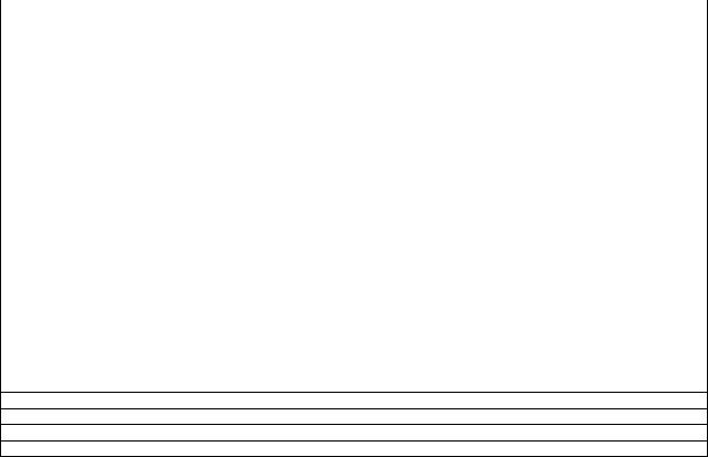
[1] ADJUSTMENT PROCEDURE
1. Model number ID plug
(LC-C4067U)(LC-40E67UN)(LC-C4067UN)(LC-40E77UN)
Model numbers are identified by inserting the destination ID plug (QCNCMA275WJQZ) in its specified slot of the destination ID connector SC9002/ SC9003 (QCNCWA715WJQZY).
1 |
12 |
|
1 |
6 |
1 |
15 |
|
1 |
|
|
|
|
|
|
|
4 |
|
|
|
|
|
|
1 |
|
|
|
|
|
|
|
|
|
|
|
|
|
|
|
41 |
SC9003 |
SC9002 |
C5 |
|
|
|
|
|
|
|
|
|
|
|
||
|
HDMI |
MAIN Unit |
|
DDR |
|
|
|
|
|
|
|
|
|||
HDMI |
|
|
Position |
|
|
||
|
|
|
|
|
|
|
|
|
|
|
TUNER |
|
|
||
PC Audio IN |
Optical |
|
|
|
|
|
|
out |
L/R out |
|
|
|
|
|
|
V/LR |
S-Video |
|
|
|
|
|
|
|
|
|
|
|
|
|
|
USB |
|
|
|
|
|
|
|
Analog RGB RS-232C |
1 |
|
|
10 |
1 |
4 |
|
|
|
|
|
|
|
||
Destination ID connector locations
SC9002 SC9003
LC-C4067U
LC-40E67UN
LC-C4067UN
LC-40E77UN
Plug locations
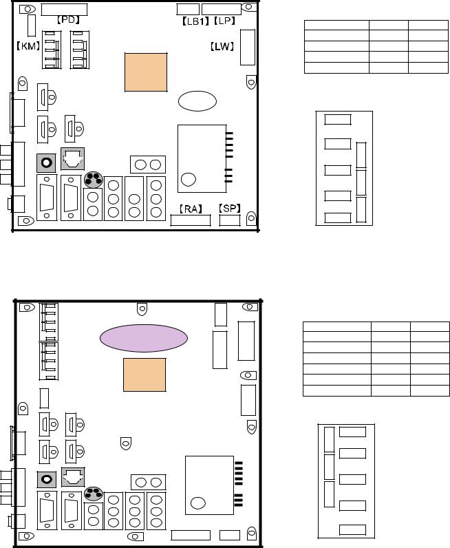
2. Model number ID plug
(LC-46E77UN)(LC-52E77UN)(LC-C4677UN)(LC-C5277UN)(LC-46SB57UN)(LC-52SB57UN)
Model numbers are identified by inserting the destination ID plug (QCNCMA275WJQZ) in its specified slot of the destination ID connector SC9201/ SC9202 (QCNCWA715WJQZY).
|
|
|
|
LB1 |
1 |
PD |
|
|
|
|
|
|
6 |
||
|
SC9202 |
|
|
|
|
|
1 |
|
|
DDR |
LP |
1 |
|
|
|
|
|
|
|
|
|||
|
|
|
position |
|
|
|
|
|
|
|
|
|
|
|
12 |
|
|
|
|
|
15 |
|
|
|
SC9201 |
|
MDK |
|
|
|
|
1 KM |
|
MAIN Unit |
|
|
|
1 |
|
4 |
HDMI |
|
|
|
41 |
||
|
|
|
E833 |
|
LW |
||
HDMI |
|
|
|
|
|
|
|
PC Audio IN |
Optical |
|
TUNER |
|
|
||
out |
L/R |
|
|
|
|
||
|
|
|
|
|
|
||
V/LR |
|
S-Video |
|
|
|
|
|
|
|
|
|
|
|
|
|
USB |
|
|
|
RA |
SP |
|
|
|
|
|
|
|
|||
|
RS-232C |
|
1 |
10 |
1 |
4 |
|
Analog RGB |
|
|
|||||
|
|
|
|
|
|
||
|
|
|
|
|
|
1 – 1 |
|
Destination ID connector locations
SC9201 SC9202
LC-46E77UN
LC-52E77UN
LC-C4677UN
LC-C5277UN
LC-46SB57UN
LC-52SB57UN
Plug locations
LC-C4067U/N,LC-40E67UN,LC-40/46/52E77UN,LC-C46/5277UN,LC-46/52SB57UN
1 – 2

LC-C4067U/N,LC-40E67UN,LC-40/46/52E77UN,LC-C46/5277UN,LC-46/52SB57UN
PARTS GUIDE
LC-C4067U
LC-C4067UN
LC-40E67UN
LC-40E77UN
LC-46E77UN
LC-52E77UN
LC-C4677UN
LC-C5277UN
LC-46SB57UN
LC-52SB57UN
Note:
The reference numbers on the PWB are arranged in alphabetical order.
No. S49Y7LC4067U/
LCD COLOR TELEVISION
LC-C4067U
LC-C4067UN
LC-40E67UN
LC-40E77UN
LC-46E77UN
LC-52E77UN
LC-C4677UN
LC-C5277UN
LC-46SB57UN MODELS LC-52SB57UN
CONTENTS
[1]PRINTED WIRING BOARD ASSEMBLIES (LC-C4067U)(LC-40E67UN)(LC-C4067UN)(LC-40E77UN)
[2]PRINTED WIRING BOARD ASSEMBLIES (LC-46E77UN)(LC-52E77UN)(LC-C4677UN) (LC-C5277UN)(LC-46SB57UN)(LC-52SB57UN)
[3]LCD PANEL (LC-C4067U)(LC-40E67UN)(LC-C4067UN)(LC-40E77UN)
[4]LCD PANEL (LC-46E77UN)(LC-52E77UN)(LC-C4677UN) (LC-C5277UN)(LC-46SB57UN)(LC-52SB57UN)
[5]CABINET AND MECHANICAL PARTS (LC-C4067U)(LC-40E67UN)(LC-C4067UN)(LC-40E77UN)
[6]CABINET AND MECHANICAL PARTS (LC-46E77UN)(LC-C4677UN)
[7]CABINET AND MECHANICAL PARTS (LC-52E77UN)(LC-C5277UN)
[8]CABINET AND MECHANICAL PARTS (LC-46SB57UN)
[9]CABINET AND MECHANICAL PARTS (LC-52SB57UN)
[10]LCD MODULE Assembly (LC-C4067U)(LC-40E67UN)(LC-C4067UN)(LC-40E77UN)
[11]LCD MODULE Assembly (LC-46E77UN)(LC-C4677UN)(LC-46SB57UN)
[12]LCD MODULE Assembly (LC-52E77UN)(LC-C5277UN)(LC-52SB57UN)
[13]SUPPLIED ACCESSORIES (LC-C4067U)(LC-C4067UN)(LC-C4677UN) (LC-C5277UN)(LC-40E67UN)(LC-40E77UN) (LC-46E77UN)(LC-52E77UN)
[14]SUPPLIED ACCESSORIES (LC-46SB57UN)(LC-52SB57UN)
[15]PACKING PARTS (NOT REPLACEMENT ITEM) (LC-C4067U)(LC-40E67UN)(LC-C4067UN)(LC-40E77UN)
[16]PACKING PARTS (NOT REPLACEMENT ITEM) (LC-46E77UN)(LC-52E77UN)(LC-C4677UN) (LC-C5277UN)
[17]PACKING PARTS (NOT REPLACEMENT ITEM) (LC-46SB57UN)
[18]PACKING PARTS (NOT REPLACEMENT ITEM) (LC-52SB57UN)
Parts marked with "  " are important for maintaining the safety of the set. Be sure to replace these parts with specified ones for maintaining the safety and performance of the set.
This document has been published to be used for after sales service only.
The contents are subject to change without notice.

LC-C4067U/N,LC-40E67UN,LC-40/46/52E77UN,LC-C46/5277UN,LC-46/52SB57UN
NO. |
PARTS CODE |
PRICE |
NEW |
PART |
DESCRIPTION |
|
RANK |
MARK |
DELIVERY |
||||
|
|
|
[1] PRINTED WIRING BOARD ASSEMBLIES (LC-C4067U)(LC-40E67UN)(LC-C4067UN)(LC-40E77UN)
N |
DUNTKE266FM02 |
AH |
N |
X |
KEY Unit |
N |
DUNTKF030FM16 |
BZ |
N |
X |
MAIN Unit (DUNTKF030FM16S)(LC-C4067U) |
N |
DUNTKF030FM17 |
BZ |
N |
X |
MAIN Unit (DUNTKF030FM17S) |
N |
|
|
|
|
(LC-40E67UN)(LC-C4067UN)(LC-40E77UN) |
N |
DUNTKF096FM01 |
AN |
N |
X |
R/C, LED Unit |
N |
RDENCA354WJQZ |
BP |
N |
X |
POWER Unit |
N |
RUNTK4106TPZC |
BP |
|
J |
LCD Control Unit |
N |
|
|
|
|
(LC-C4067U)(LC-40E67UN)(LC-C4067UN) |
N |
RUNTK4159TPZZ |
CD |
|
J |
LCD Control Unit (LC-40E77UN) |
N |
RUNTKA568WJN1 |
BQ |
|
J |
INVERTER Unit |
N |
RUNTKA569WJZZ |
AN |
|
J |
INVERTER GND Unit-1 |
N |
RUNTKA570WJZZ |
AN |
|
J |
INVERTER GND Unit-2 |
[2] PRINTED WIRING BOARD ASSEMBLIES (LC-46E77UN)(LC-52E77UN)(LC-C4677UN)(LC-C5277UN)(LC- 46SB57UN)(LC-52SB57UN)
N |
DUNTKE266FM02 |
AH |
N |
X |
KEY Unit |
N |
DUNTKE833FM07 |
CB |
N |
X |
MAIN Unit (DUNTKE833FM07S) |
N |
DUNTKF096FM01 |
AN |
N |
X |
R/C, LED Unit |
N |
|
|
|
|
(LC-46E77UN)(LC-52E77UN)(LC-C4677UN)(LC-C5277UN) |
N |
DUNTKE264FM02 |
AP |
|
X |
R/C, LED Unit (LC-46SB57UN)(LC-52SB57UN) |
N |
RDENCA336WJQZ |
BR |
|
X |
POWER Unit |
N |
CPWBX4023TPXR |
|
N |
J |
LCD Control Unit |
N |
|
|
|
|
(LC-46E77UN)(LC-C4677UN)(LC-46SB57UN) |
N |
CPWBX4023TPXQ |
|
N |
J |
LCD Control Unit |
N |
|
|
|
|
(LC-52E77UN)(LC-C5277UN)(LC-52SB57UN) |
N |
RUNTKA538WJN1 |
BF |
N |
J |
INVERTER Unit-1 |
N |
|
|
|
|
(LC-46E77UN)(LC-C4677UN)(LC-46SB57UN) |
N |
RUNTKA539WJN1 |
BF |
N |
J |
INVERTER Unit-2 |
N |
|
|
|
|
(LC-46E77UN)(LC-C4677UN)(LC-46SB57UN) |
N |
RUNTKA528WJN1 |
BF |
N |
J |
INVERTER Unit-1 |
N |
|
|
|
|
(LC-52E77UN)(LC-C5277UN)(LC-52SB57UN) |
N |
RUNTKA529WJN1 |
BF |
N |
J |
INVERTER Unit-2 |
N |
|
|
|
|
(LC-52E77UN)(LC-C5277UN)(LC-52SB57UN) |
N |
RUNTKA540WJZZ |
AP |
N |
J |
INVERTER GND Unit-1 |
N |
|
|
|
|
(LC-46E77UN)(LC-C4677UN)(LC-46SB57UN) |
N |
RUNTKA541WJZZ |
AP |
N |
J |
INVERTER GND Unit-2 |
N |
|
|
|
|
(LC-46E77UN)(LC-C4677UN)(LC-46SB57UN) |
N |
RUNTKA530WJZZ |
AP |
N |
J |
INVERTER GND Unit-1 |
N |
|
|
|
|
(LC-52E77UN)(LC-C5277UN)(LC-52SB57UN) |
N |
RUNTKA531WJZZ |
AP |
N |
J |
INVERTER GND Unit-2 |
N |
|
|
|
|
(LC-52E77UN)(LC-C5277UN)(LC-52SB57UN) |
[3] LCD PANEL (LC-C4067U)(LC-40E67UN)(LC-C4067UN)(LC-40E77UN)
N |
R1LK400D3LW10Z |
DS |
N |
X |
40"LCD Panel Module (LK400D3LW10Z) |
N |
|
|
|
|
(LC-C4067U) |
N |
R1LK400D3LW50Z |
DL |
N |
X |
40"LCD Panel Module (LK400D3LW50Z) |
N |
|
|
|
|
(LC-40E67UN)(LC-C4067UN) |
N |
R1LK400D3LW60Z |
DS |
N |
X |
40"LCD Panel Module (LK400D3LW60Z) |
N |
|
|
|
|
(LC-40E77UN) |
[4] LCD PANEL (LC-46E77UN)(LC-52E77UN)(LC-C4677UN)(LC-C5277UN)(LC-46SB57UN)(LC-52SB57UN)
N |
R1LK460D3LW90Z |
EC |
N |
X |
46"LCD Panel Module (LK460D3LW90Z) |
N |
|
|
|
|
(LC-46E77UN)(LC-C4677UN)(LC-46SB57UN) |
N |
R1LK520D3LW90Z |
|
N |
X |
52"LCD Panel Module (LK520D3LW90Z) |
N |
|
|
|
|
(LC-52E77UN)(LC-C5277UN)(LC-52SB57UN) |
2

LC-C4067U/N,LC-40E67UN,LC-40/46/52E77UN,LC-C46/5277UN,LC-46/52SB57UN
[5] CABINET AND MECHANICAL PARTS (LC-C4067U)(LC-40E67UN)(LC-C4067UN)(LC-40E77UN)
LCD Module Assembly
42
26
1
36
1-1
7
37
1-5
1-4
 31
31
1-2-1
1-2-2
33
POWER Unit
34 |
47 |
13
27
 45 12 13 11
16
17
18
R/C, LED Unit |
44 |
9 |
38 |
|
|
||
|
|
|
|
1-3 |
|
6 |
|
|
|
|
|
|
2-1 |
|
|
4-1 4-2 |
|
|
46 |
|
|
|
|
|
|
|
8 |
44
KEY Unit 4 |
|
|
|
43 |
|
1-2 |
|
|
|
||
|
2 |
|
|
|
|
|
|
|
|
2-2 |
|
30 |
|
|
|
|
|
R |
35 |
20 |
|
|
|
|
|
|
|
||
* LC-40E77UN only |
|
|
21 |
|
|
R |
|
|
|
||
|
23 |
45 |
|
||
29 |
|
39 |
|||
|
20 |
|
|||
|
|
|
|||
|
|
|
|
||
* LC-40E77UN only |
45 |
|
41 |
|
|
21 |
24 |
45 |
|||
|
|
||||
45 |
|
|
19 |
|
|
11 |
25 |
21 |
|
|
|
32 |
28 |
|
|
48 |
|
|
|
|
|||
15 |
|
|
20 |
3-2 |
|
|
|
|
|||
MAIN Unit |
|
|
|
3-1 |
|
|
|
|
|
3 |
|
14 |
22 |
|
|
|
|
* LC-40E77UN only |
|
|
X5 |
|
|
|
|
|
|
||
40 |
45 |
|
|
|
|
5 |
|
|
|
||
|
|
|
|
||
17 |
|
|
|
|
|
45 |
|
|
|
|
|
10 |
5-3 |
|
|
|
||
17 |
17 |
|
|
|
|
||
|
|
5-1 |
|
17 |
|
5-2 |
|
* LC-C4067U |
|
|
|
LC-40E67UN |
17 |
|
|
LC-C4067UN only |
* LC-40E77UN only |
||
|
3
Loading...