


LC121M2U

1
LC-121M2U
LC-150M2U
LC-121M2U
LC-150M2U
SX8Z8LC-121M2U
SERVICE MANUAL
MODELS LC-121M2U/150M2U
In the interests of user-safety (Required by safety regulations in some countries) the set should be restored to its original
condition and only parts identical to those specified be used.
LC-121M2U
LC-150M2U
LCD AV MONITOR
SERVICE MANUAL
LC-121M2U
LC-150M2U
This document has been published to be used for
after sales service only.
The contents are subject to change without notice.
SHARP CORPORATION
CONTENTS
Page
1. IMPORTANT SERVICE SAFETY PRECAUTION .................................................................................... 2
2. SPECIFICATIONS ................................................................................................................................... 4
3. PART NAMES.......................................................................................................................................... 5
4. DISASSEMBLY OF THE SET.................................................................................................................. 6
5. ADJUSTING PROCEDURE OF EACH SECTION ................................................................................... 8
6. INTEGRATED CIRCUIT TERMINAL ARRANGEMENTS ........................................................................ 19
7. TROUBLE SHOOTING TABLE................................................................................................................ 24
8. CHASSIS LAYOUT .................................................................................................................................. 29
9. SCHEMATIC DIAGRAM .......................................................................................................................... 32
10. BLOCK DIAGRAM ................................................................................................................................... 47
11. PRINTED WIRING BOARD ASSEMBLIES .............................................................................................. 49
12. REPLACEMENT PARTS LIST ................................................................................................................. 54
13. PACKING OF THE SET ........................................................................................................................... 65
MODELS
LCD AV MONITOR
2
LC-121M2U
LC-150M2U
LC-121M2U
LC-150M2U
1. IMPORTANT SERVICE SAFETY PRECAUTION
æ Service work should be perfomed only by qualified service technicians who are
thoroughly familiar with all safety checks and servicing guidelines which follow:
WARNING
1. For continued safety, no modification of any
circuit should be attempted.
2. Disconnect AC power before servicing.
CAUTION
FOR CONTINUED PROTECTION
AGAINST A RISK OF FIRE, REPLACE
ONLY WITH SAME TYPE F701, F703 (1.6A
125V), F702 (2.5A 125V).
BEFORE RETURNING THE RECEIVER
(Fire & Shock Hazard)
Before returning the receiver to the user,
perform the following safety checks:
1. Inspect all lead dress to make certain that leads
are not pinched, and check that hardware is not
lodged between the chassis and other metal
parts in the receiver.
2. Inspect all protective devices such as non-me-
tallic control knobs, insulation materials, cabinet
backs, adjustment and compartment covers or
shields, isolation resistor-capacitor networks,
mechanical insulators, etc.
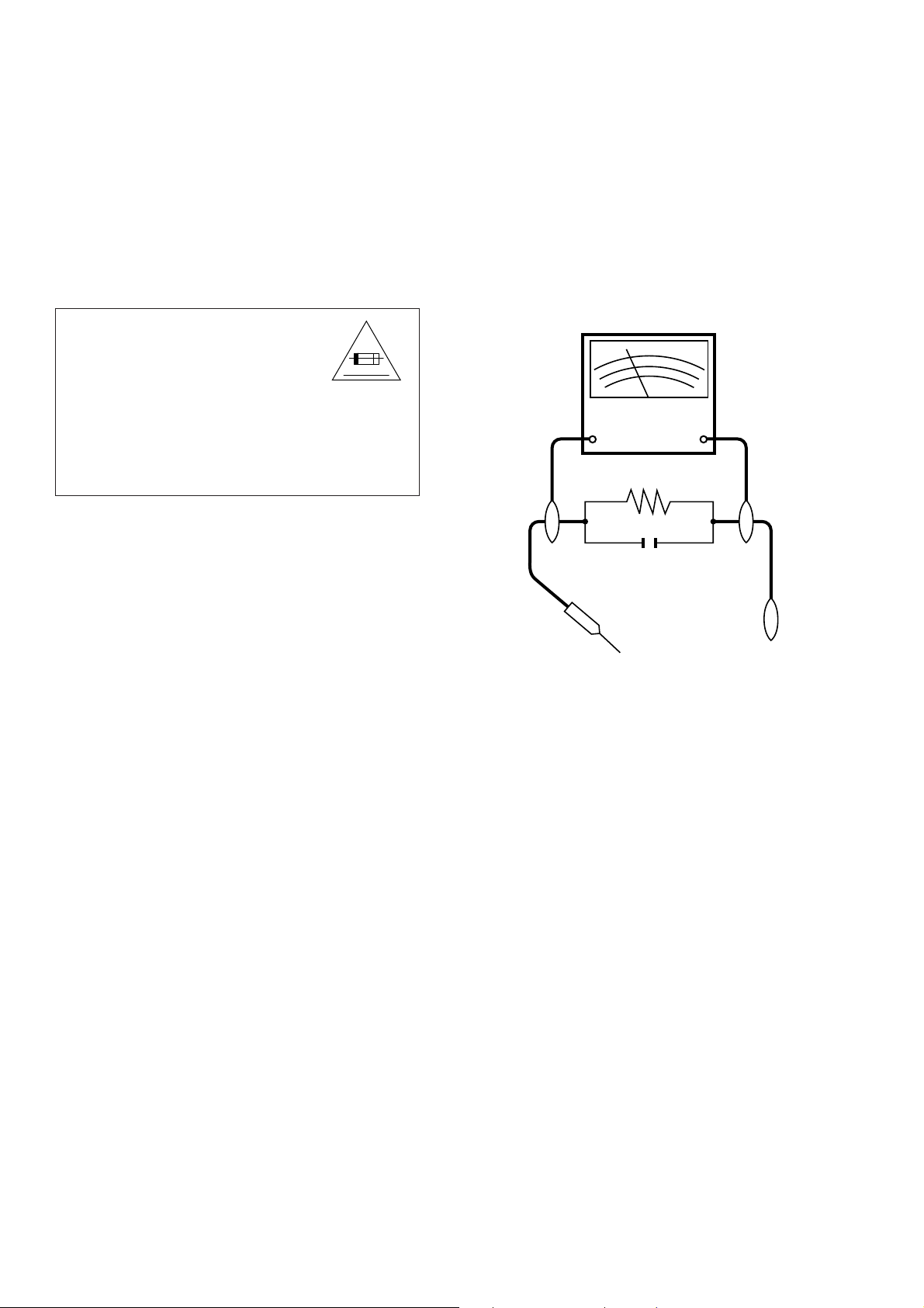
3. To be sure that no shock hazard exists, check for
current in the following manner.
• Plug the AC Adapter directly into a 120-volt AC
outlet, and connect the DC power cable into the
monitor's DC jack. (Do not use an isolation
transformer for this test).
• Using two clip leads, connect a 1.5k ohm, 10
watt resistor paralleled by a 0.15µF capacitor in
series with all exposed metal cabinet parts and
a known earth ground, such as electrical conduit
or electrical ground connected to an earth ground.
• Use an AC voltmeter having with 5000 ohm per
volt, or higher, sensitivity or measure the AC
voltage drop across the resisor.
• Connect the resistor connection to all exposed
metal parts having a return path to the chassis
(antenna, metal cabinet, screw heads, knobs
and control shafts, escutcheon, etc.) and meas-
ure the AC voltage drop across the resistor.
All checks must be repeated with the AC Adap-
tor plug connection reversed.(If necessary, a
nonpolarized adaptor plug must be used only for
the purpose of completing these checks.)
5A 125V
Any reading of 0.3V RMS(this corresponds
to 0.2 milliamp. AC.) or more is excessive and
indicates a potential shock hazard which must
be corrected before returning the receiver to
the owner.
SAFETY NOTICE
Many electrical and mechanical parts in LCD monitor
have special safety-related characteristics.
These characteristics are often not evident from visual
inspection, nor can protection afforded by them be nec-
essarily increased by using replacement components
rated for higher voltage, wattage, etc.
Replacement parts which have these special safety
characteristics are identified in this manual; electrical
components having such features are identified by
“ å” and shaded areas in the
Replacement Parts Lists
and Schematic Diagrams
.
For continued protection, replacement parts must be
identical to those used in the original circuit.
The use of a substitute replacement parts which do not
have the same safety characteristics as the factory
recommended replacement parts shown in this service
manual, may create shock. fire. or other hazards.
TO EXPOSED
METAL PARTS
CONNECT TO
KNOWN EARTH
GROUND
DVM
AC SCALE
1.5k ohms.
10W
0.15 µF
TEST PROBE

3
LC-121M2U
LC-150M2U
LC-121M2U
LC-150M2U
1. PRECAUTIONS A PRENDRE LORS DE LA REPARATION
ÆÆ
ÆÆ
Æ Ne peut effectuer la réparation qu’ un technicien spécialisé qui s’est parfaitement
accoutumé à toute vérification de sécurité et aux conseils suivants.
AVERTISSEMENT
1. N’entreprendre aucune modification de tout cir-
cuit.
C’est dangereux.
2. Débrancher le récepteur avant toute réparation.
PRECAUTION
POUR LA PROTECTION CONTINUE
CONTRE LES RISQUES D’INCENDIE,
REMPLACER LE FUSIBLE PAR UN FUSIBLE
DE MEME TYPE F701, F703 (1.6A 125V), F702
(2.5A 125V).
VERIFICATIONS CONTRE L’INCEN-
DIE ET LE CHOC ELECTRIQUE
Avant de rendre le récepteur à l’utilisateur,
effectuer les vérifications suivantes.
1. Inspecter tous les faisceaux de câbles pour
s’assurer que les fils ne soient pas pincés ou
qu’un outil ne soit pas placé entre le châssis et
les autres pièces métalliques du récepteur.
2. Inspecter tous les dispositifs de protection comme
les boutons de commande non-métalliques, les
isolants, le dos du coffret, les couvercles ou
blindages de réglage et de compartiment, les
réseaux de résistance-capacité, les isolateurs
mécaniques, etc.
3. S’assurer qu’il n’y ait pas de danger
d’électrocution en vérifiant la fuite de courant, de
la facon suivante:
• Brancher l’adaptateur CA dans la prise CA de
120 V et le câble d’alimentation CC dans le jack
du moniteur. (Ne pas utiliser un transformateur
pour cet essai.)
• A l’aide de deux fils à pinces, brancher une
résistance de 1,5kΩ 10 watts en paralléle avec
un condensateur de 0,15µF en série avec toutes
les pièces métalliques exposées du coffret et
une terre connue comme une conduite électrique
ou une prise de terre branchée à la terre.
• Utiliser un voltmètre CA d’une sensibilité d’au
moins 5000Ω/V pour mesurer la chute de ten-
sion en travers de la résistance.
• Raccordez la résistance à toutes les pièces
exposées qui ont un chemin de retour au châssis
(antenne, coffret métallique, têtes de vis, bou-
tons, arbres de commande, emblème, etc) et
mesurez une chute de tension CA à travers la
résistance.
5A 125V
AVIS POUR LA SECURITE
De nombreuses pièces, électriques et mécaniques, dans
les téléviseurs présentent des caractéristiques spéciales
relatives à la sécurité, qui ne sont souvent pas évidentes
à vue. Le degré de protection ne peut pas être
nécessairement augmentée en utilisant des pièces de
remplacement étalonnées pour haute tension, puissance,
etc.
Les pièces de remplacement qui présentent ces
caractéristiques sont identifiées dans ce manuel; les
pièces électriques qui présentent ces particularités sont
identifiées par la marque “ å” et hachurées dans la liste
des pièces de remplacement et les diagrammes
schématiques.
Pour assurer la protection, ces pièces doivent être
identiques à celles utilisées dans le circuit d’origine.
L’utilisation de pièces qui n’ont pas les mêmes
caractéristiques que les pièces recommandées par
l’usine, indiquées dans ce manuel, peut provoquer des
électrocutions, incendies, radiations X ou autres acci-
dents.
0,15 µF
SONDE D'ESSAI
DVM
Echelle CA
1.5 k ohm
10W
AUX PIECES
METALLIQUES
EXPOSEES
BRANCHER A UNE
TERRE CONNUE
Il faut répéter les vérifications en inversant la
connexion de la fiche de l'adaptateur CA (S'il
y a lieu, utilisez une fiche non polarisée pour
seulement compléter ces vérifications.)
Une valeur de 0,3 V RMS ou plus (correspond
à 0,2 mA C.A.) est excessive et implique un
danger de secousse électrique, qui devra être
supprimé avant de retourner l'appareil à
l'utilisateur.

4
LC-121M2U
LC-150M2U
LC-121M2U
LC-150M2U
2. SPECIFICATIONS
Type: LCD display unit (LCD color AV monitor)
Size: 12.1" type (184.3 mm × 245.8 mm) (LC-121M2U)
15" type (305.3 mm × 229.0 mm) (LC-150M2U)
Display System: Transmitting type TN liquid crystal panel.
Driving System: TFT (Thin Film Transistor) active matrix system
Number of Picture Elements: 921,600 (480 (V) × 640 (H) × 3 (RBG) )
Speaker Output: 0.7 W × 2 (Front)
2 W × 1 (Rear)
Speaker: 30 mm × 40 mm (Elliptic) × 2 (Front)
65 mm (Round) × 1 (Rear)
Light Source: Internal Light (Built-in fluorescent lamp)
Connected Terminals: Input: DC12V, VHS, S-VHS, Audio and DVD
Output: VHS, S-VHS, Audio and Headphone
Power Source: AC 100~240·50/60Hz (Connected to AC Adapter)
Power Consumption (Approx.): 38 W (Connected to AC Adapter) (LC-121M2U)
40 W (Connected to AC Adapter) (LC-150M2U)
Operating Temparature: –10°C~40°C
Dimensions: 297.4 mm (W) × 264.6 mm (H) × 87 mm (D) (Includes Set Stand)
(LC-121M2U)
357.0 mm (W) × 309.2 mm (H) × 87 mm (D) (Includes Set Stand)
(LC-150M2U)
297.4 mm (W) × 264.6 mm (H) × 62.5 mm (D) (Not Include Set Stand)
(LC-121M2U)
357.0 mm (W) × 309.2 mm (H) × 62.5 mm (D) (Not Include Set Stand)
(LC-150M2U)
Weight (Approx.): 2.9 kg (LC-121M2U)
3.6 kg (LC-150M2U)
Accessories: Operation Manual, Guarantee Card, AC Adapter, Remote Control,
Set Stand Mounting Screws, Wall mounting set angle and Batteries
(AAA size x 2)
Specifications are subject to changed without prior notice.

5
LC-121M2U
LC-150M2U
LC-121M2U
LC-150M2U
3. PART NAMES
6
LC-121M2U
LC-150M2U
LC-121M2U
LC-150M2U
1
Push
Cabinet B
Cabinet A
b WH
Cabinet A
CCABA2338CE02 GCABA2338CEKA
(LC-121M2U)
CCABA2343CE02 GCABA2343CEKA
(LC-150M2U)
Cabinet B
CCABB2246CE02 GCABB2246CEKA (LC-121M2U)
CCABB2249CE02 GCABB2249CEKA (LC-150M2U)
Cable
a
a
a
a
a
a
a
1
4
8
5
r
7
9
e
0
q
w
7
t
u
y
u
i
2
6
3
Cabinet B
c WH
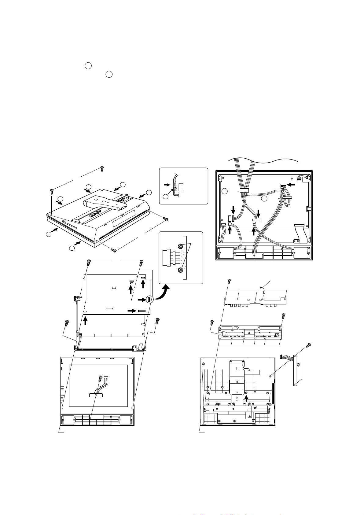
4. DISASSEMBLY OF THE SET
1. Remove four screws (1).
2. Opening six claws ( a ), release the cabinet B.
Remove the wire holder ( b ) and disconnect each
connectors (2~6).
Remove the cabinet B.
3. Remove two screws (7) which mounting the LCD
display unit.
4. Remove soldering of copper-foil tape (8) .
5. Disconnect each connectors (9~e) from the LCD
display unit.
6. Remove the cabinet A.
7. Remove four screws (r) which mounting the main
PWB unit.
8. Remove one screw (t) and remove the remote control
receptor PWB.
9. Remove five screws (y) and GND cable.
10.Remove ten screws (u) and remove the terminal
cover.
11.Remove two screws (i) and remove the switch PWB.
7
LC-121M2U
LC-150M2U
LC-121M2U
LC-150M2U
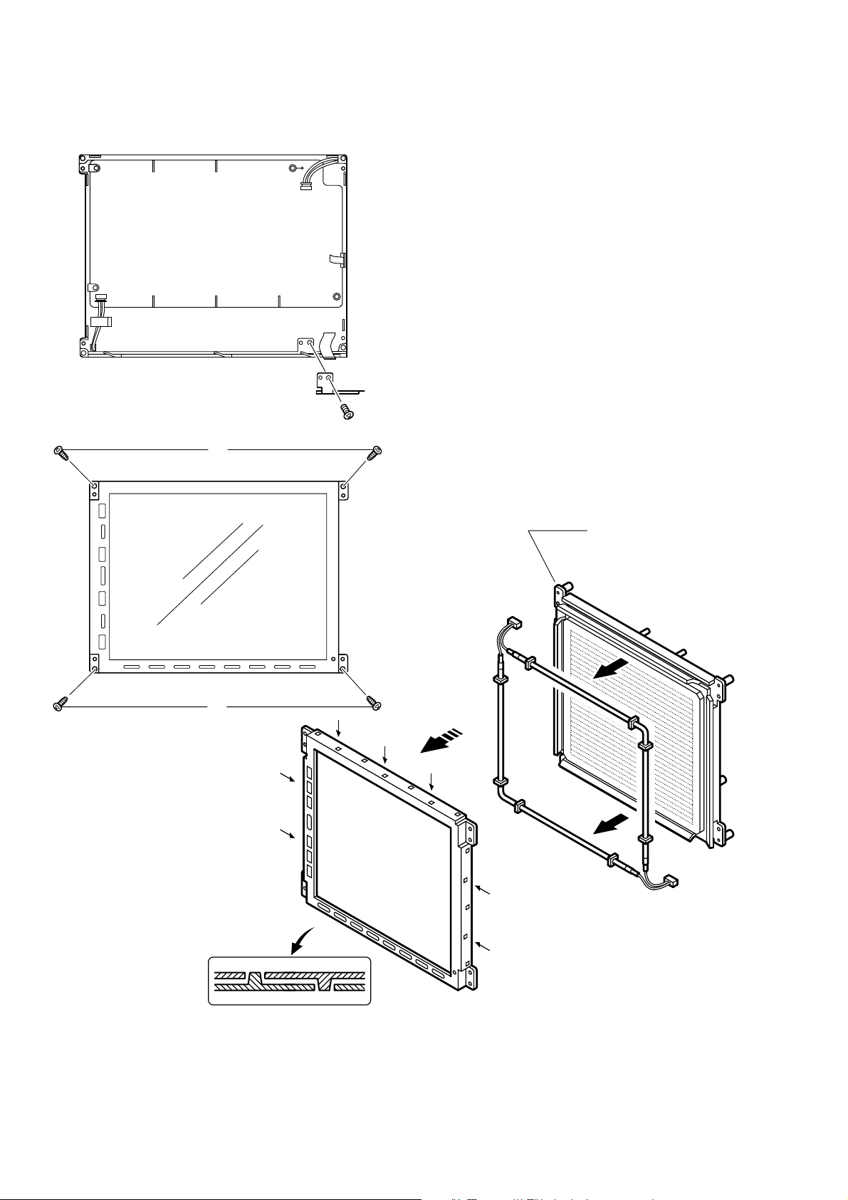
12.Remove one screw (o) and remove the SOS shield
angle.
13. Remove four screws (p) which mounting the LCD
display unit.
14.Spread bites of the LCD unit (a) out to be off from
claws.
15.Remove the Lamp unit (s).
o
Holder
LHLDZ2082CEKZ (LC-121M2U)
LHLDZ2085CEKZ (LC-150M2U)
p
p
a
s

8
LC-121M2U
LC-150M2U
LC-121M2U
LC-150M2U
The best adjustment is made before shipping. If any position deviation is found or after part replace is performed, adjust
as follows.
5-1. Preparation for adjustment
(1)Use the exclusive-use AC adapter or stable DC power supply.
AC adapter: UADP-0183CEZZ
DC power supply: 12 ± 0.5V
5-2. Special mode setting procedure
(1)After initialization of E
2
PROM the mode is changed to the adjustment mode.
[Procedure]
Connect TP2007 and TP2008 to GND, and turn on the power.
[Description]
• The initialization of microcomputer is as follows.
• AV position, DAC data, G/A data, and video chroma data adjustment values are taken as defaults.
(2)Change to adjustment mode
[Procedure]
Short-circuit TP2007 to GND, and turn on the power.
Or short-circuit TP2008 to GND, and turn on the power.
Or holding down the [AV INPUT] key and [MENU] key, turn on the main power, and simultaneously press the (inspection
process) [SELECT "] key and [VOL– ] key to change the mode to the adjustment mode.
[Description]
The manual adjustment or adjustment through communication with the automatic machine is performed.
(3)Inspection mode
[Procedure]
Holding down the [AV INPUT] key and [MENU] key, turn on the power.
[Description]
• In the ordinary menu select “PICTURE” with the [SELECT] key, and decide with the [VOL] key. Then select
“CONTRAST”, “TINT (only NTSC)”, “COLOR”, “BLACK LEVEL”, “SHARPNESS”, “RED” , and “BLUE” with the
[SELECT] key, and decide with the [VOL] key. After that, adjust values with the [VOL] key.
• In the ordinary menu select “SOUND” with the [SELECT] key, and decide with the [VOL] key. Then, select “TREBLE”,
“BASS”, and “BALANCE” with the [SELECT] key, and decide with the [VOL] key. After that adjust values with the [VOL]
key.
• VOLUME, CONTRAST, TINT (only NTSC), COLOR, BLACK LEVEL, SHARPNESS, RED, BLUE, TREBLE, BASS,
and BALANCE change as follows.
(4)Shipping setting mode
[Procedure]
Holding down the [AV INPUT] key and [MENU] key, turn on the main power, and simultaneously press the (inspection
process) [SELECT '] key and [VOL+] key to change the mode to the adjustment mode.
[Description]
User adjustment and other values are taken as defaults.
If AV1 is indicated as SETTING COMPLETE, setting has been completed.
ûMin.Û ûCenterÛ ûMax.Û
5. ADJUSTING PROCEDURE OF EACH SECTION

9
LC-121M2U
LC-150M2U
LC-121M2U
LC-150M2U
5-3. Cancel of special mode
Turn off the main unit power.
5-4. Preparation adjustment
(1)Use the exclusive-use AC adapter or stable DC power supply.
AC adapter: UADP-0183CEZZ
DC power supply: 12 ± 0.5V
5-5. OSD menu indication and items in case of manual adjustment
Adjusting range
Page Item Minimum Maximum Initial Remarks
1 + B – ADJ 0 255 128
MODEL M2H F2/M2H/M2U/M2E
TUNER OFF 1/2/OFF
AUDIO MULTIPLEX OFF OFF/ON
BOOSTER 0 0/1/2/3
SYSTEM AUTO N358/N443/PAL/PAL-M/SECAM/AUTO
COPY GUARD ON OFF/ON
CH MEMORY OFF OFF/12/16
SECAM ON OFF/ON
MULTI LANG. OFF OFF/ON
TIMER OFF OFF/ON
The Ver. No. will be displayed on the lowest part of lines.
2 TA1276 DATA ~~~~
COM 0 255 128
NTSC/PALM OSC 0 255 128
N358 BRIGHTNESS 0 255 170
R CUTOFF 0 255 80
B CUTOFF 0 255 80
N358UNICOLOR 0 127 80
R DRIVE 0 127 64
B DRIVE 0 127 64
N358SCOLOR 0 31 25
N358TINT 0 127 74
DATA COPY WAIT WAIT/SEND
3 N358 R-Y PHASE 0 3 2
N358 B-Y PHASE 0 3 1
N443 BRIGHTNESS 0 255 170
N443 UNICOLOR 0 127 80
N443 SCOLOR 0 31 25
N443TINT 0 127 74
PAL-M BRIGHTNESS 0 255 170
PAL-M UNICOLOR 0 127 80
PAL-M SCOLOR 0 31 25
PAL-M TINT 0 127 74
R-ADJ 0 255 128
One blank line.

10
LC-121M2U
LC-150M2U
LC-121M2U
LC-150M2U
4 PAL/SECAM OSC 0 255 128
PAL BRIGHTNESS 0 255 170
PAL UNICOLOR 0 127 80
PAL SCOLOR 0 31 25
PAL TINT 0 127 74
BELL F0 0 255 120
B-Y BLACK LEVEL 0 15 8
R-Y BLACK LEVEL 0 15 8
SECAM BRIGHTNESS 0 255 170
SECAM UNICOLOR 0 127 80
SECAM COLOR 0 127 75
SECAM TINT 0 127 74
5 DVD NT BRIGHTNESS 0 255 170
DVD NT UNICOLOR 0 127 80
DVD NT COLOR 0 127 75
DVD NT TINT 0 127 74
DVD NT R-YPHASE 0 3 2
DVD NT B-YPHASE 0 3 3
DVD PAL BRIGHTNESS
0 255 170
DVD PAL UNICOLOR 0 127 80
DVD PAL COLOR 0 127 75
DVD PAL TINT 0 127 74
I
2
C DATA 000000
I
2
C DATA WAIT WAIT/SEND
6 TEST PATTERN OFF ON/OFF
G/A DATA 0000
G/A DATA WAIT WAIT/SEND
DIGITAL SYNC SEP. 0 FF 87 Fixed
AV NTSC H 0 7F 18 Fixed
DVD NTSC H 0 7F 1C Fixed
AV PAL H 0 7F 11 Fixed
DVD PAL H 0 7F 15 Fixed
AV SECAM H 0 7F 0E Fixed
NT/PALM V 1 1F 0C Fixed
PAL V 1 1F 0B Fixed
SECAM V 1 1F 0B Fixed
7 N443 R-YPHASE 0 3 2 Fixed
N443 B-YPHASE 0 3 1 Fixed
PAL R-YPHASE 0 3 2 Fixed
PAL B-YPHASE 0 3 1 Fixed
PAL-M R-YPHASE 0 3 2 Fixed
PAL-M B-YPHASE 0 3 1 Fixed
SECAM R-YPHASE 0 3 2 Fixed
SECAM B-YPHASE 0 3 1 Fixed
DVD PAL R-YPHASE 0 3 2 Fixed
DVD PAL B-YPHASE 0 3 1 Fixed
COLOR 0 127 60 Fixed
SCONT 0 31 18 Fixed

11
LC-121M2U
LC-150M2U
LC-121M2U
LC-150M2U
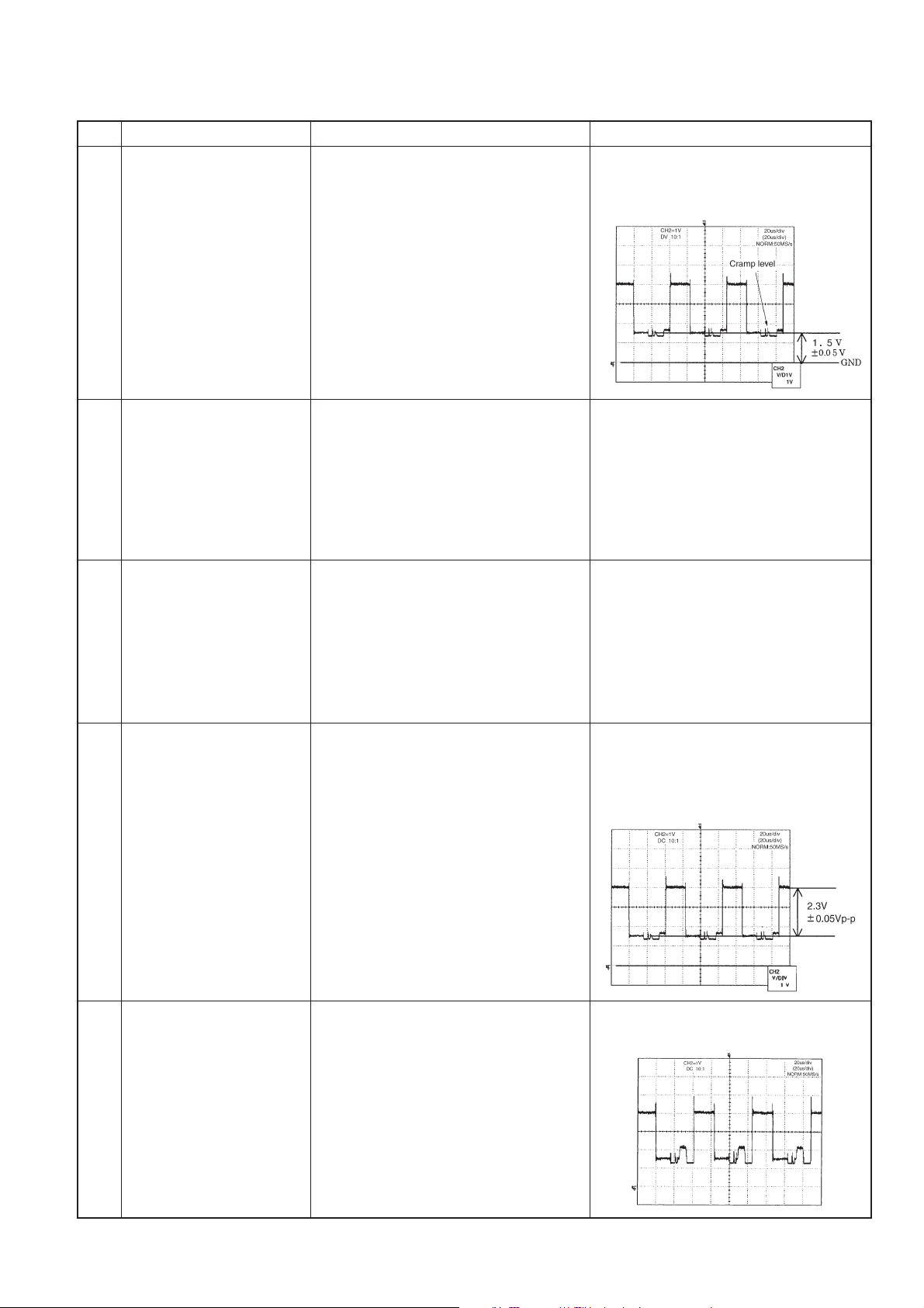
5-6. Service Adjusting
5-6-1. Basic Adjustment
Adjustment Adjusting conditions Adjusting method
1 +B Adjustment 1. Connect the DC voltmeter to 1. Adjust +B-ADJ to 5.1V ± 0.05V.
TP1104 ( DAC 9ch )
2 Model setup 1. Select the model "M2U". When M2U is selected, the item
settings are as follows.
TUNER OFF
AUDIO MULTIPLEX OFF
BOOSTER 0
SYSTEM AUTO
COPY GUARD ON
CH MEMORY OFF
SECAM ON
MULTI LANG. OFF
TIMER OFF
3 Counter-bias adjustment 1. Set the AV1 mode to set signal 1. Adjust COM so as to minimize the
noninput state. waveform peak-peak.
2. Fit the specified adjusting instrument (DAC7ch)
to the screen center.
3. Observe the adjusting instrument
output on the oscilloscope.
4 NTSC / PAL-MOSC 1. Input the monoscope pattern of 1. Adjust NTSC/PALM OSC so as to
adjustment NTSC into AV1. get the normal screen.
(DAC8ch)
8 DAC 2 1ch 0 255 0 Fixed
DAC 2 2ch 0 255 0 Fixed
DAC 2 3ch 0 255 0 Fixed
DAC 2 4ch 0 255 0 Fixed
DAC 2 5ch 0 255 0 Fixed
DAC 2 6ch 0 255 0 Fixed
DAC 2 7ch 0 255 0 Fixed
DAC 2 8ch 0 255 0 Fixed
DAC 2 9ch 0 255 0 Fixed
DAC 2 10ch 0 255 0 Fixed
DAC 2 11ch 0 255 0 Fixed
DAC 2 12ch 0 255 0 Fixed
12
LC-121M2U
LC-150M2U
LC-121M2U
LC-150M2U
5-6-2. AV input Adjustment
Adjustment Adjustment conditions Adjustment method
1 Brightness adjustment 1. Input the standard color bar signal 1. Adjust N358 BRIGHTNESS, and
(N358) (the same pattern as that of JPN-8CH) adjust the black level of G output so
of N358 into AV1. as to get DC 1.5±0.05V.
2. Connect the oscilloscope to TP821
(IC803, pin7, G output).
2 R-cut off adjustment 1. Input the standard color bar signal 1. Adjust R CUTOFF so as to equalize
(the same pattern as that of JPN-8CH) the black levels of green and red.
of N358 into AV1.
2. Connect the oscilloscope to TP821
(IC803, pin7, G output).
3. Connect the oscilloscope to TP819
(IC803, pin1, R output).
3 B-cut off adjustment 1. Input the standard color bar signal 1. Adjust B CUTOFF so as to equalize
(the same pattern as that of JPN-8CH) the black levels of green and blue.
of N358 into AV1.
2. Connect the oscilloscope to TP821
(IC803, pin7, G output).
3. Connect the oscilloscope to TP820
(IC803, pin8, B output).
4 Unicolor adjustment 1. Input the standard color bar signal 1. Adjust N358UNICOLOR, and
(N358) (the same pattern as that of JPN- adjust so as to get 100% white-
8CH) of N358 into AV1. black level video component equal
2. Connect the oscilloscope to TP821 to 2.3±0.05Vp-p.
(IC803, pin7, G output).
5 R DRIVE adjustment 1. Input the standard color bar signal 1. Adjust so as to get 100% white level
(the same pattern as that of JPN- identical with that of green.
8CH) of N358 into AV1.
2. Connect CH1 of oscilloscope to
TP821 (G output).
3. Connect CH2 of oscilloscope to
TP819 (R output).
13
LC-121M2U
LC-150M2U
LC-121M2U
LC-150M2U
6 B DRIVE adjustment 1. Input the standard color bar signal 1. Adjust so as to get 100% white level
(the same pattern as that of JPN- identical with that of green.
8CH) of N358 into AV1.
2. Connect CH1 of oscilloscope to
TP821 (G output).
3. Connect CH2 of oscilloscope to
TP820 (B output).
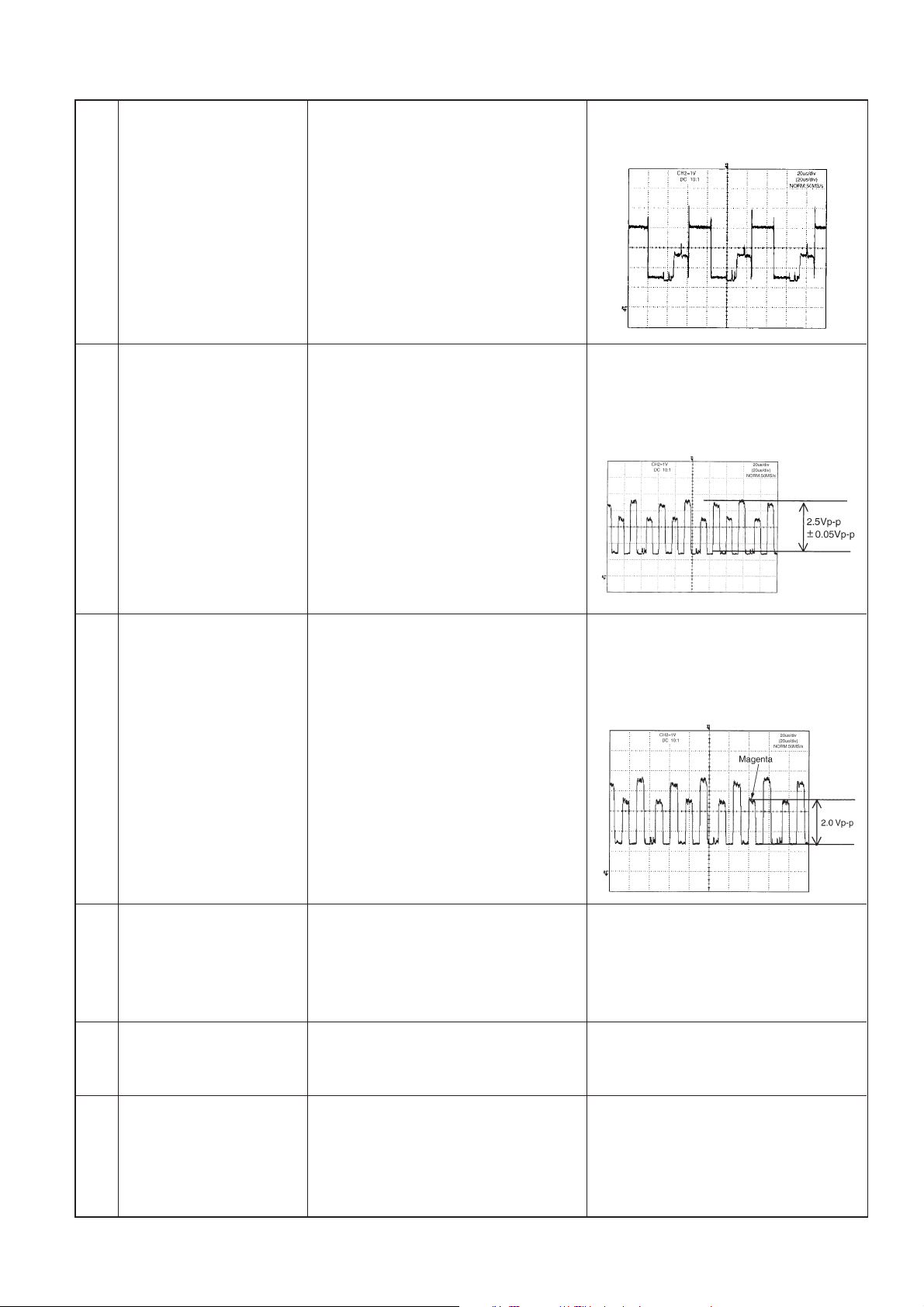
7 Color level adjustment 1. Input the standard color bar signal Adjust N358 SCOLOR so as to get the
(N358) (the same pattern as that of JPN- color bar signal blue amplitude
8CH) of N358 into AV1. (black level - peak level) equal to 2.5V
2. Connect the oscilloscope to TP820 ± 0.05Vp-p.
(B output).
8 Tint adjustment 1. Input the standard color bar signal 1. Adjust N358 TINT so as to get the
(N358) (the same pattern as that of JPN- color bar signal magenta amplitude
8CH) of N358 into AV1. (black level-peak level) equal to 2.0
2. Connect the oscilloscope to TP820 ± 0.05Vp-p.
(B output).
9 N443/PAL-M adjustment 1. Position the cursor on DATA COPY 1. The indication changes from WAIT
and press VOL key. to SEND, and after the lapse of one
second WAIT is restored. Thus, N443,
PAL-M adjustment is completed.
10 4V adjustment 1. Connect the DC voltmeter to TP1110 1. Adjust R-ADJ to 4.0V ± 0.05V.
( DAC 6ch )
11 PAL/SECAM OSC 1. Input the monoscope pattern of PAL 1. Adjust PAL/SECAM OSC so as to
adjustment into AV1. get the normal screen.
(DAC8ch)

14
LC-121M2U
LC-150M2U
LC-121M2U
LC-150M2U
12 Brightness adjustment 1. Input the standard color bar signal 1. Adjust PAL BRIGHTNESS, and
(PAL) of PAL into AV1. adjust the black level of G output
2. Connect oscilloscope to TP821 so as to get DC 1.5 ±0.05V.
(IC803, pin7, G output).
13 Unicolor adjustment 1. Input the standard color bar signal 1. Adjust PAL UNICOLOR, and adjust
(PAL) of PAL into AV1. so as to get 100% white-black level
2. Connect oscilloscope to TP821 video component equal to 2.3±0.05
(IC803, pin7 , G output ). Vp-p.
14 Color level adjustment 1. Input the standard color bar signal Adjust PAL SCOLOR so as to get the
(PAL) (the same pattern as that of E-12CH) color bar signal blue amplitude
of PAL into AV1. (black level - peak level) equal to 2.5V
2. Connect the oscilloscope to TP820 ±0.05Vp-p.
(B output).
15 Tint adjustment 1. Input the standard color bar signal 1. Adjust PAL TINT so as to get the color
(PAL) (the same pattern as that of E-12CH) bar signal magenta amplitude (black
of PAL into AV1. level-peak level) equal to 2.0±
2. Connect the oscilloscope to TP820 0.05Vp-p.
(B output).

15
LC-121M2U
LC-150M2U
LC-121M2U
LC-150M2U
16 BELL f0 adjustment 1. Connect the oscilloscope to 1. Adjust BELL f0 so as to minimize the
TP2851. a-level.
17 Brightness adjustment 1. Input the standard color bar signal 1. Adjust SECAM BRIGHTNESS, and
(SECAM) (the same pattern as that of E-10CH) adjust the black level of G output to
of SECAM into AV1. DC 1.5±0.05V.
2. Connect oscilloscope to TP821
(IC803, pin7, G output).
18 Unicolor adjustment 1. Input the standard color bar signal 1. Adjust SECAM UNICOLOR, and
(SECAM) (the same pattern as that of E-10CH) adjust so as to get 100% white-black
of SECAM into AV1. level video component equal to 2.3±
2. Connect oscilloscope to TP821 0.05Vp-p.
(IC803, pin7, G output ).
19 Color level adjustment 1. Input the standard color bar signal Adjust SECAM COLOR so as to get
(SECAM) (the same pattern as that of E-10CH) the color bar signal blue amplitude
of SECAM into AV1. (black level - peak level) equal to 2.5V
2. Connect the oscilloscope to TP820 ±0.05Vp-p.
(B output).
20 Tint adjustment 1. Input the standard color bar signal 1. Adjust SECAM TINT so as to get
(SECAM) (the same pattern as that of E-10CH) the color bar signal magenta amplitude
of SECAM into AV1. (black level - peak level) equal to 2.0V
2. Connect the oscilloscope to TP820 ±0.05Vp-p.
(B output).

16
LC-121M2U
LC-150M2U
LC-121M2U
LC-150M2U
5-6-3. Component input Adjustment
Adjustment Adjusting conditions Adjusting method
1 Brightness adjustment 1. From SG, input the 100% white color Adjust DVD NT BRIGHTNESS, and
(NTSC) bar signal of NTSC into conponent adjust the black level of G output so
terminal. as to get DC 1.5±0.05V.
2. Connect oscilloscope to TP821
(IC803, pin7, G output).
2 Unicolor adjustment 1. From SG, input the 100% white color Adjust DVD NT UNICOLOR, and
(NTSC) bar signal of NTSC into conponent adjust so as to get 100% white-
terminal. black level video component equal
2. Connect oscilloscope to TP820 to 2.3±0.05Vp-p.
(IC803, pin8).
3 Color level adjustment 1. From SG, input the 100% white color Adjust DVD NT COLOR so as to get
(NTSC) bar signal of NTSC into conponent the color bar signal blue amplitude
terminal. (black level - peak level) equal to
2. Connect the oscilloscope to TP820 2.8V±0.05Vp-p.
(B output).
4 Tint adjustment 1. From SG, input the 100% white color Adjust DVD NT TINT so as to get the
(NTSC) bar signal of NTSC into conponent color bar signal magenta amplitude
terminal. (black level - peak level) equal to 2.3V
2. Connect the oscilloscope to TP820 ±0.05Vp-p.
(B output).

17
LC-121M2U
LC-150M2U
LC-121M2U
LC-150M2U
5 Brightness adjustment 1. From SG, input the 100% white color Adjust DVD PAL BRIGHTNESS, and
(PAL) bar signal of PAL into conponent adjust the black level of G output so
terminal. as to get DC 1.5±0.05V.
2. Connect oscilloscope to TP821
(IC803, pin7, G output).
6 Unicolor adjustment 1. From SG, input the 100% white color Adjust DVD PAL UNICOLOR, and
(PAL) bar signal of PAL into conponent adjust so as to get 100% white-
terminal. black level video component equal
2. Connect oscilloscope to TP820 to 2.3±0.05Vp-p.
(IC803, pin8, B output).
7 Color level adjustment 1. From SG, input the 100% white color Adjust DVD PAL COLOR so as to get
(PAL) bar signal of PAL into conponent the color bar signal blue amplitude
terminal. (black level - peak level) equal to
2. Connect the oscilloscope to TP820 2.8V±0.05Vp-p.
(B output).
8 Tint adjustment 1. From SG, input the 100% white color Adjust DVD PAL TINT so as to get
(PAL) bar signal of PAL into conponent the color bar signal magenta amplitude
terminal. (black level - peak level) equal to
2. Connect the oscilloscope to TP820 2.3V±0.05Vp-p.
(B output).
9 Tint adjustment Position the cursor on N358 TINT. Lower unconditionally the value by
10 points.

18
LC-121M2U
LC-150M2U
LC-121M2U
LC-150M2U
5-7. Shipping setting
(1)[Procedure]
Holding down the [AV INPUT] key and [MENU] key, turn on the main power, and simultaneously press the (inspection
process) [SELECT '] key and [VOL+] key to change the mode to the adjustment mode.
(2)[Indication]
AV1 is indicated as SETTING COMPLETE.
(3)[Description]
Mode is memorized as SETTING COMPLETE.
Menu setting descriptions are as follows.
VOLUME 30
CONTRAST 30 (AV1 / AV2 / COMPONENT)
TINT 0 (AV1 / AV2 / COMPONENT) (ONLY NTSC)
COLOR 0 (AV1 / AV2 / COMPONENT)
SHARPNESS 0 (AV1 / AV2 / COMPONENT)
RED 0 (AV1 / AV2 / COMPONENT)
BLUE 0 (AV1 / AV2 / COMPONENT)
COLOR SYSTEM AUTO (AV1 / AV2 / COMPONENT)
TREBLE 0
BASS 0
BALANCE 0
BRIGHTNESS BRIGHT
UPSIDE NORMAL
RIGHT / LEFT NORMAL
AV2 IN / OUT IN
AV1
SETTING COMPLETE
 Loading...