


TopPage
LC-60LE635E(B),RU(B)/636E(B),S(B)/638E(B)
SERVICE MANUAL
No. S82X760LE635B
LCD COLOUR TELEVISION
LC-60LE635E(B)/RU(B)
LC-60LE636E(B)/S(B)
MODELS LC-60LE638E(B)
In the interests of user-safety (Required by safety regulations in some countries) the set should be restored to its orig- inal condition and only parts identical to those specified should be used.
OUTLINE
This model is based on the LC-60LE830E and partially modified.
For the contents not covered in this Service Manual, accordingly, please refer to the LC-60LE830E (S81T252LE830E) Service Manual.
CONTENTS
OUTLINE AND DIFFERENCES FROM BASE MODEL
|
OUTLINE............................................................. |
i |
|
DIFFERENCES FROM BASE MODEL............... |
i |
SAFETY PRECAUTION |
|
|
|
IMPORTANT SERVICE SAFETY PRE- |
|
|
CAUTION ........................................................ |
xiii |
|
PRECAUTIONS A PRENDRE LORS DE |
|
|
LA REPARATION............................................ |
xiv |
|
PRECAUTIONS FOR USING LEAD-FREE |
|
|
SOLDER .......................................................... |
xv |
CHAPTER 1. OPERATION MANUAL |
|
|
[1] |
Parts Name .................................................... |
1-1 |
[2] |
OPERATION MANUAL .................................. |
1-7 |
CHAPTER 2. SPECIFICATIONS |
|
|
[1] |
SPECIFICATIONS ......................................... |
2-1 |
CHAPTER 3. DIMENSIONS |
|
|
[1] |
DIMENSIONS ................................................ |
3-1 |
CHAPTER 4. REMOVING OF MAJOR PARTS |
|
|
[1] REMOVING OF MAJOR PARTS ................... |
4-1 |
|
[2]The location putting on the heat measure
sheet .............................................................. |
4-7 |
[3] Precautions for assembly............................... |
4-9 |
CHAPTER 5. ADJUSTMENT |
|
|
[1] |
ADJUSTMENT PROCEDURE ...................... |
5-1 |
CHAPTER 6. TROUBLESHOOTING TABLE |
|
|
[1] |
TROUBLESHOOTING TABLE ...................... |
6-1 |
[2]LED flashing specification at the time of the
error ............................................................... |
6-7 |
CHAPTER 7. MAJOR IC INFORMATIONS |
|
[1] MAJOR IC INFORMATIONS ......................... |
7-1 |
CHAPTER 8. OVERALL WIRING/SYSTEM BLOCK DIAGRAM
[1]OVERALL WIRING DIAGRAM (LC-
60LE635E,RU/638E) ..................................... |
8-1 |
[2]OVERALL WIRING DIAGRAM (LC-
60LE636E/S) ................................................. |
8-2 |
[3]SYSTEM BLOCK DIAGRAM (LC-
60LE635E,RU/638E) ..................................... |
8-3 |
[4]SYSTEM BLOCK DIAGRAM (LC-
60LE636E/S) ................................................. |
8-4 |
Parts Guide
Parts marked with "  " are important for maintaining the safety of the set. Be sure to replace these parts with specified ones for maintaining the safety and performance of the set.
This document has been published to be used for after sales service only.
The contents are subject to change without notice.
LC-60LE635E(B),RU(B)/636E(B),S(B)/638E(B)
OUTLINE AND DIFFERENCES FROM BASE MODEL
OUTLINE
This model is based on the LC-60LE830E and partially modified.
For the contents not covered in this Service Manual, accordingly, please refer to the LC-60LE830E (S81T252LE830E) Service Manual.
DIFFERENCES FROM BASE MODEL
Ref |
Description |
LC-60LE830E |
LC-60LE635E(B) |
LC-60LE638E(B) |
LC-60LE636E(B) |
Inter- |
Note |
|
No. |
|
(S81T252LE830E) |
LC-60LE635RU(B) |
|
LC-60LE636S(B) |
chang |
|
|
|
|
|
|
|
|
eabil- |
|
|
|
|
|
|
|
|
ity |
|
|
PRINTED WIRING BOARD ASSEMBLIES |
|
|
|
|
|
|||
N |
MAIN Unit |
DKEYDF733FM51 |
DKEYDF733FM55 |
DKEYDF733FM57 |
DKEYDF733FM56 |
D |
Chanded |
|
N |
R/C OPC Unit |
DUNTKF494FM02 |
DUNTKF494FM06 |
← |
← |
- |
Changed |
|
|
|
|
|
|
|
|
|
|
N |
ICON Unit |
DUNTKF770FM51 |
DUNTKF770FM53 |
DUNTKF770FM53 |
DUNTKF770FM53 |
D |
Chanded |
|
N |
TOUCH SENSOR Unit |
RUNTKA869WJQ |
- |
- |
- |
- |
Delete |
|
Z |
||||||||
|
|
|
|
|
|
|
||
N |
3D IR TRANSMITTER Unit |
RUNTKA819WJQ |
- |
- |
- |
- |
Delete |
|
Z |
||||||||
|
|
|
|
|
|
|
||
N |
POWER Unit |
RUNTKA799WJN1 |
RUNTKA932WJQZ |
← |
← |
D |
Chanded |
|
N |
LCD CONTRL Unit |
RUNTK4909TPYN |
DUNTKF778FM53 |
← |
← |
D |
Chanded |
|
N |
KEY Unit |
- |
DUNTKF800FM52 |
DUNTKF800FM52 |
DUNTKF800FM52 |
- |
Add |
|
LCD Panel Module |
|
|
|
|
|
|
||
N |
60" LCD Panel Module Unit |
R1LK600D3GW4BH |
R1LK600D3GV0AY |
← |
← |
D |
Chanded |
|
|
|
|
|
|
|
|
|
|
|
|
|
|
|
|
|
||
CABINET AND MECHANICAL PARTS |
|
|
|
|
|
|
||
|
Please refer to a Parts Guide. |
|
|
|
|
|
|
|
SUPPLIED ACCESSORIES/PACKING PARTS (NOT REPLACEMENT ITEM)
Please refer to a Parts Guide.
SERVICE JIG (USE FOR SERVICING)
Please refer to a Parts Guide.
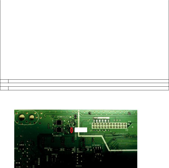
Note In the case of changing the MAIN Unit ( DKEYDF733FM55/56/57) *Please confirm that following part (R9682) is added in this unit
R9682
i

LC-60LE635E(B),RU(B)/636E(B),S(B)/638E(B)
LC60LE635E |
Service Manual |
SAFETY PRECAUTION |
IMPORTANT SERVICE SAFETY PRECAUTION

 Service work should be performed only by qualified service technicians who are thoroughly familiar with all safety checks and the servicing guidelines which follow:

 WARNING
1.For continued safety, no modification of any circuit should be attempted.
2.Disconnect AC power before servicing.
CAUTION: FOR CONTINUED PROTECTION AGAINST A RISK OF FIRE REPLACE ONLY WITH SAME TYPE FUSE.
F7001 (250V 5A)
 BEFORE RETURNING THE RECEIVER (Fire & Shock Hazard)
Before returning the receiver to the user, perform the following safety checks:
3.Inspect all lead dress to make certain that leads are not pinched, and check that hardware is not lodged between the chassis and other metal parts in the receiver.
4.Inspect all protective devices such as non-metallic control knobs, insulation materials, cabinet backs, adjustment and compartment covers or shields, isolation resistor-capacitor networks, mechanical insulators, etc.
•Use an AC voltmeter having with 5000 ohm per volt, or higher, sensitivity or measure the AC voltage drop across the resistor.
•Connect the resistor connection to all exposed metal parts having a return to the chassis (antenna, metal cabinet, screw heads, knobs and control shafts, escutcheon, etc.) and measure the AC voltage drop across the resistor.
All checks must be repeated with the AC cord plug connection reversed. (If necessary, a nonpolarized adaptor plug must be used only for the purpose of completing these checks.)
Any reading of 0.75 Vrms (this corresponds to 0.5 mA rms AC.) or more is excessive and indicates a potential shock hazard which must be corrected before returning the monitor to the owner.
DVM
AC SCALE
1.5k ohm
10W
0.15 µF
TEST PROBE
5.To be sure that no shock hazard exists, check for leakage current in the following manner.
•Plug the AC cord directly into a 220-240 volt AC outlet.
•Using two clip leads, connect a 1.5k ohm, 10 watt resistor paralleled by a 0.15?F capacitor in series with all exposed metal cabinet parts and a known earth ground, such as electrical conduit or electrical ground connected to an earth ground.
TO EXPOSED |
CONNECT TO |
METAL PARTS |
KNOWN EARTH |
|
GROUND |
///////////////////////////////////////////////////////////////////////////////////////////////////////////////////////////////////////////////////////////////////////////////////////////////////////////////////////////////////////////
SAFETY NOTICE
Many electrical and mechanical parts in LCD color television have special safety-related characteristics.
These characteristics are often not evident from visual inspection, nor can protection afforded by them be necessarily increased by using replacement components rated for higher voltage, wattage, etc.
Replacement parts which have these special safety characteristics are identified in this manual; electrical components having such features
are identified by " " and shaded areas in the Replacement Parts List and Schematic Diagrams.
For continued protection, replacement parts must be identical to those used in the original circuit.
The use of a substitute replacement parts which do not have the same safety characteristics as the factory recommended replacement parts shown in this service manual, may create shock, fire or other hazards.
///////////////////////////////////////////////////////////////////////////////////////////////////////////////////////////////////////////////////////////////////////////////////////////////////////////////////////////////////////////
xiii

LC-60LE635E(B),RU(B)/636E(B),S(B)/638E(B)
PRECAUTIONS A PRENDRE LORS DE LA REPARATION
 Ne peut effectuer la réparation qu' un technicien spécialisé qui s'est parfaitement accoutumé à toute vérification de sécurité et aux conseils suivants.
 AVERTISSEMENT
1.N'entreprendre aucune modification de tout circuit. C'est dangereux.
2.Débrancher le récepteur avant toute réparation.
CAUTION: FOR CONTINUED PROTECTION AGAINST A RISK OF FIRE REPLACE ONLY WITH SAME TYPE FUSE.
F7001 (250V 5A)
 VERIFICATIONS CONTRE L'INCEN-DIE ET LE CHOC ELECTRIQUE
Avant de rendre le récepteur à l'utilisateur, effectuer les vérifications suivantes.
3.Inspecter tous les faisceaux de câbles pour s'assurer que les fils ne soient pas pincés ou qu'un outil ne soit pas placé entre le châssis et les autres pièces métalliques du récepteur.
4.Inspecter tous les dispositifs de protection comme les boutons de commande non-métalliques, les isolants, le dos du coffret, les couvercles ou blindages de réglage et de compartiment, les réseaux de résistancecapacité, les isolateurs mécaniques, etc.
5.S'assurer qu'il n'y ait pas de danger d'électrocution en vérifiant la fuite de courant, de la facon suivante:
•Brancher le cordon d'alimentation directem-ent à une prise de courant de 220-240V. (Ne pas utiliser de transformateur d'isolation pour cet essai).
•A l'aide de deux fils à pinces, brancher une résistance de 1.5 kΩ 10 watts en parallèle avec un condensateur de 0.15µF en série avec toutes les pièces métalliques exposées du coffret et une terre connue comme une conduite électrique ou une prise de terre branchée à la terre.
•Utiliser un voltmètre CA d'une sensibilité d'au moins 5000Ω/V pour mesurer la chute de tension en travers de la résistance.
•Toucher avec la sonde d'essai les pièces métalliques exposées qui présentent une voie de retour au châssis (antenne, coffret métallique, tête des vis, arbres de commande et des boutons, écusson, etc.) et mesurer la chute de tension CA en-travers de la résistance. Toutes les vérifications doivent être refaites après avoir inversé la fiche du cordon d'alimentation. (Si nécessaire, une prise d'adpatation non polarisée peut être utilisée dans le but de terminer ces vérifications.)
La tension de pointe mesurèe ne doit pas dépasser 0.75V (correspondante au courant CA de pointe de 0.5mA).
Dans le cas contraire, il y a une possibilité de choc électrique qui doit être supprimée avant de rendre le récepteur au client.
DVM
 ECHELLE CA
1.5k ohm
10W
0.15 µF SONDE D'ESSAI
AUX PIECES |
BRANCHER A UNE |
|
METALLIQUES |
||
TERRE CONNUE |
||
EXPOSEES |
||
|
/////////////////////////////////////////////////////////////////////////////////////////////////////////////////////////////////////////////////////////////////////////////////////////////////////////////////////////////////////////////
AVIS POUR LA SECURITE
De nombreuses pièces, électriques et mécaniques, dans les téléviseur ACL présentent des caractéristiques spéciales relatives à la sécurité, qui ne sont souvent pas évidentes à vue. Le degré de protection ne peut pas être nécessairement augmentée en utilisant des pièces de remplacement étalonnées pour haute tension, puissance, etc.
Les pièces de remplacement qui présentent ces caractéristiques sont identifiées dans ce manuel; les pièces électriques qui présentent ces particularités sont identifiées par la marque "  " et hachurées dans la liste des pièces de remplacement et les diagrammes schématiques.
Pour assurer la protection, ces pièces doivent être identiques à celles utilisées dans le circuit d'origine. L'utilisation de pièces qui n'ont pas les mêmes caractéristiques que les pièces recommandées par l'usine, indiquées dans ce manuel, peut provoquer des électrocutions, incendies, radiations X ou autres accidents.
/////////////////////////////////////////////////////////////////////////////////////////////////////////////////////////////////////////////////////////////////////////////////////////////////////////////////////////////////////////////
xiv

LC-60LE635E(B),RU(B)/636E(B),S(B)/638E(B)
PRECAUTIONS FOR USING LEAD-FREE SOLDER

 Employing lead-free solder
•“PWBs” of this model employs lead-free solder. The LF symbol indicates lead-free solder, and is attached on the PWBs and service manuals. The alphabetical character following LF shows the type of lead-free solder.
Example:
|
|
|
|
|
|
|
|
|
|
|
|
|
|
|
|
|
|
|
|
|
|
|
|
Indicates lead-free solder of tin, silver and copper. |
Indicates lead-free solder of tin, silver and copper. |
||||||||||

 Using lead-free wire solder
•When fixing the PWB soldered with the lead-free solder, apply lead-free wire solder. Repairing with conventional lead wire solder may cause damage or accident due to cracks.
As the melting point of lead-free solder (Sn-Ag-Cu) is higher than the lead wire solder by 40 ?C, we recommend you to use a dedicated soldering bit, if you are not familiar with how to obtain lead-free wire solder or soldering bit, contact our service station or service branch in your area.

 Soldering
•As the melting point of lead-free solder (Sn-Ag-Cu) is about 220 ?C which is higher than the conventional lead solder by 40 ?C, and as it has poor solder wettability, you may be apt to keep the soldering bit in contact with the PWB for extended period of time. However, Since the land may be peeled off or the maximum heat-resistance temperature of parts may be exceeded, remove the bit from the PWB as soon as you confirm the steady soldering condition.
Lead-free solder contains more tin, and the end of the soldering bit may be easily corroded. Make sure to turn on and off the power of the bit as required.
If a different type of solder stays on the tip of the soldering bit, it is alloyed with lead-free solder. Clean the bit after every use of it. When the tip of the soldering bit is blackened during use, file it with steel wool or fine sandpaper.
•Be careful when replacing parts with polarity indication on the PWB silk.
Lead-free wire solder for servicing
PARTS CODE |
PRICE |
PART |
DESCRIPTION |
|
RANK |
DELIVERY |
|||
|
|
|||
ZHNDAi123250E |
BL |
J |
?0.3mm 250g (1roll) |
|
ZHNDAi126500E |
BK |
J |
?0.6mm 500g (1roll) |
|
ZHNDAi12801KE |
BM |
J |
?1.0mm 1kg (1roll) |
xv

LC-60LE635E(B),RU(B)/636E(B),S(B)/638E(B)
CHAPTER 1. OPERATION MANUAL |
Service Manual |
L 60LE635E |
|
[1] Parts Name
TV (front/side view)
Illumination LED
 P
P

OPC sensor
Remote control sensor
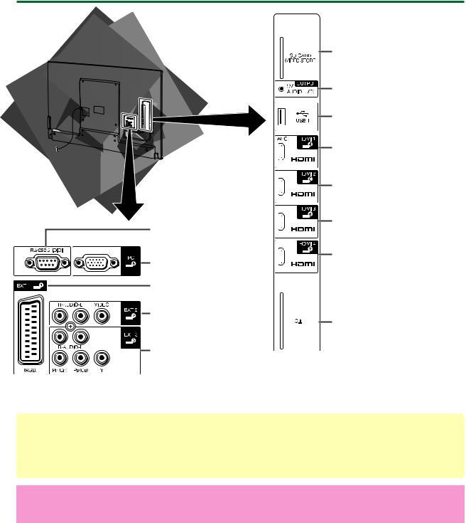
TV (rear view)
USB 3 ( WIRELESS LAN) port |
HDMI 2/PC AUDIO (L/R) |
USB 2 (HDD) port |
jack*1 |
|
ETHERNET (10/100) terminal |
|
|
|
|
|
DIGITAL AUDIO OUTPUT |
|
|
|
|
|
terminal |
|
|
|
|
|
|
|
|
Satellite antenna terminal |
|
|
|
Antenna terminal |
||
|
|
|||||
(635/638 series only) |
|
|
|
|
||
*1 The HDMI 2 and PC terminals can both use the same audio input terminal (HDMI 2/PC AUDIO (L/R)). However, the proper item must be selected in the “Audio select” menu.
1 – 1
LC-60LE635E(B),RU(B)/636E(B),S(B)/638E(B)
TV (rear view) — continued
|
SD CARD |
|
|
(VIDEO STORE) slot |
|
|
OUTPUT (Headphones/ |
|
|
AUDIO (L/R)) terminal*2 |
|
|
USB 1 port |
|
|
HDMI 1 |
(HDMI/ARC) |
|
terminal |
|
|
HDMI 2 |
(HDMI) terminal |
RS-232C terminal |
HDMI 3 |
(HDMI) terminal |
|
|
|
PC terminal |
HDMI 4 |
(HDMI) terminal |
|
|
|
EXT 1 (RGB) terminal |
|
|
EXT 2 (VIDEO/AUDIO |
C.I. (COMMON |
|
(L/R)) terminal |
||
|
INTERFACE) slot |
|
EXT 3 (Component/
AUDIO (L/R)) terminal
*2 When the headphone is connected to the OUTPUT terminal, the audio can be output from the speakers.
WARNING
 Excessive sound pressure from earphones and headphones can cause hearing loss.
 Do not set the volume at a high level. Hearing experts advise against extended listening at high volume levels.
Important information:
Satellite services are only available for the 635/638 model series.
1 – 2

LC-60LE635E(B),RU(B)/636E(B),S(B)/638E(B)
Remote control unit (LC-60LE635E(B),RU(B)/636E(B).S(B))
|
15 |
1 |
16 |
2 |
|
3 |
|
4 |
|
5 |
|
6 |
|
7 |
17 |
8 |
18 |
9 |
19 |
10 |
20 |
11 |
|
12 |
21 |
13 |
|
14 |
22 |
|
23 |
|
24 |
1
 (Standby/On)
2ATV
Access conventional analogue TV mode.
DTV
Access digital TV mode.
SAT
Access satellite mode.
RADIO
DTV/SAT: Switch between radio and data mode.
 When only data broadcasting (no radio broadcasting) is transmitted by DVB, the radio broadcasting will be skipped.
3AQUOS LINK buttons
4CONTROL
Display a panel to operate some functions on the screen.
NET: “NET MENU” screen on/off.
5TIME SHIFT (READY/ /
/  /
/  )
)
Temporarily record a programme you are watching.
6Numeric buttons 0_9
Set the channel. Enter desired numbers. Set the page in teletext mode.
 When the five Nordic countries (Sweden, Norway, Finland, Denmark or Iceland) are selected in the country setting from initial auto installation, DTV services are four digits.
When another country is selected, DTV services are three digits.
7 (Flashback)
Return to the previously selected channel or external input.
8  (Sound mode)
Select a sound multiplex mode.
(Wide mode)
Select a wide mode.
1 – 3
LC-60LE635E(B),RU(B)/636E(B),S(B)/638E(B)
9 (Mute)
TV sound on/off.
10 +/- (Volume)
Increase/decrease TV volume.
11MENU
“Menu” screen on/off.
12None
This button does not work on this model.
13 /
/ /
/ /
/  (Cursor)
Select a desired item.
OK
Execute a command.
ATV/DTV/SAT: Display “CH list” when no other “Menu” screen is running.
14END
ATV/DTV/SAT: Exit the “Menu” screen. NET: Return to the start page.
15NET
Access Net TV.
16 (Display information)
Display the station information (channel number, signal, etc.) on the screen.
P. INFO
Display programme information transmitted through digital video broadcasting (DTV/SAT only).
17 (INPUT)
Select an input source.
18AV MODE
Select audio/video settings.
ECO(Standard/Advanced/Off)
Select “Energy save” setting.
19 (Teletext)
ATV: Display analogue teletext. DTV/SAT: Select MHEG-5 or teletext for DTV/SAT.
20  /
/
ATV/DTV/SAT: Select the TV channel. NET: Scrolls pages up/down.
21EPG
DTV/SAT: Display the EPG screen.
22 (Return)
ATV/DTV/SAT: Return to the previous “Menu” screen.
NET: Return to the previous page (this may not function for some services).
23 Buttons for useful operations
(Subtitle)
Switch subtitle languages on/off.
(Reveal hidden teletext)
(Subpage)
(Freeze/Hold)
Freeze a moving image on the screen. Teletext: Stop updating teletext pages automatically or release the hold mode.
24R/G/Y/B (Colour) buttons
The coloured buttons are correspondingly used to select the coloured items on the screen (e.g., EPG, MHEG-5, teletext).
Important information:
Satellite services are only available for the 635 model series.
1 – 4

LC-60LE635E(B),RU(B)/636E(B),S(B)/638E(B)
Remote control unit (LC-60LE638E(B))
15 1 


 16 2
16 2 


 3
3 


4 5
6
1
 (Standby/On)
2ATV
Access conventional analogue TV mode.
DTV
Access digital TV mode.
SAT
Access satellite mode.
RADIO
DTV/SAT: Switch between radio and data mode.
 When only data broadcasting (no radio broadcasting) is transmitted by DVB, the radio broadcasting will be skipped.
7 |
17 |
8 |
18 |
9 |
19 |
10 |
20 |
11 |
|
12 |
21 |
13 |
|
14 |
22 |
|
23 |
|
24 |
3AQUOS LINK buttons
4CONTROL
Display a panel to operate some functions on the screen.
NET: “NET MENU” screen on/off.
5TIME SHIFT (READY/ /
/  /
/  )
)
Temporarily record a programme you are watching.
6Numeric buttons 0_9
Set the channel. Enter desired numbers. Set the page in teletext mode.
Inputting letters with the numeric buttons is only available with MHP services (Italy only).
 When the five Nordic countries (Sweden, Norway, Finland, Denmark or Iceland) are selected in the country setting from initial auto installation, DTV services are four digits.
When another country is selected, DTV services are three digits.
7 (Flashback)
Return to the previously selected channel or external input.
8  (Sound mode)
Select a sound multiplex mode.
(Wide mode)
Select a wide mode.
1 – 5
LC-60LE635E(B),RU(B)/636E(B),S(B)/638E(B)
9 (Mute)
TV sound on/off.
10 +/- (Volume)
Increase/decrease TV volume.
11MENU
“Menu” screen on/off.
12None
This button does not work on this model.
13 /
/  /
/  /
/  (Cursor)
Select a desired item.
OK
Execute a command.
ATV/DTV/SAT: Display “CH list” when no other “Menu” screen is running.
 “CH list” may not be displayed even by pressing OK when executing the MHP application. If so, you
can display “CH list” from “Menu” > “CH list”.
14END
ATV/DTV/SAT: Exit the “Menu” screen. NET: Return to the start page.
15NET
Access Net TV.
16 (Display information)
Display the station information (channel number, signal, etc.) on the screen.
P. INFO
Display programme information transmitted through digital video broadcasting (DTV/SAT only).
17  (INPUT)
Select an input source.
18APP
Display the MHP application list (Italy only).
ECO(Standard/Advanced/Off)
Select “Energy save” setting.
19(Teletext)
ATV: Display analogue teletext. DTV/SAT: Select teletext for DTV/SAT.
20P  /
/ 
ATV/DTV/SAT: Select the TV channel. NET: Scrolls pages up/down.
21EPG
DTV/SAT: Display the EPG screen.
22 (Return)
ATV/DTV/SAT: Return to the previous “Menu” screen.
NET: Return to the previous page (This may not function for some services).
23 Buttons for useful operations
 (Subtitle)
Switch subtitle languages on/off.
 (Reveal hidden teletext)
 (Subpage)
 (Freeze/Hold)
Freeze a moving image on the screen. Teletext: Stop updating teletext pages automatically or release the hold mode.
24R/G/Y/B (Colour) buttons
The coloured buttons are correspondingly used to select the coloured items on the screen (e.g., EPG, MHP, teletext).
1 – 6

[2] OPERATION MANUAL
Attaching the stand unit
 Before attaching (or detaching) the stand, unplug the AC cord.
 Before performing work, spread cushioning over the surface on which you will be laying the TV. This will prevent it from being damaged.
CAUTION
 Attach the stand in the correct direction.
  Be sure to follow the instructions. Incorrect
installation of the stand may result in the TV falling over .
1Confirm that there are twelve screws (eight long screws and four short screws) supplied with the stand unit.
21 Set the supporting post for the stand unit onto the polystyrene foam.
2Attach the stand base to the supporting post.
3Insert and tighten the eight screws into the eight holes on the bottom of the stand base.
 Hold the stand unit securely with one hand, and then tighten the screws.
Stand base |
|
|
|
|
|
Long screws |
||||
|
|
|
|
|
|
|
|
|
|
|
|
|
|
|
|
|
|
|
|
|
|
|
|
|
|
|
|
|
|
|
|
|
|
|
|
|
|
|
|
|
|
|
|
|
|
|
|
|
|
|
|
|
|
|
|
|
|
|
|
|
|
|
|
|
|
|
|
|
|
|
|
|
|
|
|
|
|
|
|
|
|
|
|
|
|
|
|
|
|
|
|
|
|
|
|
|
|
|
|
|
|
|
|
|
|
|
|
|
|
|
|
|
|
|
|
|
|
|
|
|
|
|
|
|
|
|
|
|
|
|
|
|
|
|
|
|
|
|
|
|
|
|
|
|
|
|
|
|
|
|
|
|
|
|
|
|
|
|
|
|
|
|
|
|
|
|
|
|
|
|
|
|
|
|
|
|
|
|
|
|
|
|
|
|
|
|
|
|
|
|
|
|
|
|
|
|
|
TV front
Supporting post
LC-60LE635E(B),RU(B)/636E(B),S(B)/638E(B)
3Insert the stand into the openings on the bottom of the TV (hold the stand so it will not drop from
the edge of the base area).
 Make sure that the stand is firmly inserted into the TV. Improper installation may result in tilting of the TV set.
Soft cushion
4Insert and tighten the four screws into the four holes on the rear of the TV.
Short screws
1 – 7

LC-60LE635E(B),RU(B)/636E(B),S(B)/638E(B)
CHAPTER 2. SPECIFICATIONS |
Service Manual |
||||
L 60LE635E |
|
|
|
|
|
[1] SPECIFICATIONS |
|
|
|
|
|
|
Specifications |
|
|
||
|
|
|
|
|
|
|
Item |
|
|
|
LCD COLOUR TV (60"/152 cm), |
|
|
|
|
|
LC-60LE635E(B) LC-60LE638E(B) |
|
|
|
|
|
LC-60LE635RU(B) |
|
|
|
|
|
LC-60LE636E(B) |
|
|
|
|
|
LC-60LE636S(B) |
|
LCD panel |
|
|
|
152 cm (60") X-Gen panel |
|
Resolution |
|
|
|
1,920 x 1,080 x 3 dots |
|
Video colour system |
|
PAL/SECAM/NTSC 3.58/NTSC 4.43/PAL 60 |
||
|
TV |
TV- |
|
Analogue |
CCIR (B/G, I, D/K, L/L’) |
|
function |
standard |
|
Digital |
DVB-T (2K/8K OFDM), DVB-C, DVB-S/S2 |
|
|
|
|
(635 series ) |
|
|
|
|
|
Digital |
DVB-T (2K/8K OFDM), |
|
|
|
|
(636 series ) |
DVB-T2 (1K/2K/4K/8K/16K/32K OFDM), DVB-C |
|
|
Receiving |
|
VHF/UHF |
IR A ch_E69 ch (Digital), E2_E69 ch, F2_F10 ch, |
|
|
channel |
|
|
I21_I69 ch, IR A_IR J ch |
|
|
|
|
CATV |
Hyper-band, S1_S41 ch |
|
|
|
|
Satellite |
950_2150 MHz*1 |
|
|
|
|
(635 series |
|
|
|
|
|
only) |
|
|
|
TV-tuning system |
Auto Preset 999 ch (non-Nordic [DTV]), |
||
|
|
|
|
|
Auto Preset 9999 ch (Nordic [DTV]), |
|
|
|
|
|
Auto Preset 99 ch (ATV), Auto Label, Auto Sort, |
|
|
|
|
|
Auto Preset 9999 ch (SAT [635 series only]) |
|
|
Stereo/Bilingual |
A2/NICAM |
||
|
Audio amplifier |
|
10 W x 2 |
||
|
Speaker |
|
|
|
(150 mm x 32 mm) x 2 |
|
Terminals |
Antenna |
|
VHF/UHF |
75 Din type (analogue & digital) |
|
|
|
|
Satellite |
75 F type (DVB-S/S2) |
|
|
|
|
(635 series |
|
|
|
|
|
only) |
|
|
|
RS-232C |
|
D-sub 9 pin male connector |
|
|
|
EXT 1 |
|
SCART (AV input, Y/C input, RGB input, TV output) |
|
|
|
EXT 2 |
|
RCA pin (AV input/AUDIO L/R) |
|
|
|
EXT 3 |
|
Component (AV input/Audio L/R) |
|
|
|
PC |
|
mini D-sub 15 pin |
|
|
|
HDMI 1 (EXT 4) |
HDMI (ARC) |
||
|
|
HDMI 2 (EXT 5) |
HDMI |
||
|
|
HDMI 3 (EXT 6) |
HDMI |
||
|
|
HDMI 4 (EXT 7) |
HDMI |
||
|
|
USB 1 |
|
USB |
|
|
|
USB 2 (HDD) |
|
USB |
|
|
|
USB 3 (WIRELESS LAN) |
USB |
||
|
|
ETHERNET (10/100) |
Network connector |
||
|
|
HDMI 2/PC AUDIO (L/R) |
Ø 3.5 mm jack*2 |
||
|
|
DIGITAL AUDIO OUTPUT |
Optical S/PDIF digital audio output |
||
|
|
C. I. (Common Interface) |
EN50221, R206001, CI Plus specification |
||
|
|
OUTPUT/Headphones |
RCA pin (AUDIO L/R)/Ø 3.5 mm jack (audio |
||
|
|
|
|
|
output) |
|
|
SD CARD (VIDEO |
SD card |
||
|
|
STORE) |
|
|
|
|
OSD language |
|
Czech, Danish, Dutch, English, Estonian, |
||
|
|
|
|
|
Finnish, French, German, Greek, Hungarian, |
|
|
|
|
|
Italian, Latvian, Lithuanian, Norwegian, Polish, |
|
|
|
|
|
Portuguese, Russian, Slovak, Slovene, Spanish, |
|
|
|
|
|
Swedish, Turkish, Ukrainian, Romanian |
|
Power requirement |
|
AC 220-240 V, 50 Hz |
||
|
Power consumption |
|
168 W |
||
|
(method IEC62087) |
|
(0.1 W standby*3) |
||
|
Weight |
|
|
|
26.5 kg (without stand) |
|
|
|
|
|
29.5 kg (with stand) |
|
Operating temperature |
|
0 °C to + 40 °C |
||
*1 The satellite channel’s frequency may vary according to satellites and antennas. *2 The HDMI 2 and PC terminals can both use the same audio input terminal.
*3 Standby power consumption applies when the TV is set to not receive EPG data.  As a part of our policy of continuous improvement, SHARP reserves the right to make design and specification changes for product improvement without prior notice. The performance specification figures indicated are nominal values of production units. There may be some deviations from these values in individual units.
2 – 1

LC-60LE635E(B),RU(B)/636E(B),S(B)/638E(B)
CHAPTER 3. DIMENSIONS |
Service Manual |
L 60LE635E |
|
[1] DIMENSIONS
Dimensional drawings
|
Unit:mm |
|
|
(26.4) |
(26,4)*2 |
(1383) |
(72.0) |
(72,0) |
(1329.12)*1 |
(149) |
|
(1329,12)*1 |
|
|
(872) |
(839) |
(747.63)*1 |
(747,63)*1 |
(470) |
|
(536) |
|
|
(333) |
|
(400) |
|
(230) |
(52) |
(400) |
|
(215) |
*1
*2
Active area Thinnest part
NOTE
Dimensions do not include protrusions such as screws and some parts.
3 – 1

LC-60LE635E(B),RU(B)/636E(B),S(B)/638E(B)
CHAPTERL 60LE635E 4. REMOVING OF MAJOR PARTSService Manual
[1] REMOVING OF MAJOR PARTS
1. Removing of Stand Unit and Rear Cabinet Ass’y.
1.Remove the 4 lock screws  and detach the Stand Unit
  .
.
2.Remove the 1 lock screw  and detach the AC Cord Cover
  .
.
3.Disconnect AC wire and detach the AC Cord  .
.
4.Remove the 4 VESA Covers  , 9 lock screws
  , 3 lock screws
  and 17 lock screws
  and detach the Rear Cabinet Ass’y
  .
.
|
|
3 |
AC Cord Cover 4 |
|
5 AC Cord |
Stand Unit 2 |
[AC] |
7 |
|
||
|
|
|
1 |
|
6 VESA Cover |
9
[AC]
8
10 Rear Cabinet Ass'y
[Precaution when removing the rear cabinet]
If the rear cabinet is removed with the set upright, the speakers may fall; it results in connector disconnection. Therefore, never remove the rear cabinet with the set upright.
Be sure to remove the rear cabinet with the screen side down.
|
|
|
|
Speaker fall down. |
Screws for fixing Speaker |
|
Speaker incline. |
||
|
|
|
||
and Rear Cabinet |
|
|
|
|
|
|
|
|
|
[Precaution when mounting the rear cabinet]
Put the speakers in place with the screen side down, and attach the rear cabinet.
Since the speakers are fixed by the rear cabinet, they cannot be fixed without the rear cabinet.
4 – 1

LC-60LE635E(B),RU(B)/636E(B),S(B)/638E(B)
[Precautions when fixing the Rear Cabinet]
When fixing the Rear Cabinet, be careful not to catch the backlight LED harness, speaker harness and other harnesses in it.
•The hooks on the external wall of the Rear Cabinet are fitted in the Front Cabinet Ass’y. After putting the Rear Cabinet in place, fit the hooks securely; then tighten the screws.
(Work method of Rear Cabinet fixation)
Rear Cabinet (Mat parts)
Front Cabinet Ass'y (Luster parts)
There is a gap without the fingernail fitting in completely only when covering with Rear Cabinet.
It becomes the factor of a gap increase of Front Cabinet Ass'y/Rear Cabinet and the Rear Cabinet misregistration.
Please tighten the screw after Rear Cabinet is firmly pushed, and the fingernail is confirmed.
(Front Cabinet Ass’y/Rear Cabinet fingernail fixation place)
17 places
4 – 2

LC-60LE635E(B),RU(B)/636E(B),S(B)/638E(B)
2. Removing of Speaker (L/R), KEY Unit and S-T-CON Angle.
1.Detach the Bottom Cover 
2.Disconnect the SP wire.
3.Detach the Speaker (L)  , Speaker (R)
  .
.
4.Disconnect the RC wire.
5.Detach the KEY Unit Ass’y  .
.
6.Disconnect the KM wire.
7.Remove the 2 lock screws  and detach the Key Button
  from Key Cover
  .
.
8.Detach the KEY Unit  from Key Button
  .
.
9.Remove the 15 lock screws  and detach the S-T-CON Angle
  .
.
MAIN Unit
KEY Unit Ass'y 4
[SP] 


KEY Unit 7 |
|
5 |
|
[RC] |
|
|
|
|
|
Key Cover 8 |
[KM] |
|
|
|
|
|
|
||
Key Button |
6 |
|
|
|
|
|
S-T-CON |
|
|
|
|
Angle |
10 |
|
|
|
|
9 |
|
|
|
|
Bottom 1 |
[SP] |
|
|
|
Cover |
|
|
|
|
|
|
Speaker (R) 3 |
Speaker (L) 2 |
4 – 3
LC-60LE635E(B),RU(B)/636E(B),S(B)/638E(B)
3. Removing of Connectors
1.Disconnect the following connectors from the MAIN Unit. (PD, LV, PL, Cl)
2.Disconnect the following connectors from the POWER Unit. (PD, LA)
3.Disconnect the following connectors from the LCD CONTROL Unit. (LW, PL)
POWER Unit |
MAIN Unit |
[LA]
[LA]
[PD]

[PL]
[LW]

LCD Control Unit
MAIN Unit
[PD]
[LV] 

[PL]  [CI]
[CI] 

4 – 4

LC-60LE635E(B),RU(B)/636E(B),S(B)/638E(B)
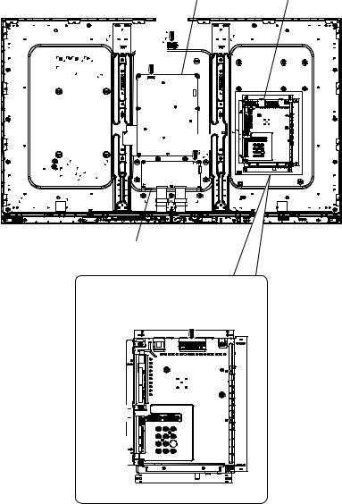
4. Removing of 60” LCD Panel Module Unit, LCD CONTROL Unit, MAIN Unit, POWER Unit.
1.Remove the 8 lock screws  .
.
2.Detach the 14 Fixing Metal Angles  .
.
3.Remove the 8 Hooks and detach the 60” LCD Panel Module Unit  .
.
4.Remove the 2 Connecting Cords  , 2 Cores
  and 6 lock screws
  and detach the LCD CONTROL Unit
  .
.
5.Remove the 5 lock screws  and detach the MAIN PWB Shield
  .
.
6.Remove the 2 lock screws  and detach the MAIN Unit
  and remove the Hexagon screw
  (except LC-60LE636E(B)/S(B)) and Terminal Angle (Bottom)
  and Spring (Tuner)
  .
.
7.Remove the 6 lock screws  and detach the POWER Unit
  and remove 1lock Tray Shaft
  and detach AC Cord Barrier
  .
.
8.Remove the 8 lock screws  and detach the 2 Center Angles
  .
.
POWER Unit
14
13
20 AC Cord Barrier 15
Fixing Metal 2
Angle
Fixing Metal 2
Angle
1
16
|
MAIN PWB |
9 |
|
Shield |
|
|
11 |
8 |
MAIN Unit 12 |
|
|
Terminal Angle |
10 |
|
(Bottom) |
|
|
|
|
19 Spring |
Fixing Metal |
|
(Tuner) |
|
|
|
Angle 2 |
18 |
2 Fixing Metal |
|
|
Angle |
2 Fixing Metal
Angle
|
|
|
3 60" LCD Panel |
|
Hook |
|
Module Unit |
|
|
Hook |
|
1 |
|
|
6 |
16 |
Core |
5 |
7 LCD CONTROL Unit |
|
|
4 Connecting
Cord
Center
Angle
17 |
|
|
|
1 |
1 |
17 Center |
|
Angle |
|||
|
|
4 – 5

LC-60LE635E(B),RU(B)/636E(B),S(B)/638E(B)
5. Removing of R/C OPC Unit, ICON Unit.
1.Detach the R/C OPC Unit  .
.
2.Disconnect the RA wire.
3.Remove the 1 lock screw  and detach the ICON Unit
  .
.
4.Disconnect the CI wire.
Front Cabinet Ass'y
[RA] |
[CI] |
R/C OPC Unit 1 |
ICON Unit 3 |
2
4 – 6
 Loading...