


SCX-4521F

Disassembly and Reassembly
Samsung Electronics
Service Manual
5-1
5
5. Disassembly and Reassembly
5.1 General Precautions on Disassembly
When you disassemble and reassemble components, you must use extreme caution. The close proximity of cables
to moving parts makes proper routing a must.
If components are removed, any cables disturbed by the procedure must be restored as close as possible to their
original positions. Before removing any component from the machine, note the cable routing that will be affected.
Whenever servicing the machine, you
must perform as follows:
1. Check to verify that documents are not stored in
memory .
2. Be sure to remove the toner cartridge before you
disassemble parts.
3. Unplug the power cord.
4. Use a flat and clean surface.
5. Replace only with authorized components.
6. Do not force plastic-material components.
7. Make sure all components are in their proper posi-
tion.
Releasing Plastic Latches
Many of the parts are held in place with plastic latches.
The latches break easily; release them carefully.
To remove such parts, press the hook end of the latch
away from the part to which it is latched.
Samsung Electronics
Service Manual
Disassembly and Reassembly
5-2
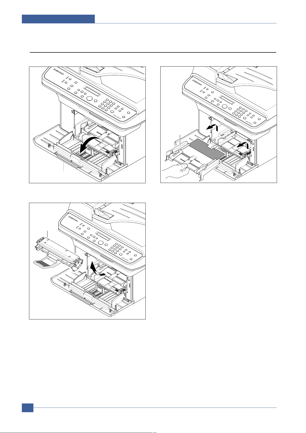
5.2 MP Tray
1. Open the Front Cover.
2. Release the Toner Cartridge.
3. Hold the MP Tray and pull it to the arrow direction.
Front Cover
Toner Cartridge
MP Tray
Disassembly and Reassembly
Samsung Electronics
Service Manual
5-3
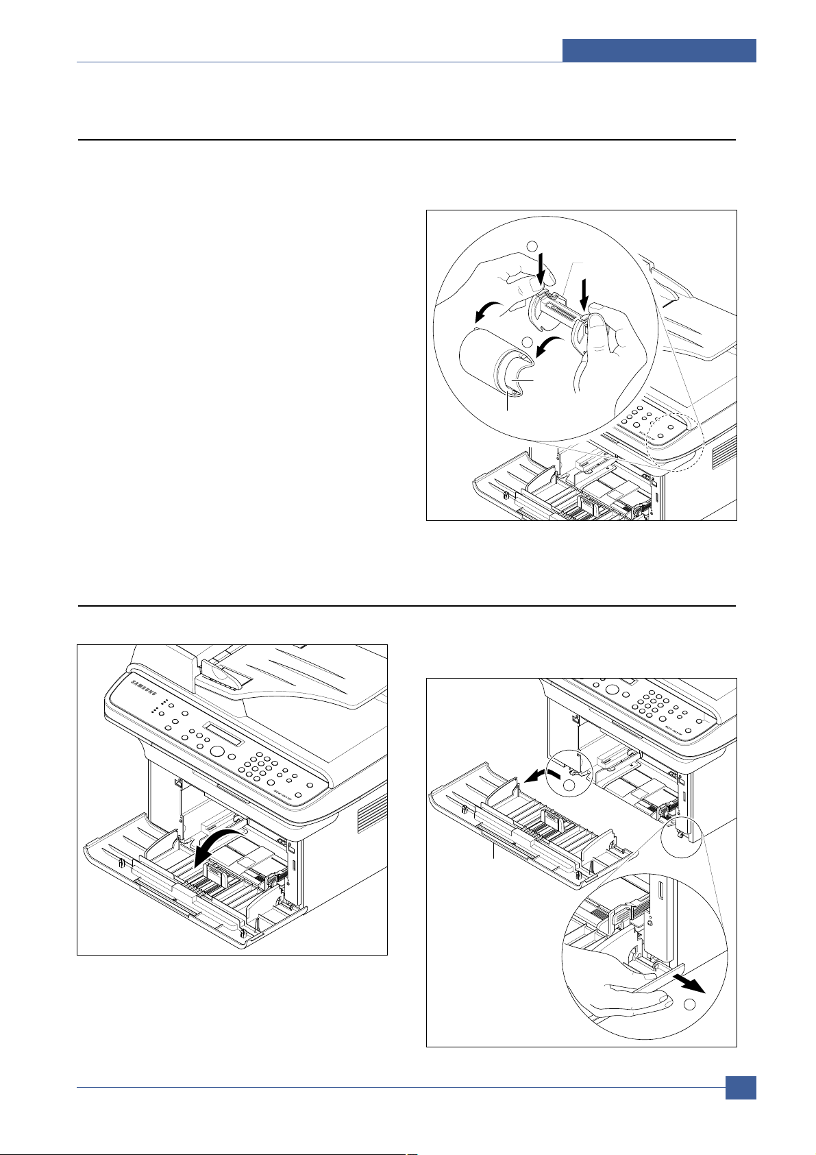
5.3 Pick Up Roller
1. Before you remove the Pick Up Roller, you should
remove:
- MP Tray (Refer to the 5.2)
2. To exchange Pick Up Sponge, pull part Pick Up
Housing U while pressing the hook on the both
side the Pick Up Housing B.
Housing B
2
1
Housing U
Sponge
5.4 Front Cover
1. Open the Front Cover. 2. To remove the Front Cover, first pull the part below
the right side of the Front Cover with a light pressure
to the direction of arrow(left).
Front Cover
2
1
Samsung Electronics
Service Manual
Disassembly and Reassembly
5-4
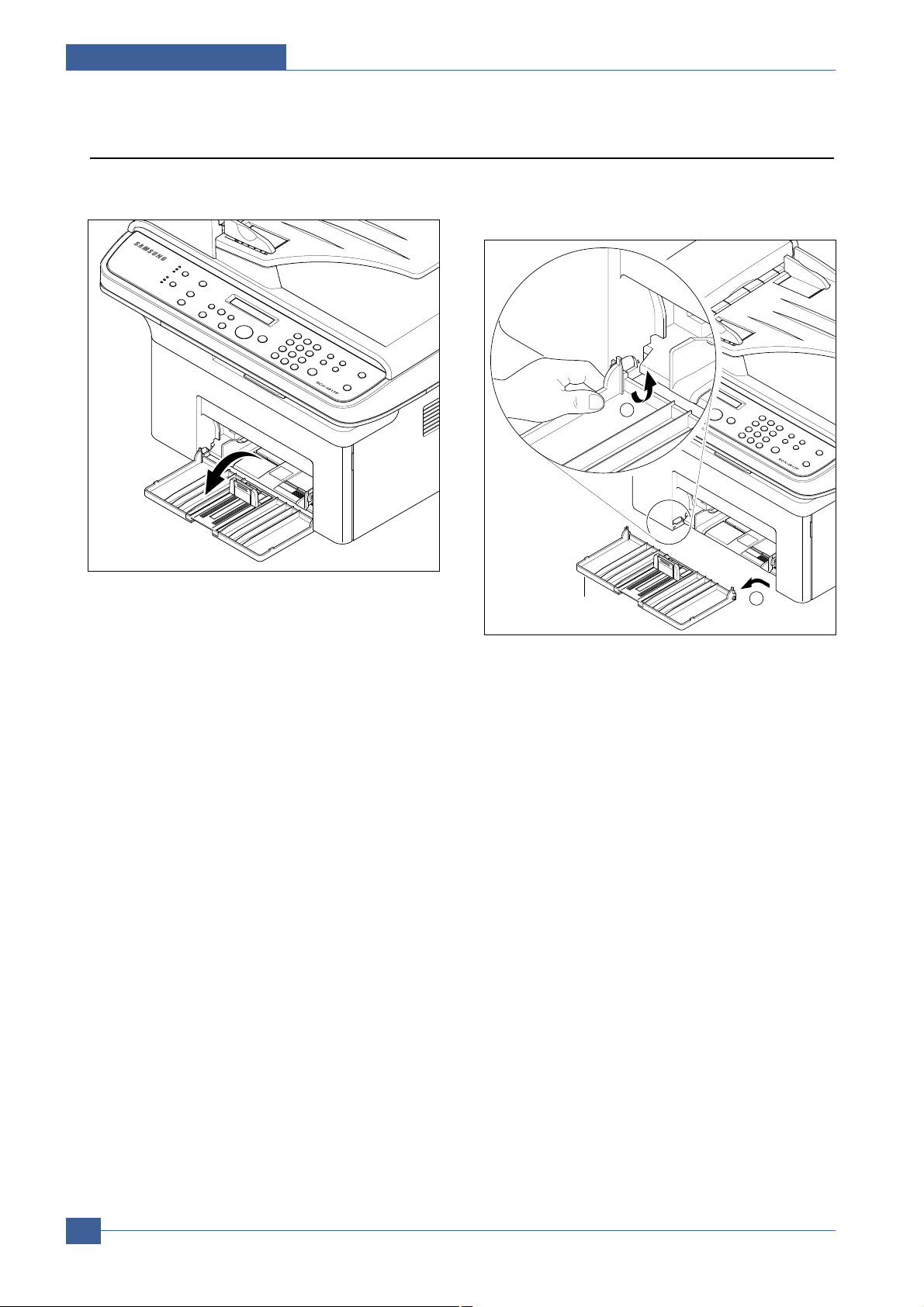
5.5 Cassette Tray
1. Open the Cassette Tray. 2. As shown below, to remove the Cassette Tray, lift
the nob to the direction of the arrow with a light
pressure while holding the Set(left).
Cassette Tray
2
1
Disassembly and Reassembly
Samsung Electronics
Service Manual
5-5
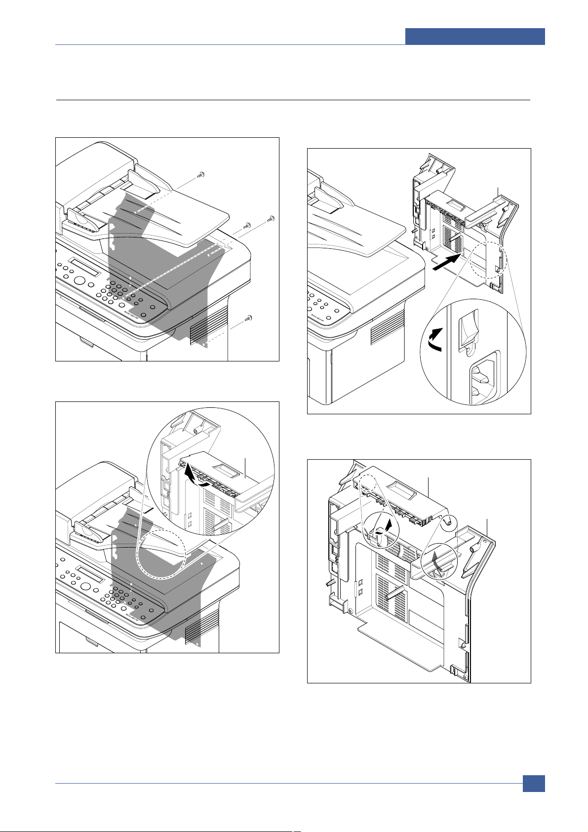
5.6 Rear Cover
1. Remove the four screws securing the Rear Cover
and remove it.
2. Open the Jam Cover.
3. To remove the Rear cover make sure the right
Power Switch doesn't get jammed to the Rear
Cover, as shown below.
4. If necessary, remove the Jam Cover in the direction
of arrow, as shown below.
Jam Cover
Rear Cover
Jam Cover
Rear Cover
Samsung Electronics
Service Manual
Disassembly and Reassembly
5-6
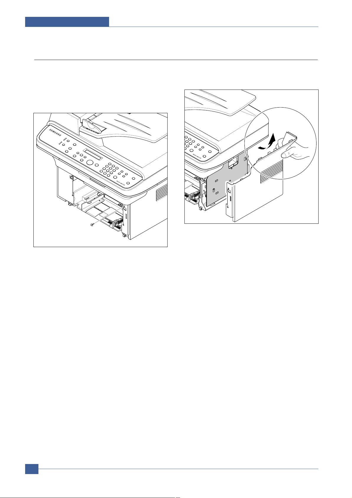
5.7 Right Cover
1. Before you remove the Right Cover, you should
remove:
- Front Cover (Refer to the 5.4)
- Rear Cover (Refer to the 5.6)
2. Remove the one screws securing the Right Cover.
3. Apply light pressure to the back of the Right Cover
and pull it to the right side in the direction of arrow,
as shown below.
Right Cover
Disassembly and Reassembly
Samsung Electronics
Service Manual
5-7
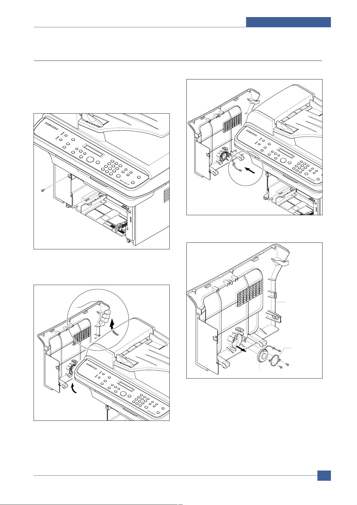
5.8 Left Cover
1. Before you remove the Left Cover, you should
remove:
- Front Cover (Refer to the 5.4)
- Rear Cover (Refer to the 5.6)
2. Remove the one screws securing the Left Cover.
3. Apply light pressure to the back of the Left Cover
and pull it to the leftt side in the direction of arrow,
as shown below.
4. Unplug the Speaker Connector from the Main PBA.
5. If necessary, remove the two screws securing the
Speaker and remove it.
Left Cover
Speaker
Left Cover
Speaker
Fixing Bracket
 Loading...