


NETWORK CAMERA
User Manual
PNM-9000VQ
SLA-2M2400Q/2M2800Q/2M3600Q/ 2M6000Q/5M3700Q/5M4600Q/5M7000Q


overview
Important Safety Instructions
1.Read these instructions.
2.Keep these instructions.
3.Heed all warnings.
4.Follow all instructions.
5.Do not use this apparatus near water.
6.Clean the contaminated area on the product surface with a soft, dry cloth or a damp cloth.
(Do not use a detergent or cosmetic products that contain alcohol, solvents or surfactants or oil constituents as they may deform or cause damage to the product.)
7.Do not block any ventilation openings, Install in accordance with the manufacturer’s instructions.
8.Do not install near any heat sources such as radiators, heat registers, stoves, or other apparatus (including amplifiers) that produce heat.
9.Do not defeat the safety purpose of the polarized or grounding-type plug. A polarized plug has two blades with one wider than the other. A grounding type plug has two blades and a third grounding prong. The wide blade or the third prong are provided for your safety. If the provided plug does not fit into your outlet, consult an electrician for replacement of the obsolete outlet.
10.Protect the power cord from being walked on or pinched particularly at plugs, convenience receptacles, and the point where they exit from the apparatus.
11.Only use attachments/ accessories specified by the manufacturer.
12.Use only with the cart, stand, tripod, bracket, or table specified by the manufacturer,
or sold with the apparatus. When a cart is used, use caution when moving the cart/  apparatus combination to avoid injury from tip-over.
13. Unplug this apparatus during lighting storms or when unused for long periods of time.
14. Refer all servicing to qualified service personnel. Servicing is required when the apparatus has been damaged in any way, such as power-supply cord or plug is damaged, liquid has
been spilled or objects have fallen into the apparatus, the apparatus has been exposed to rain or moisture, does not operate normally, or has been dropped.
15.This product is intended to be supplied by a Listed Power Supply Unit marked “Class 2” or “LPS” and rated from / PoE , 0.6A. (PNM-9000VQ)
16.This Lens module has to be connected with equipment, which supplied by a power supply unit marked “Class 2” or “LPS”. (SLA-2M2400Q/2M2800Q/2M3600Q/2M6000Q/5M3700Q/5M4600Q/5M7000Q)
17.If you use excessive force when installing the product, the camera may be damaged and malfunction. If you forcibly install the product using non-compliant tools, the product may be damaged.
18.Do not install the product in a place where chemical substances or oil mist exists or may be generated. As edible oils such as soybean oil may damage or warp the product, do not install the product in the kitchen or near the kitchen table.
This may cause damage to the product.
19.When installing the product, be careful not to allow the surface of the product to be stained with chemical substance.
Some chemical solvents such as cleaner or adhesives may cause serious damage to the product’s surface.
20.If you install/disassemble the product in a manner that has not been recommended, the production functions/ performance may not be guaranteed.
Install the product by referring to “Installation & connection” in the user manual.
21.Installing or using the product in water can cause serious damage to the product.
WARNING
TO REDUCE THE RISK OF FIRE OR ELECTRIC SHOCK, DO NOT EXPOSE THIS PRODUCT TO RAIN OR MOISTURE. DO NOT INSERT ANY METALLIC OBJECT THROUGH THE VENTILATION GRILLS OR OTHER OPENNINGS ON THE EQUIPMENT.
Apparatus shall not be exposed to dripping or splashing and that no objects filled with liquids, such as vases, shall be placed on the apparatus.
To prevent injury, this apparatus must be securely attached to the Wall/ceiling in accordance with the installation instructions.
CAUTION
CAUTION
RISK OF ELECTRIC SHOCK.
DO NOT OPEN
CAUTION : TO REDUCE THE RISK OF ELECTRIC SHOCK.
DO NOT REMOVE COVER (OR BACK).
NO USER SERVICEABLE PARTS INSIDE.
REFER SERVICING TO QUALIFIED SERVICE PERSONNEL.
EXPLANATION OF GRAPHICAL SYMBOLS
The lightning flash with arrowhead symbol, within an equilateral triangle, is intended to alert the user to the presence of “dangerous voltage” within the product’s enclosure that may be of sufficient magnitude to constitute a risk of electric shock to persons.
The exclamation point within an equilateral triangle is intended to alert the user to the presence of important operating and maintenance (servicing) instructions in the literature accompanying the product.
overview ●●
English _3

overview
Class  construction
An apparatus with CLASS construction shall be connected to a MAINS socket outlet with a protective earthing connection.
Battery
Batteries(battery pack or batteries installed) shall not be exposed to excessive heat such as sunshine, fire or the like.
Disconnection Device
Disconnect the main plug from the apparatus, if it’s defected. And please call a repair man in your location.
When used outside of the U.S., it may be used HAR code with fittings of an approved agency is employed.
CAUTION
RISK OF EXPLOSION IF BATTERY IS REPLACED BY AN INCORRECT TYPE. DISPOSE OF USED BATTERIES ACCORDING TO THE INSTRUCTIONS.
ATTENTION
IL Y A RISQUE D’EXPLOSION SI LA BATTERIE EST REMPLACÉE PAR UNE BATTERIE DE TYPE INCORRECT.
METTRE AU REBUT LES BATTERIES USAGÉES CONFORMÉMENT AUX INSTRUCTIONS.
These servicing instructions are for use by qualified service personnel only.
To reduce the risk of electric shock do not perform any servicing other than that contained in the operating instructions unless you are qualified to do so.
The CVBS out terminal of the product is provided for easier installation, and is not recommended for monitoring purposes.
Please use the input power with just one camera and other devices must not be connected.
The ITE is to be connected only to PoE networks without routing to the outside plant. The wired LAN hub providing power over the Ethernet (PoE) in accordance with IEEE 802-3af shall be a UL Listed device with the output evaluated as a Limited Power Source as defined in UL60950-1.
Unit is intended for installation in a Network Environment 0 as defined in IEC TR 62102. As such, associated Ethernet wiring shall be limited to inside the building.
Please read the following recommended safety precautions carefully.
yyDo not place this apparatus on an uneven surface.
yyDo not install on a surface where it is exposed to direct sunlight, near heating equipment or heavy cold area.
yyDo not place this apparatus near conductive material. yyDo not attempt to service this apparatus yourself. yyDo not place a glass of water on the product.
yyDo not install near any magnetic sources. yyDo not block any ventilation openings. yyDo not place heavy items on the product.
yyPlease wear protective gloves when installing/removing the camera. The high temperature of the product surface may cause a burn.
User’s Manual is a guidance book for how to use the products. The meaning of the symbols are shown below.
yyReference : In case of providing information for helping of product’s usages
yyNotice : If there’s any possibility to occur any damages for the goods and human caused by not following the instruction
Please read this manual for the safety before using of goods and keep it in the safe place.
4_ overview

CONTENTS
overview
3
3 Important Safety Instructions
6 Product Features
6 Recommended PC Specifications
6Recommended Micro SD/SDHC/SDXC Memory Card Specifications
7What’s Included (PNM-9000VQ)
8What’s Included (Lens module -optional)
8At a Glance (PNM-9000VQ)
9At a Glance (Lens module)
installation & connection |
10 |
Installation |
10 |
17 |
Connecting with other Device |
network connection and setup
18
18 Connecting the Camera Directly to Local Area Networking
18 Connecting the Camera Directly to a DHCP Based DSL/Cable Modem
19 Buttons used in IP Installer
19 Static IP Setup
21 Dynamic IP Setup
21 Port Range Forward (Port Mapping) Setup
22 Connecting to the Camera from a Shared Local PC
22Connecting to the Camera from a Remote PC via the Internet
web viewer |
24 |
Password setting |
23 |
23 |
Connecting to the Camera |
24 |
Login |
|
24 |
Camera Web Viewer Setup |
|
appendix |
27 |
Specification (Lens module) |
25 |
25 |
Specification (PNM-9000VQ) |
28 |
Product Overview |
|
29 |
Troubleshooting |
|
30 |
Open Source Announcement |
overview ●●
English _5

overview
Product Features
•• Lens options according to focal length
You can select the lens you want and attach it to the camera.
•• 4-way Camera
Each of the four camera lenses monitors a different direction.
•• Dustproof/Waterproof
The dust-resistant/water-resistant design protects the product from rain and dust when installed outdoors. (IP66)
•• Multi-Streaming
This network camera can display videos in different resolutions and qualities simultaneously using different CODECs.
•• Web Browser-based Monitoring
Using the Internet web browser to display the image in a local network environment.
•• Alarm
When an event occurs, related videos are sent to the user’s registered e-mail and FTP server or stored on the Micro SD memory card.
•• Tampering Detection
Detects tempering attempts on video monitoring.
•• Defocus detection function
Detects the defocus phenomenon of the camera lens.
•• Motion Detection
Detects motion from the camera’s video input.
•• Fog detection
Detects fog that is heavier than the detection level.
•• Face Detection
Detects faces in the specified area from the camera’s video input.
•• IVA (Intelligent Video Analysis) function
Detects a motion or situation that meets the configured event rules.
•• ONVIF Compliance
This product supports ONVIF Profile S.
For more information, refer to www.onvif.org.
Recommended PC Specifications
•• CPU : Intel(R) Core(TM) i7 3.4 GHz or higher
•• Supported OS : MS Windows, Mac OS X
•• Plug-in free web viewer
Supported web browsers : Google Chrome, MS Edge, Mozilla Firefox (Windows 64bit only), Apple Safari (Mac OS X only)
Please see the appendix for detailed information on verified OS and browsers. Some functions may be restricted even in supported browsers.
Recommended Micro SD/SDHC/SDXC Memory Card
Specifications
•• Recommended capacity : 16GB to 256GB (MLC type)
•• The following types of memory cards from the following manufacturers are recommended for this camera. -- Manufacturer : SanDisk, Transcend
-- Product family : High endurance
•• It is recommended to use a memory card of 16GB or more that conforms to the UHS-3 class (MLC type) specification.
6_ overview

What’s Included (PNM-9000VQ) |
|
|
|
Please check if your camera and accessories are all included in the product package. |
|||
(As for each sales country, accessories are not the same.) |
|
|
|
Appearance |
Item Name |
Quantity |
Description |
|
Camera |
1 |
|
|
Instruction book, |
1 |
|
|
Installer S/W CD |
|
|
|
|
|
|
|
Quick Guide |
1 |
|
|
(Optional) |
|
|
|
|
|
|
|
Warranty card |
1 |
|
|
(Optional) |
|
|
|
|
|
|
|
Cable for the testing monitor |
1 |
Used to test the camera connection to a portable |
|
display device |
||
|
|
|
|
|
Template |
1 |
Product installation guide |
|
L Wrench |
1 |
Used to remove and replace the dome cover |
|
Tapping Screw |
4 |
Used for installation on the wall or ceiling |
|
Plastic Anchor |
4 |
For fixing a screw, Inserted in a hole |
|
(reinforced anchoring force) |
||
|
|
|
|
Appearance |
Item Name |
Quantity |
Description |
|
Machine Screws |
4 |
Used for assembling the dome case when installing |
|
the product on the pipe, wall mount, etc. or blocking a |
||
|
|
|
hole. |
|
Cap Installer |
1 |
Used to connect the RJ45 cable. |
|
Card-type moisture absorbent |
1 |
Attached when installed. |
|
Drill bit |
1 |
Used for dome cover disassembly, |
|
assembly and camera installation. |
||
|
|
|
|
|
Cable bush |
1 |
Used to connect the LAN cable with a diameter of |
|
Ø7~8.5. |
||
|
|
|
|
|
|
|
Used to block the high-frequency component(s) |
|
Ferrite Core |
1 |
contained in the power supply and the signal end from |
|
being radiated to the outside |
||
|
|
|
`` It is recommended to wind it 2 times around the |
|
|
|
power cable and the LAN cable before use. |
overview ●●
English _7

overview
What’s Included (Lens module -optional)
Appearance |
Item Name |
Quantity |
Description |
Model Name |
|
|
1 |
|
SLA-2M2400Q |
|
|
1 |
|
SLA-2M2800Q |
|
|
1 |
|
SLA-2M3600Q |
|
Lens module |
1 |
Mounted to PNM-9000VQ |
SLA-2M6000Q |
|
|
1 |
|
SLA-5M3700Q |
|
|
1 |
|
SLA-5M4600Q |
|
|
1 |
|
SLA-5M7000Q |
At a Glance (PNM-9000VQ)
Appearance
a
b
Item |
Description |
a Dome cover |
Case cover used to protect the lens and the main unit. |
|
|
b Camera Case |
Housing part that covers the camera body. |
|
|
8_ overview

Components |
|
|
|
|
|
|
|
|
|
|
|
|
|
At a Glance (Lens module) |
|
|
|
|
|
|
|
|
|
|
|
|
|
|
h |
Appearance |
|
|
|
|
|
|
|
|
|
|
4 |
|
|
|
|
a |
b |
|
|
|
|
|
|
|
|
|
|
|
|
|
|
||
|
|
|
|
3 |
|
|
|
|
|
|
g |
|
|
||
|
|
|
|
|
|
|
|
|
2 |
|
|
|
f |
|
|
a |
|
|
|
|
|
|
|
|
|
|
4 |
RESET |
|
|
|
|
|
|
|
|
|
|
|
|
|
4 |
|
|
|
||
|
|
|
|
when |
|
|
|
|
|
|
|
CH |
|
|
|
|
|
|
|
|
. |
|
|
|
3 |
|
3 |
|
|
|
|
|
|
|
|
|
change |
module |
ON / |
|
|
|
|
|
|
|
|
b |
|
|
0 |
o |
2 |
0 |
VIDEO |
CH |
|
|
|
|
Item |
Description |
|
10 |
: CH |
1 |
2 |
|
|
|
|||||||||
|
2 |
Please turn |
lens |
|
|
OFF |
2 |
|
|
|
|
|
|||
|
01 |
: CH 3 |
|
|
|
|
|
CH |
|
|
|
|
|
||
|
11 |
: CH 4 |
1 |
CH |
|
|
1 |
|
|
|
|
|
|
||
|
|
|
|
ON |
1 |
|
|
LENS 1 |
|
|
|
|
|
|
|
c |
|
|
|
|
|
|
|
|
|
|
|
|
e |
a Lens module |
This is a lens module that records video. |
d |
|
|
|
|
|
|
|
|
|
|
|
|
|
||
|
|
|
|
|
|
|
|
|
|
|
|
|
b Camera connector |
|
|
Item |
|
|
|
|
|
|
|
|
|
|
|
Description |
|
This is a terminal to connect with the camera. |
|
|
|
|
|
|
|
|
|
|
|
|
|
|
|
||
a Power On/Off switch |
Switch used to turn the product On/off. |
|
J Use |
it only to replace your lens module. |
|
b DIP switch for changing the |
Change the DIP switches to specify the channel you want to use to view the installation |
|
channel |
video. |
|
c Test Monitor Out |
Output port for test monitoring the video output. Use the test monitor cable to connect to a |
|
mobile display and check the test video. |
||
d Lens module indication light |
If the lens module is attached correctly, the green LED will illuminate and then turn off after |
|
(normal: green, abnormal: red) |
approximately 40 seconds. (to prevent undesirable reflections) |
|
Micro SD Memory Card |
Compartment for the Micro SD memory card. |
|
e Compartment |
||
|
The button restores all camera settings to the factory default. |
|
|
Press and hold for about 5 seconds to reboot the system. |
|
f Reset Button |
J If you reset the camera, the network settings will be adjusted so that DHCP can be |
|
enabled. If there is no DHCP server in the network, you must run the IP Installer |
||
|
program to change the basic network settings such as IP address, Subnet mask, |
|
|
Gateway, etc., before you can connect to the network. |
|
g portionLens module mounting |
This is the terminal to mount the lens module. |
|
h PoE+ Connection Terminal |
The terminal connects power and network through the PoE+ cable. |
|
overview ●●
English _9
installation & connection
Installation
JJ`` This camera is waterproof and in compliance with the IP66 spec, but the jack connected to the external cable is not. You are recommended to install this product below the edge of eaves to prevent the cable from being externally exposed.
Precautions before installation
Ensure you read out the following instructions before installing the camera:
•• Select an installation site that can hold at least 5 times the camera’s weight.
•• Stuck-in or peeled-off cables can cause damage to the product or a fire.
•• For safety purposes, keep anyone else away from the installation site. And put aside personal belongings from the site, just in case.
•• If the product is installed with excessive force, it may cause damage to the camera due to malfunction. Forcing assembly using non-compliant tools may damage the product.
•• Do not remove the lens module while the power is on.
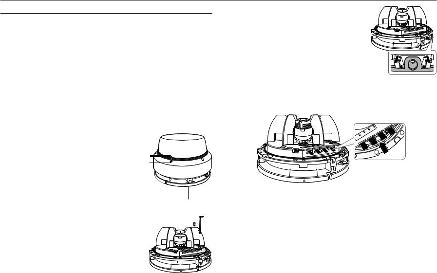
Disassembling
1. Remove the dome cover by loosening the fastening |
Dome cover |
|
bolt of the dome cover. This can be done by turning it |
|
|
counterclockwise using the Allen key or drill bit provided. |
|
|
Fastening bolt |
Camera Body


Mount plate
2. Loosen the fastening screw on the camera body.
3. Remove the camera body and mounting plate by pulling the plate spring, as shown in the figure.
Inserting a Micro SD Memory Card
1.Remove the dome cover of the camera.
2.Insert a Micro SD card in the arrow direction shown in the figure.
|
3 |
4 |
3 |
|
|
||
|
|
|
|
2 |
2 |
|
|
1 |
CH |
|
|
LENS 1 |
|
|
|
CH |
|
|
|
VIDEO
JJ`` Disconnect the power cable from the camera before inserting the Micro SD memory card.
`` Do not forcefully insert it in the reverse direction. It might damage your Micro SD memory card and your product. `` When it rains or the humidity is high, insertion or ejection of a Micro SD card is not recommended.
`` Disassembly of the product cover should be finished within 5 minutes, or there will be the risk of internal dew condensation.
10_ installation & connection
Removing a Micro SD Memory Card
Gently press down on the exposed end of the memory card as shown in the diagram to eject the memory card from the slot.
|
3 |
4 |
3 |
|
|
||
|
|
|
|
2 |
2 |
|
|
1 |
CH |
|
|
LENS 1 |
|
|
|
CH |
|
|
|
VIDEO
Mounting lens module
1.Align and fasten the connector of the lens module with the connector of the camera body.
JJ`` Install the lens module while power is not connected (PoE+).
`` Check if the power switch is “OFF” before installing the lens module.
`` You are recommended to avoid touching the lens separately, as it is shipped from the factory with the focus adjusted during the manufacturing inspection.
connectionin&●sta●ationll
JJ`` You should save an SD card for each channel.
`` Please note that if you firmly push and release the Micro SD memory card when it is ejected, it may pop out.
`` Before removing the Micro SD memory card, in <Storage>, set the device to <Off> and press the [Apply] button and turn the camera off.
`` If you turn off the camera or remove the Micro SD memory card that contains data from the product, the data may be lost or damaged.
2. Complete the lens mounting process.
3. Connect power to the product (PoE+).
JJ`` If you want to replace the lens module while connecting power to the product (PoE+), turn the power switch “OFF”, replace the lens module, and then turn the power switch “ON”.
`` Be careful not to use any tool with a sharp point when handling the switch since it might be damaged.
`` Be careful not to forcefully handle the switch since it might be damaged.
English _11

installation & connection
How to install using the perpendicular falling method
You can move the lens for only one channel to see the video after installing it in the direct-lit manner. In this case, the lens direction of the moved channel can be tilted up to 90 degrees.
1. Tilt the lens module part forward-facing and then pull it.
2. Align the groove with the center of the rotating part.
3. |
Lift the part with diagonal lines to release the frame |
Frame Pan |
|
|
|
|
|
|
|
4. |
pan. |
|
|
|
|
||||
Move the three channel lenses along the bottom rail. |
|
|
|
|
|
|
|
|
|
|
|
|
|
|
|
|
|
||
|
|
|
|
|
|
|
|
|
|
How to install using the tilting method
You can move the lenses of CH1 - CH4 along the bottom rail to view videos by installing them using the tilting method.
In this case, the orientation of the lens cannot be tilted by 90 degrees.
1. Mount the frame pan.
2. Remove the direct-lit lens from the rotation center. 3. Move the four channel lenses along the bottom rail.
12_ installation & connection
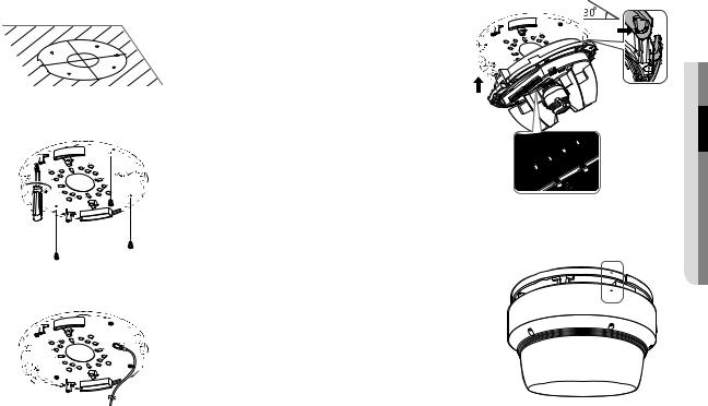
Installation on a ceiling or wall
1.Use the provided template to drill holes for installation (diameter 6 mm and minimum depth 45mm) and insert the supplied plastic anchors to the end.
2. Align the holes of the mount plate for installation with the holes inserted with plastic anchors, and fasten the tapping screws.
FRONT
3. Connect the safety cable.
4.Mount the camera body to the mount plate.
`` Mount it to fit the hinges as shown in the image.
5. Connect the terminal inside camera with the required cable.
JJ`` If the lens module is not attached correctly, the lens module status light will illuminate red, as shown in the figure. If this occurs, turn off the power switch and reattach the lens module. If attached normally, it will illuminate green and then turn off after approximately 40 seconds.
6.Push in the pin spring.
7.Adjust the lens to the desired direction by referring to “Adjusting the monitoring direction for the camera”. (Page 17)
`` If you tilt the lens, you may need to adjust the lens as this may block the screen.
8.Assemble the dome cover.
`` Align the arrows when assembling the dome cover.
`` To ensure there are no issues with waterproofing, tighten the fastening bolts tightly using the Allen key or drill bit.
1
LENS 1 CH
2
4 3
2 CH
3
connectionin&●sta●ationll
English _13
 Loading...