


10. Designation of Main Components
10-1 Normal / Reverse Revolution of Motor and R. P. M. Control
8 |
Rotor |
9 |
+ |
|
|
|
CW |
5 |
Stator coil |
10 |
- |
|
|
|
|
8 |
Rotor |
9 |
+ |
|
|
||
|
|
|
|
|
|
5 |
CCW |
|
|
- |
|
|
|
|
|
|
Stator coil |
10 |
|
5
1 |
2 |
3 |
4 |
5 |
6 |
7 |
8 |
9 |
10 |
|
|
|
|
|
|
|
|
|
|
|
|
|
|
|
|
|
|
|
|
|
|
|
|
|
|
|
|
|
|
|
|
|
|
|
|
|
SPEED-HIGH |
|
|
|
SPEED-MIDDLE |
|
|
|
|
|
|
|
|
|
|||
|
|
CHOAT |
|
|
|
ORTECT C) O (150 PR |
|
|
|
|
|
||||||
|
|
|
|
|
|
|
|
|
|||||||||
|
|
|
|
|
|
|
|
|
|
|
|
|
ORTO R |
|
|
|
|
|
|
|
|
|
|
|
|
|
|
|
|
||||||
|
|
|
|
|
|
|
ORTAST |
|
|
|
|
|
|||||
|
|
|
|
|
|
|
|
|
|
|
|
|
|
|
|
||
|
|
|
|
|
|
|
|
|
|
|
|
|
|
|
|||
|
|
|
|
|
|
|
|
|
|
|
|
|
|
|
|
|
|


 STATOR
WASHING MOT OR
H |
|
<Figure1> |
|
|
|
<Figure2> |
|
|
|
|
|||
|
|
|
|
|
|
|
|
|
|
|
||
(? ? ? ? |
|
S TAT O R(5.1) |
ST AT O R(5.1) |
R OT O R(8.9) |
|
TA C HO (3 .4) |
PR OT EC T OR (6.7) |
"H "(m m ) |
C ode-N o. |
R em ark |
||
|
|
|
|
|
|
|
|
|
|
|
|
|
R es is ta n c e |
2.07 |
? |
0.90? |
2.35 ? |
|
34.?? |
|
0 |
45 |
DC 31-00002E |
|
|
v a lu e |
|
|
|
|
||||||||
|
|
|
|
|
|
|
|
|
|
|
|
|
Rated |
|
|
|
|
|
|
220~240V/50Hz |
|
|
|
|
|
value |
|
|
|
|
|
|
|
|
|
|
||
|
|
|
|
|
|
|
|
|
|
|
|
|
10-2 Door safety Device (F1213J/F1013J/F813J)
When Door is closed, door stay closed. if "set" is operated, |
power supplied to |
, |
|
|
wires have bymetal keep |
|||||||||||||||||||||||||||||||||||||||||||||||||||||||
the door closed, and electronical power flows between |
and |
|
|
|
|
make it operate. |
|
|
|
|
||||||||||||||||||||||||||||||||||||||||||||||||||
|
|
|
|
|
|
|
|
|
|
|
|
|
|
|
|
|
|
|
|
|
|
|
|
|
|
|
|
|
|
|
|
|
|
|
|
|
|
|
|
|
|
|
|
|
|
|
|
|
|
|
|
|
|
|
|
|
|
|
|
|
|
|
|
|
|
|
|
|
|
|
|
|
|
|
|
|
|
|
|
|
|
|
|
|
|
|
|
|
|
|
|
|
|
|
|
|
|
|
|
|
|
|
|
|
|
|
|
|
|
|
|
|
|
|
|
|
|
|
|
|
|
|
|
|
|
|
|
|
|
|
|
|
|
|
|
|
|
|
|
|
|
|
|
|
|
|
|
|
|
|
|
|
|
|
|
|
|
|
|
|
|
|
|
|
|
|
|
|
|
|
|
|
|
|
|
|
|
|
|
|
|
|
|
|
|
|
|
|
|
|
|
|
|
|
|
|
|
|
|
|
|
|
|
|
|
|
|
|
|
|
|
|
|
|
|
|
|
|
|
|
|
|
|
|
|
|
|
|
|
|
|
|
|
|
|
|
|
|
|
|
|
|
|
|
|
|
|
|
|
|
|
|
|
|
|
|
|
|
|
|
|
|
|
|
|
|
|
|
|
|
|
|
|
|
|
|
|
|
|
|
|
|
|
|
|
|
|
|
|
|
|
|
|
|
|
|
|
|
|
|
|
|
|
|
|
|
|
|
|
|
|
|
|
|
|
|
|
|
|
|
|
|
|
|
|
|
|
|
|
|
|
|
|
|
|
|
|
|
|
|
|
|
|
|
|
|
|
|
|
|
|
|
|
|
|
|
|
|
|
|
|
|
|
|
|
|
|
|
|
|
|
|
|
|
|
|
|
|
|
|
|
|
|
|
|
|
|
|
|
|
|
|
|
|
|
|
|
|
|
|
|
|
|
|
|
|
|
|
|
|
|
|
|
|
|
|
|
|
|
|
|
|
|
|
|
|
10-2 Door safety Device (F1215J/F1015J/F815J) |
1 |
4 |
3 |
2 |
23
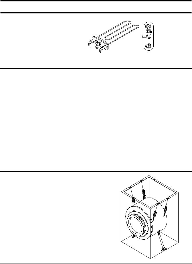
10-3 Heater
1) Capacity : AC 230V/1900W |
|
|
2) |
Location : Bottom of TUB |
|
3) |
Function : Raise the water temperature |
Thermistor |
|
supplied at the wash process. |
|
4) |
Resistance value : 23~29 |
|
5) Thermal Fuse : 128°C |
|
|
10-4 Detergent tub and water supply value
A Detergent tub is composed of housing and 3 drawers . supplied water flows into the 3 drawer-detergent tub by
way of classifier at each washing process. |
|
|
|
|
|
||
three open drainage way whith detergent and supplied water by way of connector |
located under the |
housing flows |
|||||
into washing tub. |
|
|
|
|
|
|
|
the water supply valve is composed of a hot water valve(1 |
way) and |
a cold water |
valve(2way) and |
water flow per |
|||
min in the valve is below. |
|
|
|
|
|
|
|
|
|
|
|
|
|
|
|
|
Hot water valve(1 way) |
|
|
Cold water valve(2 way) |
|
||
|
(OPTION) |
|
|
V1 |
|
V2 |
|
water flow(L/min) |
10L |
|
|
10L |
|
|
5L |
resistance value |
4.3 |
|
|
4.2 |
|
4.2 |
|
power consumption |
|
|
AC 220v ~ 240V 50/60 |
|
|||
usable water pressure |
|
|
0.5 |
~ 8 / |
|
|
|
10-5 Shock absorber and buffer spring
This wash machine is equipped with 2 Shock absorbers with same capacity and with 4 buffer springs. 2 Shock absorber are placed under the tub and outside case , 4 buffer springs are placed on the right and left of the upper side of outside case.
Shock absorber function: during wash, dehydration absorb the shock. buffer spring: buffering the vibration
device |
capacity of Shock absorber |
Shock absorber |
8±2kg |
24

10-6 ASSY-TUB BACK
INNER-BEARING
OUT-BEARING |
|
|
B |
A |
C |
|
OIL-SEAL |
|
|
|
|
|
|
|
(unit : mm) |
|
TYPE |
INNER-BEARING(A) |
OUT-BEARING(B) |
OIL-SEAL(C) |
Assy-Housing |
Assy-Tub Back |
REMARK |
|
Bearing(D) |
|
||||||
|
|
|
|
|
|
|
|
I |
ø 20 |
ø 17 |
ø 24.3 |
DC97-00125A |
DC97-00214K |
|
|
|
|
|
|
|
|
|
|
10-7 ASSYDRUM
 A
A

 B
B
 C
C
|
|
|
|
|
(unit : mm) |
TYPE |
(A) |
(B) |
(C) |
CODE-NO. |
REMARK |
|
|
|
|
|
|
I |
ø 20 |
ø 17 |
ø 25 |
DC97-01463C |
Lifter type |
|
|
|
|
|
|
10-8 ASSY-PUMP DRAIN
1) Capacity : AC 230V 34W
2) Location : Front bottom(R)
3) Resistance : 160Ω~ 190Ω
25
 Loading...