


EKO 7
Table of contents
 Loading...
Diagnostic Ultrasound System
Operation Manual
VERSION 1.01.01
English
M353-E10101-00


PROPRIETRAY INFORMATION AND SOFTWARE LICENSE
The Customer shall keep confidential all proprietary information furnished or disclosed to the
Customer by SAMSUNG MEDISON, unless such information has become part of the public domain
through no fault of the Customer. The Customer shall not use such proprietary information, without
the prior written consent of SAMSUNG MEDISON, for any purpose other than the maintenance,
repair or operation of the goods.
SAMSUNG MEDISON’s systems contain SAMSUNG MEDISON’s proprietary software in machine-
readable form. SAMSUNG MEDISON retains all its rights, title and interest in the software except
that purchase of this product includes a license to use the machine-readable software contained in
it. The Customer shall not copy, trace, disassemble or modify the software. Transfer of this product
by the Customer shall constitute a transfer of this license that shall not be otherwise transferable.
Upon cancellation or termination of this contract or return of the goods for reasons other than repair
or modication, the Customer shall return to SAMSUNG MEDISON all such proprietary information.

Safety Requirements
■
Classications:
▶
Type of protection against electrical shock: Class I
▶
Degree of protection against electrical shock (Patient connection): Type BF equipment
▶
Degree of protection against harmful ingress of water: Ordinary equipment
▶
Degree of safety of application in the presence of a ammable anesthetic material with air or
with oxygen or nitrous oxide: Equipment not suitable for use in the presence of a ammable
anesthetic mixture with air or with oxygen or nitrous oxide.
▶
Mode of operation: Continuous operation
■
Electromechanical safety standards met:
▶
Medical Electrical Equipment, Part 1: General Requirements for Basic Safety and Essential
Performance [IEC 60601-1:2005]
▶
Medical Electrical Equipment, Part 1-2: General Requirements for Basic Safety and Essential
Performance - Collateral Standard: Electromagnetic Compatibility - Requirements and Tests [IEC
60601-1-2:2007]
▶
Medical Electrical Equipment, Part 1-6: General Requirements for Basic Safety and Essential
Performance- Collateral Standard: Usability [IEC 60601-1-6:2006]
▶
Medical Electrical Equipment, Part 2-37: Particular Requirements for the Basic Safety and
Essential Performance of Ultrasonic Medical Diagnostic and Monitoring Equipment [IEC60601-
2-37:2007]
▶
Medical Electrical Equipment, Part 1: General Requirements for Safety [IEC 60601-1:1988 with
A1:1991 and A2:1995]
▶
Medical Electrical Equipment, Part 1: General Requirements for Safety – 1 Collateral Standard:
safety Requirement for Medical Electrical Systems [IEC 60601-1-1:2000]
▶
Medical Electrical Equipment, Part 1: General Requirements for Safety - 2 Collateral Standard:
Electromagnetic Compatibility - Requirements and Test [IEC 60601-1-2:2001, A1:2004]
▶
Medical Electrical Equipment, Part 1: General Requirements for Safety - 4 Collateral Standard:
Programmable Electrical Medical Systems [IEC 60601-1-4: 1996, A1:1999]
▶
Medical Electrical Equipment, Part 2: Particular Requirements for Safety - 37 Ultrasonic Medical
Diagnostic and Monitoring Equipment [IEC60601-2-37: 2001 with A1:2004, A2:2005]
▶
Medical Devices – Application of Risk Management to Medical Devices [ISO 14971:2007]
▶
Medical Electrical Equipment, Part 1: General Requirements for Safety [UL60601-1:2003]
▶
Medical Electrical Equipment - Part 1: General Requirements for Safety [CAN/CSA 22.2
No.601.1-M90:1990, with R2003, with R2005]

▶
Biological Evaluation of Medical Devices [ISO10993 : 2009]
▶
Standard Means for the Reporting of the Acoustic Output of Medical Diagnostic Ultrasonic
Equipment [IEC61157:2007]
■
Declarations
This is CSA symbol for Canada and United States of America
This is manufacturer’s declaration of product compliance with
applicable EEC directive(s) and the European notied body.
This is manufacturer’s declaration of product compliance with
applicable EEC directive(s).

Read This First
How to Use Your Manual
This manual addresses the reader who is familiar with ultrasound techniques. Only medical doctors
or persons supervised by medical doctors should use this system. Sonography training and clinical
procedures are not included here. This manual is not intended to be used as training material for
the principles of ultrasound, anatomy, scanning techniques, or applications. You should be familiar
with all of these areas before attempting to use this manual or your ultrasound system.
This manual does not include diagnosis results or opinions. Also, check the measurement reference
for each application’s result measurement before the nal diagnosis.
It is useless to make constant or complex adjustments to the equipment controls. The system
has been preset at the factory to produce an optimum image in the majority of patients. User
adjustments are not usually required. If the user wishes to change image settings, the variables
may be set as desired. Optimal images are obtained with little difculty.
We are not responsible for errors that occur when the system is run on a user’s PC.
Non-SAMSUNG MEDISON product names may be trademarks of their respective owners.
Please keep this user guide close to the product as a reference when using the system.
For safe use of this product, you should read ‘Chapter1. Safety’ and ‘Chapter8. Maintenance’ in this
manual, prior to starting to use this system.
NOTE: Some features are not available in some countries. The features with options, and
specifications that this manual present can be changed without notice. Government approval is still
pending in some nations.
Conventions Used in This Manual
DANGER: Describes precautions necessary to prevent user hazards of great urgency. Ignoring a
DANGER warning will risk life-threatening injury.
WARNING: Used to indicate the presence of a hazard that can cause serious personal injury, or
substantial property damage.
CAUTION: Indicates the presence of a hazard that can cause equipment damage.
NOTE: A piece of information useful for installing, operating and maintaining a system. Not related
to any hazard.
If You Need Assistance
If you need any assistance with the equipment, like the service manual, please contact the
SAMSUNG MEDISON Customer Service Department or one of their worldwide customer service
representatives, immediately.

Revision History
DOCUMENT DATE REASON FOR CHANGE
M353-E10101-00 2011-05-18 Initial Release
System Upgrades and Manual Set Updates
SAMSUNG MEDISON Ultrasound is committed to innovation and continued improvement. Upgrades
may be announced that consist of hardware or software improvements. Updated manuals will
accompany those system upgrades.
Verify that Check if this version of the manual is correct for the system version. If not, please contact
the Customer Service Department.

Contents
9
Table of Contents
Chapter 1 Safety
TABLE OF CONTENTS .................................................................................................................... 9
INDICATION FOR USE ..................................................................................................................... 3
CONTRAINDICATIONS ............................................................................................................ 3
SAFETY SIGNS ................................................................................................................................ 4
SAFETY SYMBOLS .................................................................................................................. 4
SYMBOLS ................................................................................................................................. 5
LABELS .................................................................................................................................... 6
ELECTRICAL SAFETY ..................................................................................................................... 8
PREVENTION OF ELECTRIC SHOCK .................................................................................... 8
ECG-RELATED INFORMATION ............................................................................................. 10
ESD ......................................................................................................................................... 10
EMI ......................................................................................................................................... 11
EMC ........................................................................................................................................ 11
MECHANICAL SAFETY ................................................................................................................. 18
SAFETY NOTE ........................................................................................................................19
BIOLOGICAL SAFETY ................................................................................................................... 21
ALARA PRINCIPLE ................................................................................................................. 21
ENVIRONMENTAL PROTECTION ................................................................................................. 35
Chapter 2 Introduction
SPECIFICATIONS ............................................................................................................................. 3
PRODUCT CONFIGURATION ......................................................................................................... 5
MONITOR ................................................................................................................................. 7
CONTROL PANEL .................................................................................................................... 9
CONSOLE ............................................................................................................................... 15
PERIPHERAL DEVICES ........................................................................................................ 17
PROBE .................................................................................................................................... 19
ECG LEAD ............................................................................................................................. 20
ACCESSORIES.......................................................................................................................22
OPTIONAL FUNCTIONS ........................................................................................................22

10
Operation Manual
Chapter 3 Starting Diagnosis
POWER SUPPLY .............................................................................................................................. 3
POWERING ON ........................................................................................................................ 3
POWERING OFF ...................................................................................................................... 3
PROBES & APPLICATIONS ............................................................................................................ 4
PROBE SELECTION AND APPLICATION ...............................................................................5
CHANGING APPLICATION ....................................................................................................... 5
EDITING PROBE PRESET VALUES ........................................................................................ 5
PATIENT INFORMATION .................................................................................................................. 7
PATIENT INFORMATION FOR APPLICATION ......................................................................... 9
FINDING PATIENT INFORMATION ........................................................................................ 14
MANAGING PATIENT EXAMS................................................................................................16
REVIEWING MEASUREMENTS ............................................................................................ 22
Chapter 4 Diagnosis Modes
INFORMATION .................................................................................................................................. 3
DIAGNOSIS MODE TYPE ........................................................................................................ 3
BASIC USE ............................................................................................................................... 4
BASIC MODE .................................................................................................................................... 7
2D MODE .................................................................................................................................. 7
M MODE .................................................................................................................................. 12
COLOR DOPPLER MODE...................................................................................................... 15
POWER DOPPLER MODE ..................................................................................................... 19
PW SPECTRAL DOPPLER MODE .........................................................................................22
CW SPECTRAL DOPPLER MODE ........................................................................................27
TDI MODE ............................................................................................................................... 29
TDW MODE ............................................................................................................................. 30
COMBINED MODE ......................................................................................................................... 31
2D/C/PW MODE ...................................................................................................................... 31
2D/PD/PW MODE ................................................................................................................... 31
2D/C/CW MODE......................................................................................................................31
2D/PD/CW MODE ................................................................................................................... 31
2D/C/M MODE ......................................................................................................................... 32
2D/C LIVE MODE .................................................................................................................... 32
2D/TDI/TDW ............................................................................................................................ 32
MULTI-IMAGE MODE...................................................................................................................... 33
DUAL MODE ...........................................................................................................................33
QUAD MODE .......................................................................................................................... 35

Contents
11
Chapter 5 Measurements and Calculations
MEASUREMENT ACCURACY ......................................................................................................... 3
CAUSES OF MEASUREMENT ERRORS ................................................................................ 3
OPTIMIZATION OF MEASUREMENT ACCURACY ................................................................. 5
MEASUREMENT ACCURACY TABLE ..................................................................................... 7
BASIC MEASUREMENTS ................................................................................................................ 9
DISTANCE MEASUREMENT ................................................................................................. 11
CIRCUMFERENCE AND AREA MEASUREMENT .................................................................15
VOLUME MEASUREMENT ....................................................................................................17
CALCULATIONS BY APPLICATION ............................................................................................. 20
THINGS TO NOTE .................................................................................................................. 20
COMMON MEASUREMENT METHODS ...............................................................................24
CARDIAC CALCULATION ...................................................................................................... 29
VASCULAR CALCULATION ...................................................................................................36
FETAL ECHO CALCULATION ................................................................................................ 60
TCD CALCULATION ............................................................................................................... 63
REPORT .......................................................................................................................................... 66
VIEWING REPORT ................................................................................................................. 67
EDITING REPORT .................................................................................................................. 68
ADDING COMMENT ............................................................................................................... 69
PRINTING REPORT ...............................................................................................................70
TRANSFER REPORT .............................................................................................................70
EXPORT REPORT .................................................................................................................. 71
CHANGE TEMPLATE ............................................................................................................ 72
INSERT IMAGE ....................................................................................................................... 75
STORE SR ..............................................................................................................................75
STRESS ECHO REPORT ....................................................................................................... 76
CLOSING REPORT ................................................................................................................76
Chapter 6 Image Management
CINE / LOOP ..................................................................................................................................... 3
ANNOTATING IMAGES ................................................................................................................... 6
TEXT ..........................................................................................................................................6
BODY MARKER ....................................................................................................................... 9
INDICATOR ............................................................................................................................ 11

12
Operation Manual
SAVING, PLAYING AND TRANSFERRING IMAGES .................................................................. 13
SAVING IMAGES ................................................................................................................... 13
PLAYING IMAGES .................................................................................................................. 14
TRANSFERRING IMAGES .................................................................................................... 15
PRINTING AND RECORDING IMAGES ....................................................................................... 16
PRINTING IMAGES ................................................................................................................ 16
RECORDING IMAGES .......................................................................................................... 16
SONOVIEW
TM
.................................................................................................................................. 17
USING TIPS ............................................................................................................................ 19
EXAM MODE ........................................................................................................................... 20
COMPARE MODE ................................................................................................................... 22
EXAM TOOL ............................................................................................................................24
Chapter 7 Utilities
SETUP ............................................................................................................................................... 3
GENERAL .................................................................................................................................4
DISPLAY ................................................................................................................................... 8
ANNOTATE.............................................................................................................................. 11
PERIPHERALS ....................................................................................................................... 15
USER DEFINED KEY..............................................................................................................18
MISCELLANEOUS .................................................................................................................. 19
OPTION ................................................................................................................................... 23
DICOM (OPTIONAL) ............................................................................................................... 24
AUTO CALC ............................................................................................................................ 41
ABOUT ....................................................................................................................................42
MEASUREMENT SETUP ............................................................................................................... 43
GENERAL ...............................................................................................................................44
DATA TRANSFER ...................................................................................................................50
CARDIAC ...............................................................................................................................53
FETAL ECHO (FETAL HEART) .............................................................................................. 56
UTILITY ........................................................................................................................................... 58
STORAGE MANAGER ............................................................................................................58
ECG ................................................................................................................................................. 60
STRESS ECHO (OPTIONAL) ......................................................................................................... 63
SETTING A PROTOCOL ......................................................................................................... 63
STARTING A PROTOCOL AND CAPTURING IMAGES ........................................................ 68
IMAGE REVIEW ...................................................................................................................... 73

Contents
13
STRAIN IMAGE (OPTIONAL) ........................................................................................................ 79
STRAIN ................................................................................................................................... 80
AUTO EF ................................................................................................................................. 87
TMAD ...................................................................................................................................... 90
Chapter 8 Maintenance
OPERATING ENVIRONMENT .......................................................................................................... 3
SYSTEM MAINTENANCE ................................................................................................................ 4
CLEANING AND DISINFECTIONS .......................................................................................... 4
FUSE REPLACEMENT ............................................................................................................. 6
CLEANING AIR FILTERS ..........................................................................................................7
ACCURACY CHECK .................................................................................................................7
DATA MAINTENANCE ...................................................................................................................... 8
USER SETTING BACK UP ....................................................................................................... 8
PATIENT INFORMATION BACK-UP ......................................................................................... 8
SOFTWARE ..............................................................................................................................8
Chapter 9 Probes
PROBES ............................................................................................................................................ 3
ULTRASOUND TRANSMISSION GEL .....................................................................................7
SHEATHS .................................................................................................................................. 8
PROBE PRECAUTIONS ........................................................................................................... 9
CLEANING AND DISINFECTING THE PROBE ..................................................................... 11
MPTEE PROBE (OPTIONAL) ................................................................................................. 17
** Reference Manual
MEDISON is providing an additional EKO 7 Reference Manual (English version). GA tables and
references for each application are included in the Reference Manual.


Chapter1
Safety
©
Indication for Use 3
Contraindications .................................................... 3
©
Safety Signs 4
Safety Symbols ...................................................... 4
Symbols .................................................................. 5
Labels .................................................................... 6
©
Electrical Safety 8
Prevention of Electric Shock .................................. 8
ECG-Related Information ..................................... 10
ESD ...................................................................... 10
EMI ...................................................................... 11
EMC ..................................................................... 11
©
Mechanical Safety 18
Safety Note ........................................................... 19
©
Biological Safety 21
ALARA Principle ................................................... 21
©
Environmental Protection 35


Chapter 1 Safety
1 -
3
Indication for Use
The EKO 7 Diagnostic Ultrasound System and transducers are intended for diagnostic ultrasound
imaging and uid analysis of the human body.
The clinical applications include: Fetal, Abdominal, Pediatric, Small Organs, Adult Cephalic, Trans-
esophageal (non-Cardiac, Cardiac), Muscular-Skeletal (conventional, superficial), Cardiac Adult,
Cardiac Pediatric and Peripheral-vessel.
Contraindications
The EKO 7 system is not intended for ophthalmic use or any use causing the acoustic beam to pass
through the eye.
CAUTION:
Federal law restricts this device to sale by or on the order of a physician.
The method of application or use of the device is described in the manual 'Chapter 3. Starting
Diagnosis' and 'Chapter 4. Diagnosis Modes'.
1-
4
Operation Manual
Safety Signs
Please read this chapter before using the MEDISON ultrasound system. It is relevant to the ultrasound
system, the probes, the recording devices, and any of the optional equipment.
EKO 7 is intended for use by, or by the order of, and under the supervision of, a licensed physician
who is qualied for direct use of the medical device.
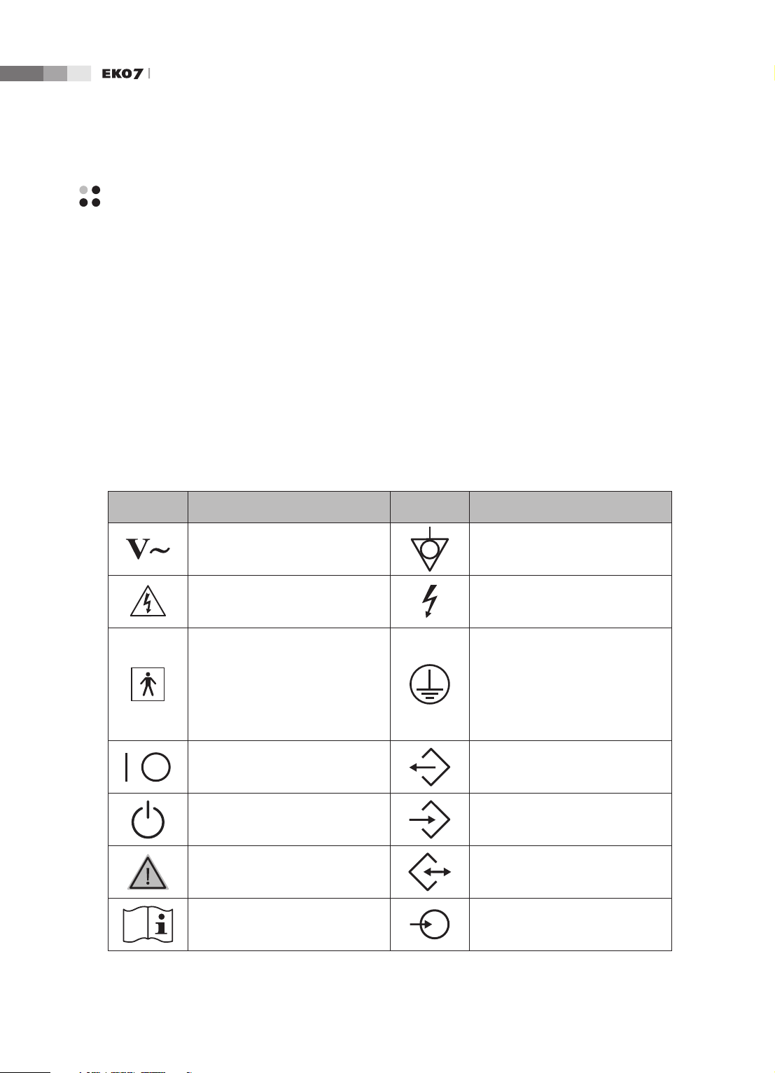
Safety Symbols
The International Electro Technical Commission (IEC) has established a set of symbols for medical
electronic equipment, which classify a connection or warn of potential hazards. The classications and
symbols are shown below.
Symbols Description Symbols Description
AC (alternating current) voltage
source
Identies an equipotential ground.
Indicates a caution for risk of
electric shock.
Indicates dangerous voltages over
1000V AC or over 1500V DC.
Isolated patient connection (Type
BF applied part).
Identies the point where the
system safety ground is fastened
to the chassis. Protective earth
connected to conductive parts
of Class I equipment for safety
purposes.
Power switch (Supplies/cuts the
power for product)
Data Output port
On/Off button Data Input port
Caution Data Input/Output port
Refer to the operation manual
Left and right Audio / Video input
Chapter 1 Safety
1 -
5
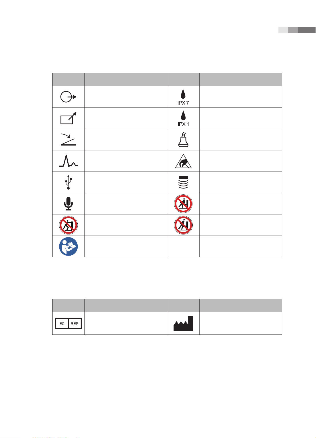
Symbols Description Symbols Description
Left and right Audio / Video output
Protection against the effects of
immersion.
Remote print output Protection against dripping water.
Foot switch connector Probe connector
ECG connector
ESD (Electrostatic discharge)
caution symbol
USB connector Probe connector
Microphone connector
Do not sit on control panel
Do not push the product Do not lean against the product
Follow the operation manual
Symbols
Symbols Description Symbols Description
Authorized Representative In The
European Community
Manufacture :
SAMSUNG MEDISON CO., LTD
1-
6
Operation Manual
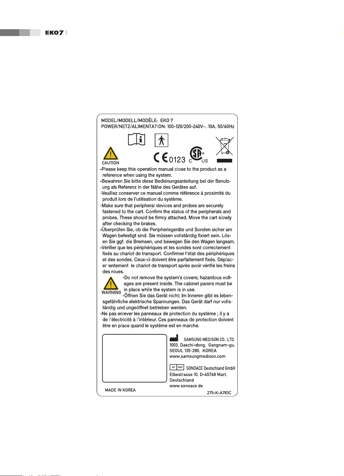
Labels
To protect the system, you may see ‘Warning’ or ‘Caution’ marked on the surface of the product.
[Label 1. ID label]
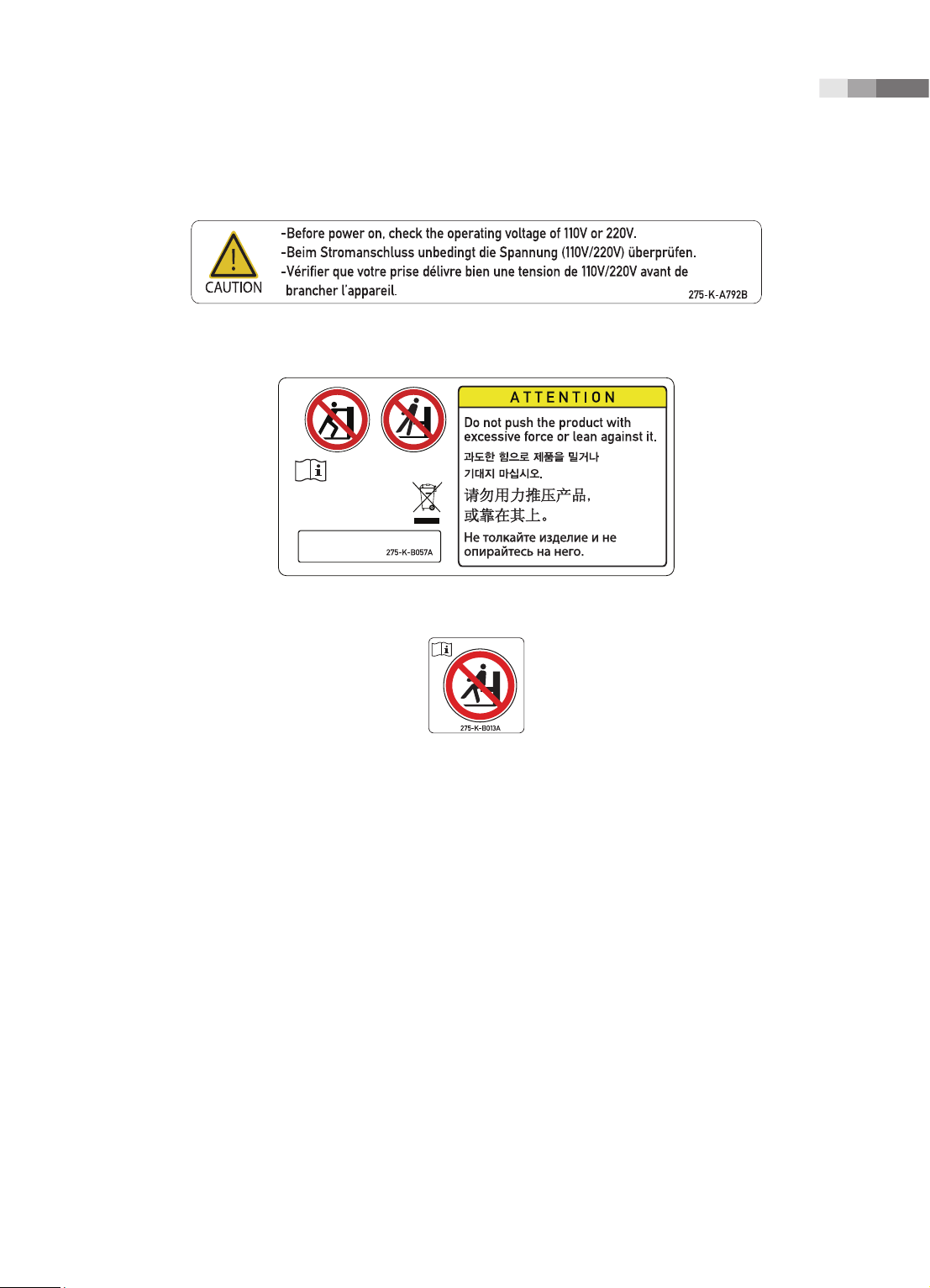
Chapter 1 Safety
1 -
7
[Label 2. Marked below OUTLET]
[Label 3. Safety note for “TIP-OVER” Precaution]
[Label 4. Prohibition of seating on Control panel]
1-
8
Operation Manual
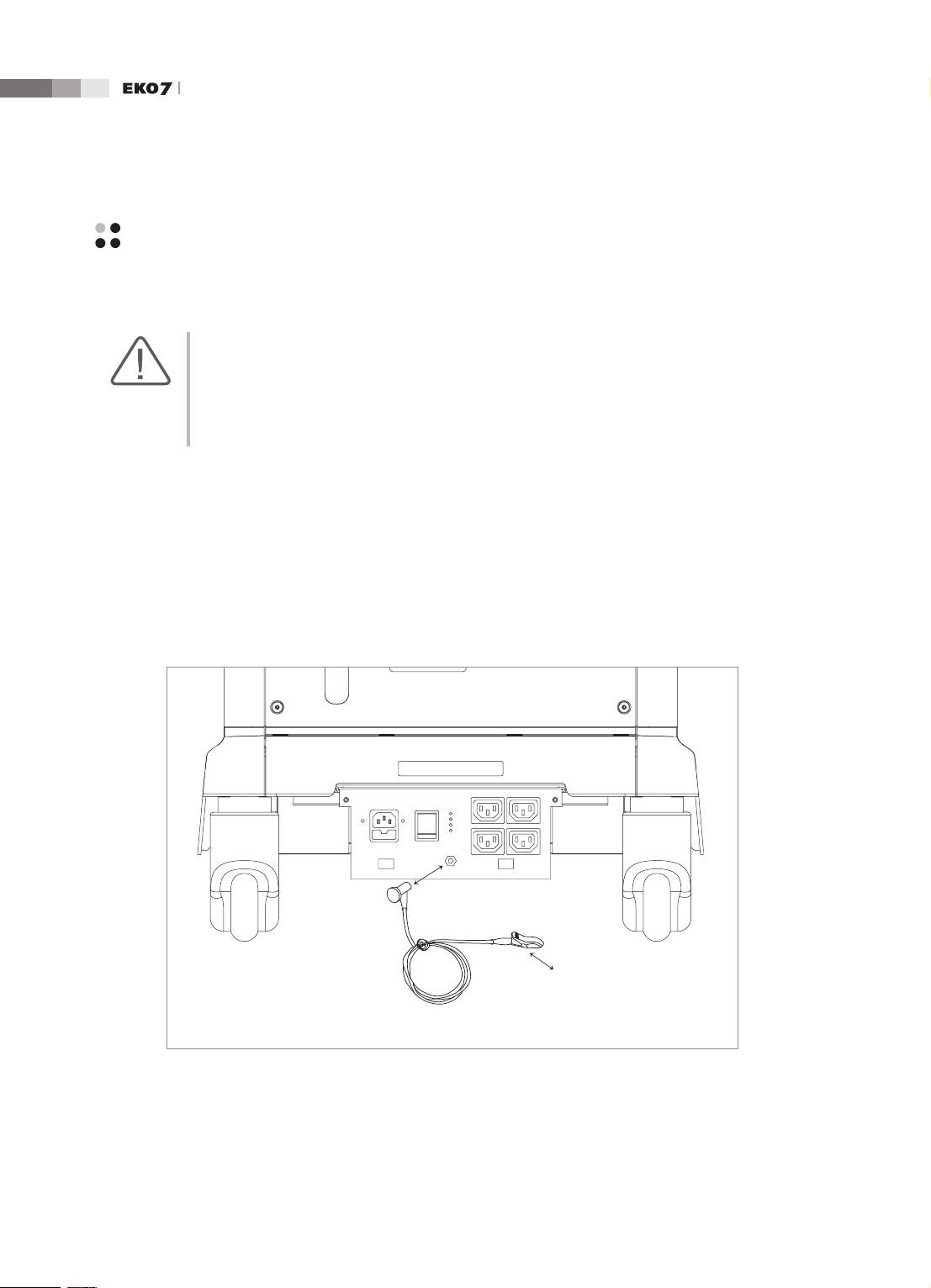
Electrical Safety
This equipment has been veried as a Class I device with Type BF applied parts.
CAUTION:
As for US requirement, the LEAKAGE CURRENT might be measured from a center-tapped circuit
when the equipment connects in the United States to 240V supply system.
To help assure grounding reliability, connect to a “hospital grade” or “hospital only” grounded
power outlet.
Prevention of Electric Shock
In a hospital, dangerous currents are due to the potential differences between connected equipment
and touchable conducting parts found in medical rooms. The solution to the problem is consistent
equipotential bonding. Medical equipment is connected with connecting leads made up of angled
sockets to the equipotential bonding network in medical rooms.
Connection Lead
(Socket)
Equipotential Terminal
Earth in Medical Room
Equipotential Connector
[Figure 1.1 Equipotential bonding]
Chapter 1 Safety
1 -
9
Additional equipment connected to medical electrical equipment must comply with the respective IEC
or ISO standards (e.g. IEC 60950 for data processing equipment). Furthermore all congurations shall
comply with the requirements for medical electrical systems (see IEC 60601-1-1 or clause 16 of the
3 Ed. of IEC 60601-1, respectively). Anybody connecting additional equipment to medical electrical
equipment congures a medical system and is therefore responsible that the system complies with the
requirements for medical electrical systems. Attention is drawn to the fact that local laws take priority
over the above-mentioned requirements. If in doubt, consult your local representative or the technical
service department.
WARNING:
Electric shock may exist result if this system, including and all of its externally mounted recording
and monitoring devices, is not properly grounded.
Do not remove the covers on the system; hazardous voltages are present inside. Cabinet panels
must be in place while the system is in use. All internal adjustments and replacements must be
made by a qualified MEDISON Customer Service Department.
Check the face, housing, and cable before use. Do not use and disconnect the power source, if
the face is cracked, chipped, or torn, the housing is damaged, or if the cable is abraded.
Always disconnect the system from the wall outlet prior to cleaning the system.
All patient contact devices, such as probes and ECG leads, must be removed from the patient
prior to application of a high voltage defibrillation pulse.
Never use the product in proximity to any flammable anesthetic gases (N2O) or oxidizing gases.
There is a risk of explosion.
Avoid places where the system is likely to be difficult to operate the disconnection device.
CAUTION:
The system has been designed for 100-120VAC and 200-240VAC; you should select the input
voltage of printer and VCR. Prior to connecting a peripheral power cord, verify that the voltage
indicated on the power cord matches the voltage rating of the peripheral device.
An isolation transformer protects the system from power surges. The isolation transformer
continues to operate when the system is in standby.
Do not immerse the cable in liquids. Cables are not waterproof.
The auxiliary socket outlets installed on this system are rated 100-120V and 200-240V with
maximum total load of 200W. Use these outlets only for supplying power to equipment that is
intended to be part of the ultrasound system. Do not connect additional multiple-socket outlets
or extension cords to the system.
Do not touch SIP/SOP and the patient simultaneously. There is a risk of electric shock from
leakage current.

1-
10
Operation Manual
ECG-Related Information
WARNING:
This device is not intended to provide a primary ECG monitoring function, and therefore does
not have means of indicating an inoperative electrocardiograph.
Do not use ECG electrodes of HF surgical equipment. Any malfunctions in the HF surgical
equipment may result in burns to the patient.
Do not use ECG electrodes during cardiac pacemaker procedures or other electrical stimulators.
Do not use ECG leads and electrodes in an operating room.
ESD
Electrostatic discharge (ESD), commonly referred to as a static shock, is a naturally occurring
phenomenon. ESD is most prevalent during conditions of low humidity, which can be caused by
heating or air conditioning. During low humidity conditions, electrical charges naturally build up on
individuals, creating static electricity. An ESD occurs when an individual with an electrical energy
build-up comes in contact with conductive objects such as metal doorknobs, le cabinets, computer
equipment, and even other individuals. The static shock or ESD is a discharge of the electrical energy
build-up from a charged individual to a lesser or non-charged individual or object.
CAUTION:
The level of electrical energy discharged from a system user or patient to an ultrasound system
can be significant enough to cause damage to the system or probes.
Always perform the pre-ESD preventive procedures before using connectors marked with the
ESD warning label.
−
Apply anti-static spray on carpets or linoleum.
−
Use anti-static mats.
−
Ground the product to the patient table or bed.
It is highly recommended that the user be given training on ESD-related warning symbols and
preventive procedures.
Chapter 1 Safety
1 -
11
EMI
Although this system has been manufactured in compliance with existing EMI (ElectroMagnetic
Interference) requirements, use of this system in the presence of an electromagnetic eld can cause
momentary degradation of the ultrasound image.
If this occurs often, MEDISON suggests a review of the environment in which the system is being
used, to identify possible sources of radiated emissions. These emissions could be from other
electrical devices used within the same room or an adjacent room. Communication devices such as
cellular phones and pagers can cause these emissions. The existence of radios, TVs, or microwave
transmission equipment nearby can also cause interference.
CAUTION: In cases where EMI is causing disturbances, it may be necessary to relocate this system.
EMC
The testing for EMC(Electromagnetic Compatibility) of this system has been performed according
to the international standard for EMC with medical devices (IEC60601-1-2). This IEC standard was
adopted in Europe as the European norm (EN60601-1-2).
Guidance and manufacturer’s declaration - electromagnetic emission
This product is intended for use in the electromagnetic environment specied below. The customer
or the user of this product should assure that it is used in such an environment.
Emission test Compliance Electromagnetic environment -guidance
RF Emission
CISPR 11
Group 1
The Ultrasound System uses RF energy only for its
internal function. Therefore, its RF emissions are very
low and are not likely to cause any interference in nearby
electronic equipment.
RF Emission
CISPR 11
Class B
The Ultrasound System is suitable for use in all
establishments, including domestic establishments and
those directly connected to the public low-voltage power
supply network that supplies building used for domestic
purpose.
Harmonic Emission
IEC 61000-3-2
Class A
Flicker Emission
IEC 61000-3-3
Complies
1-
12
Operation Manual
Approved Cables, Transducers and Accessories for EMC
■
Approved Cable for Electromagnetic Compliance
Cables connected to this product may affect its emissions;
Use only the cable types and lengths listed below table.
Cable Type Length
VGA Shielded Normal
RS232C Shielded Normal
USB Shielded Normal
LAN(RJ45) Twisted pair Any
S-Video Shielded Normal
Foot Switch Shielded 2.5m
B/W Printer Unshielded Coaxial Normal
MIC Unshielded Any
Printer Remote Unshielded Any
Audio R.L Shielded Normal
VHS Shielded Normal
ECG AUX input Shielded < 3m
Parallel Shielded Normal
■
Approved Transducer for Electromagnetic Compliance
The probe listed in ‘Chapter 9. Probes’ when used with this product, have been tested to comply
with the group1 class B emission as required by International Standard CISPR 11.
■
Approved Accessories for Electromagnetic Compliance
Accessories used with this product may effect its emissions.
CAUTION: When connecting other customer-supplied accessories to the system, such as a remote
printer or VCR, it is the user’s responsibility to ensure the electromagnetic compatibility of the
system. Use only CISPR 11 or CISPR 22, CLASS B compliant devices.
WARNING: The use of cables, transducers, and accessories other than those specified may result in
increased emission or decreased Immunity of the Ultrasound System.

Chapter 1 Safety
1 -
13
Immunity test IEC 60601 Test level Compliance level
Electromagnetic
environment -guidance
Electrotatic
discharge (ESD)
IEC 61000-4-2
±6KV Contact
±8KV air
±6KV Contact
±8KV air
Floors should be wood,
concrete or ceramic tile.
If oors are covered with
synthetic material, the relat-
ive humidity should be at
least 30%.
Electrical fast
transient/burst
IEC 61000-4-4
±2KV
for power supply lines
±1KV
for input/output lines
±2KV
for power supply lines
±1KV
for input/output lines
Mains power quality should
be that of a typical commer-
cial or hospital environment.
Surge
IEC 61000-4-5
±1KV differential mode
±2KV common mode
±1KV differential mode
±2KV common mode
Mains power quality should
be that of a typical commer-
cial or hospital environment.
Voltage
dips, short
interruptions and
voltage variations
on power supply
input lines
IEC 61000-4-11
<5% Uт for 0.5cycle
(>95% dip in Uт)
40% Uт for 5 cycle
(60% dip in Uт )
70% Uт for 25 cycle
(30% dip in Uт)
<5% Uт for 5 s
(<95% dip in Uт )
<5% Uт for 0.5cycle
(>95% dip in Uт)
40% Uт for 5 cycle
(60% dip in Uт )
70% Uт for 25 cycle
(30% dip in Uт)
<5% Uт for 5 s
(<95% dip in Uт )
Mains power quality
should be that of a typical
commer-cial or hospital
environment. If the user
of this product requires
continued operation during
power mains interrup-tions,
it is recommended that this
product be powered from
an uninterruptible power
supply or a battery.
Power frequency
(50/60Hz)
magnetic eld
IEC 61000-4-8
3 A/m 3 A/m
Power frequency magnetic
elds should be at levels
characteristic of a typical
location in a typical
commer-cial or hospital
environment.
NOTE Uт is the a.c. mains voltage prior to application of the test level.
1-
14
Operation Manual
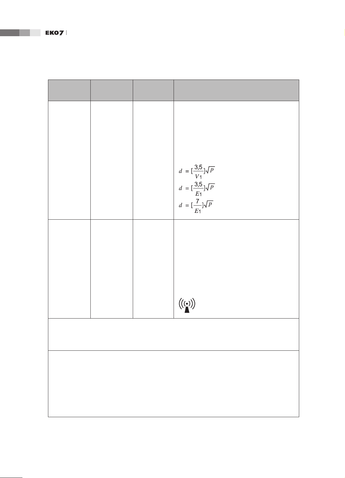
Immunity test
IEC 60601
Test level
Compliance
level
Electromagnetic
environment - guidance
Conducted
RF
IEC 61000-4-
6
3 Vrms
150 kHz
to 80MHz
0.01V
Portable and mobile RF communications
equipment should be used no closer to any part
of the Ultrasound System, including cables, than
the recommended separation distance calculated
from the equation applicable to the frequency of
the transmitter.
Recommended separation distance
80MHz to 800MHZ
800MHz to 2.5GHz
Radiated RF
IEC 61000-4-
3
3 V/m
80 MHz
to 2.5GHz
3V/m
where P is the maximum output power rating
of the transmitter in watts (W) according to the
transmitter manufacturer and d is the recomm-
ended separation distance in meters (m).
Field strengths from xed RF transmitters, as
determined by an electromagnetic site survey,
a
should be less than the compliance level in each
frequency range.
b
Interference may occur in the vicinity of equipment
marked with the following symbol :
NOTE 1) At 80MHz and 800MHz, the higher frequency range applies.
NOTE 2) These guidelines may not apply in all situations. Electromagnetic propagation is affected by
absorption and reection from structures, objects and people.
a
Field strengths from xed transmitters, such as base stations for radio (cellular/cordless) telephones
and land mobile radios, amateur radio, AM and FM radio broadcast and TV broadcast cannot be
predicted theoretically with accuracy. To assess the electromagnetic environment due to xed RF
transmitters, an electromagnetic site survey should be considered. If the measured eld strength in the
location in which the Ultrasound System is used exceeds the applicable RF compliance level above,
the Ultrasound System should be observed to verify normal operation. If abnormal performance is
observed, additional measures may be necessary, such as re-orienting or relocating the Ultrasound
System or using a shielded location with a higher RF shielding effectiveness and lter attenuation.
b
Over the frequency range 150kHz to 80MHz, eld strengths should be less than [V
1
] V/m.
Chapter 1 Safety
1 -
15
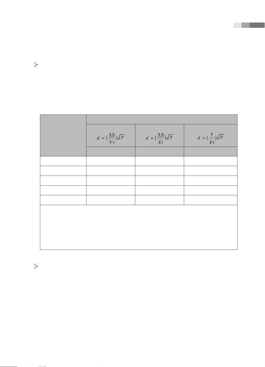
Recommended separation distances between portable and mobile RF
communications equipment and the EKO 7
This product is intended for use in an electromagnetic environment in which radiated RF
disturbances are controlled. The customer or the user of this product can help Prevent
electromagnetic interference by maintaining a minimum distance between portable and mobile RF
communications equipment (transmitters) and this product as recommended below, according to
the maximum output power of the communications equipment.
Rated maximum
output power of
transmitter
[W]
Separation distance according to frequency of transmitter [m]
150kHz to 80MHz
80MHz to 800MHz
800MHz to 2.5GHz
V
1
=0.01Vrms E
1
=3 V/m E
1
=3V/m
0.01 35.00 0.11 0.23
0.1 110.68 0.36 0.73
1 350.00 1.16 2.33
10 1106.80 3.68 7.37
100 3500.00 11.66 23.33
For transmitters rated at a maximum output power not listed above, the recommended separation distance
d in meters (m) can be estimated using the equation applicable to the frequency of the transmitter,
where p is the maximum output power rating of the transmitter in watts (W) according to the transmitter
manufacturer.
NOTE 1) At 80MHz and 800MHz, the separation distance for the higher frequency range applies.
NOTE 2) These guidelines may not apply in all situations. Electromagnetic propagation is affected by
absorption and reection from structures, objects and people.
Electromagnetic environment – guidance
The Ultrasound System must be used only in a shielded location with a minimum RF shielding
effectiveness and, for each cable that enters the shielded location. Field strengths outside the
shielded location from fixed RF transmitters, as determined by an electromagnetic site survey,
should be less than 3V/m.
It is essential that the actual shielding effectiveness and lter attenuation of the shielded location be
veried to assure that they meet the minimum specication.

1-
16
Operation Manual
CAUTION: If the system is connected to other customer-supplied equipment, such as a local area
network (LAN) or a remote printer, Medison cannot guarantee that the remote equipment will work
correctly in the presence of electromagnetic phenomena.
Avoiding Electromagnetic Interference
Typical interference on Ultrasound Imaging Systems varies depending on Electromagnetic
phenomena. Please refer to following table:
Imaging Mode ESD
1
RF
2
Power Line
3
2D
Change of operating
mode, system settings,
or system reset.
Brief ashes in the
displayed or recorded
image.
For sector imaging probes,
white radial bands or
ashes in the centerlines of
the image.
For linear imaging
probes, white vertical
bands, sometimes more
pronounced on the sides of
the image.
White dots, dashes, diagonal
lines, or diagonal lines near
the center of the image.
M
Increase in the image
background noise or white
M mode lines.
White dots, dashes, diagonal
lines, or increase in image
background noise
Color
Color ashes, radial or
vertical bands, increase
in background noise, or
changes in color image.
Color ashes, dots, dashes,
or changes in the color noise
level.
Doppler
Horizontal lines in the
spectral display or tones,
abnormal noise in the audio,
or both.
Vertical lines in the spectral
display, popping type noise in
the audio, or both.
ESD caused by discharging of electric charge build-up on insulated surfaces or persons.
RF energy from RF transmitting equipment such as portable phones, hand-held radios, wireless devices,
commercial radio and TV, and so on.
Conducted interference on powerlines or connected cables caused by other equipment, such as switching
power supplies, electrical controls, and natural phenomena such as lightning.
A medical device can either generate or receive electromagnetic interference. The EMC standards
describe tests for both emitted and received interference.
Medison Ultrasound System do not generate interference in excess of the referenced standards.
An Ultrasound System is designed to receive signals at radio frequency and is therefore susceptible
Loading...