


G2739NR
5. Alignment and Adjustments
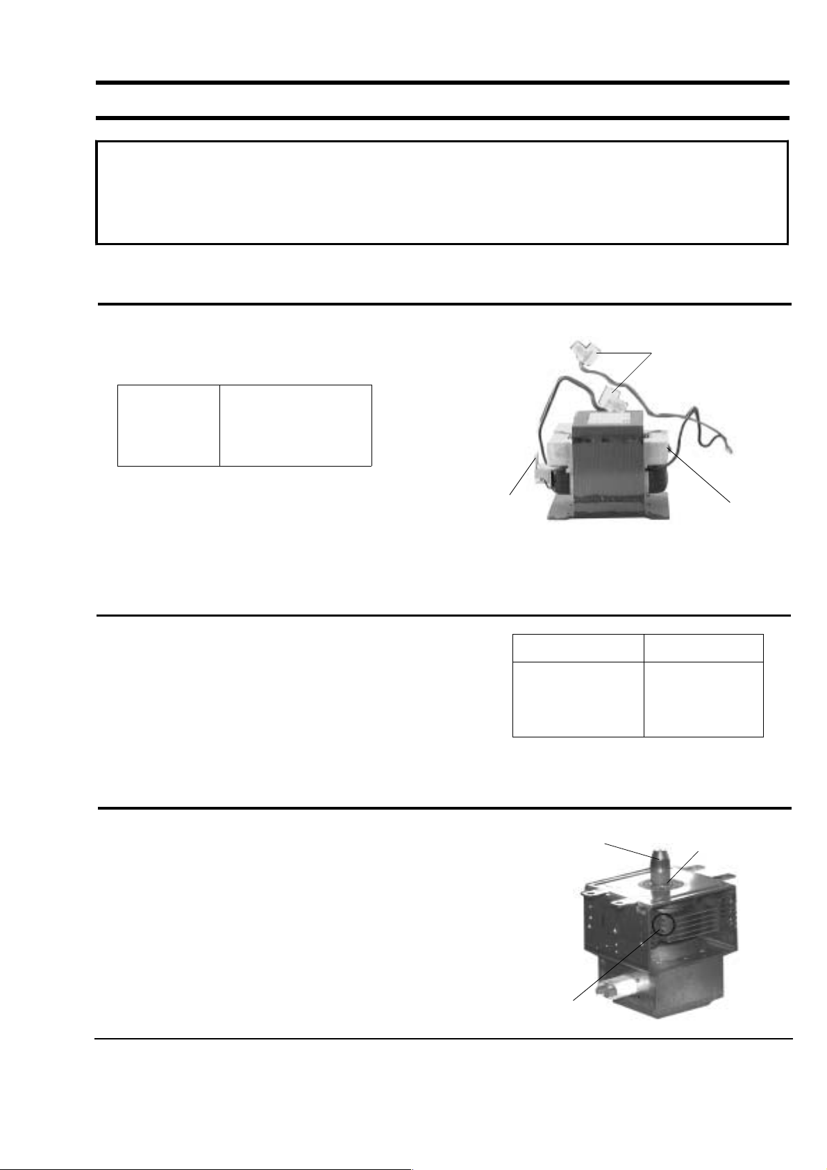
5-1 High Voltage Transformer
1. Remove connectors from the transformer terminals
and check continuity.
2. Normal resistance readings are as follows:
(Room temperature = 20°C)
5-2 Low Voltage Transformer
1.Thelowvoltagetransformerislocatedonthe
control circuit board.
2. Remove the low voltage transformer from the
PCB Ass'y and check continuity.
3. Normal resistor reading is shown in the table.
5-3 Magnetron
1. Continuity checks can indicate only an open
filament or a shorted magnetron. To diagnose an
open filament or shorted magnetron :
2. Isolate the magnetron from the circuit by
disconnecting its leads.
3. A continuity check across the magnetron filament
terminals should indicate one ohm or less.
4. A continuity check between each filament terminal
and magnetron case should read open.
Primary
Terminals
Filament Terminals
Secondary
Terminal
Magnetron Antenna
Gasket Plate
Cooling Fins
PRECAUTION
1. High voltage is present at the high voltage terminals during any cook cycle.
2. It is neither necessary nor advisable to attempt measurement of the high voltage.
3. Before touching any oven components or wiring, always unplug the oven from its power source and
discharge the high voltage capacitor.
Secondary
Filament
Primary
Approx. 151.5
Approx. 0
Approx. 2.5
Terminals Resistance
1~2(Input)
3~4(Output7V)
5~6(Output17V)
1,250
17.4
3.53
5-4 High Voltage Capacitor
1. Check continuity of the capacitor with the meter set at the highest resistance scale.
2. Once the capacitor is charged, a normal capacitor shows continuity for a short time, and then indicates 9M
.
3. A shorted capacitor will show continuous continuity.
4. An open capacitor will show constant 9M
.
5. Resistance between each terminal and chassis should read infinite.
5-5 High Voltage Diode
1. Isolate the diode from the circuit by disconnecting its leads.
2. With the ohm-meter set at the highest resistance scale, measure across the diode terminals. Reverse the
meter leads and read the resistance. A meter with 6V, 9V or higher voltage batteries should be used to
check the front-to back resistance of the diode (otherwise an infinite resistance may be read in both
directions). The resistance of a normal diode will be infinite in one direction and several hundred K
in the
other direction.
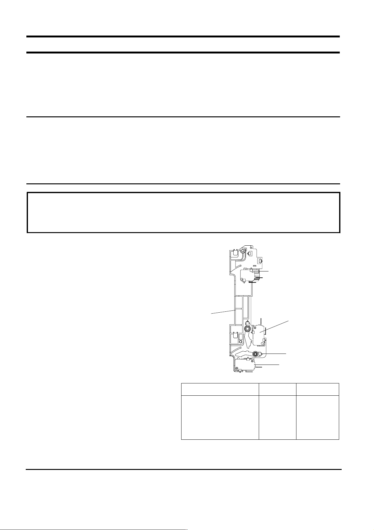
5-6 Adjustment of Primary Switch, Door Sensing Switch and Monitor Switch
1. When mounting Primary switch and Interlock
Monitor switch to Latch Body, consult the figure.
2. No specific adjustment during installation of
Primary switch and Monitor switch to the latch
body is necessary.
3. When mounting the Latch Body to the oven
assembly, adjust the Latch Body by moving it so
that the oven door will not have any play in it.
Check for play in the door by pulling the door
assembly. Make sure that the latch keys move
smoothly after adjustment is completed.
Completely tighten the screws holding the Latch
Body to the oven assembly.
4. Reconnect to Monitor switch and check the
continuity of the monitor circuit and all latch
switches again by following the components test
procedures.
5. Confirm that the gap between the switch
housingandtheswitchactuatorisnomorethan
0.5mm when door is closed.
6.
Interlock Switch Replacement
- When
replacing faulty switches, be sure switch mounting
tabs are not bent, broken or otherwise deficient in
their ability to secure the switches in place.
Door Open Door Closed
Primary switch
Monitor switch (COM-NC)
Monitor switch (COM-NO)
Door Sensing S/W
∞
0
∞
∞
0
∞
0
0
Precaution
For continued protection against radiation hazard, replace parts in accordance with the wiring diagram and be sure to
use the correct part number for the following switches: Primary and secondary interlock switches, and the interlock
monitor switch (replace all together). Then follow the adjustment procedures below. After repair and adjustment, be
sure to check the continuity of all interlock switches and the interlock monitor switch.
Primary Interlock Switch
Interlock
Monitor
Switch
Body Latch
Lever Door(B)
Door Sensing
Switch
 Loading...