

Page 1
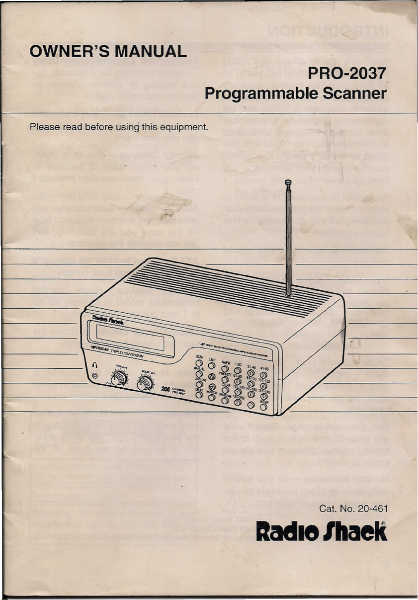
OWNER'S MANUAL
-c
Please read before using this equipment.
-
PRO-2037
Programmable Scanner
1-
F-
•...---
~
~~-.£-
. ~~
~~ ~V~·
~
"''''''~
\0 .,..
@) ~~
0,-'
~'~/
.
"""~
()
"'"
...•
~O~0"" /
@
0011 ~ .
()~o~
~ =-
,
.
.,
CXl
'40~~
lO-
12D
V-
\
Cat. No. 20-461
ltadie/MeIt
Page 2
INTRODUCTION
Your new Radio Shack PRO-2037
Programmable Scanner lets you in on
all the action! This scanner gives you
direct access to more than 31,000 fre-
quencies that include police and fire
departments, aircraft communica-
tions, amateur radio, and ambulance
and transportation services. You can
select up to 200 channels to scan and
you can change your selection at any
time.
The secret to your scanner's ability to
scan so many frequencies is its cus-
tom-designed microprocessor-a tiny,
built-in computer.
Your scanner also has these special
features:
Hyperscan - scans 25 channels per
second and searches 50 frequencies
per second.
Headphones Jack - lets you con-
nect a pair of headphones or an ex-
ternal speaker.
Two-Second Channel Scan Delay
- delays scanning for 2 seconds be-
fore moving to another channel so
you can hear more replies.
Lockout Function - keeps selected
channels from being scanned so you
can skip over them.
Priority Channel - checks a chan-
nel you select every 2 seconds to
keep you from missing important
calls.
AM/FM Mode - automatically se-
lects the most common reception type
for the band you are scanning, and
lets you override the selection.
ATT Switch - reduces the scanner's
sensitivity to strong local signals.
Memory Backup - keeps channel
frequencies stored in memory for up
to 1 hour during a power loss.
Liquid-Crystal Display - shows the
selected channel and frequency.
Triple Conversion Superhetero-
dyne - eliminates any interference
from IF (Intermediate Frequency) im-
ages, so you only hear the selected
frequency.
Ten Channel-Storage Banks - let
you store 20 channels in each of ten
banks to group channels so calls are
easier to identify.
Monitor Memories - let you tempo-
rarily save up to ten channels you lo-
cate during a frequency search.
©
1994 Tandy Corporation.
Radio Shack is a registered trademark used by Tandy Corporation.
All Rights Reserved.
2
Note: Mobile use of this scanner is
unlawful or requires a permit in some
areas. Check the laws in your area.
For your important records, please re-
cord your scanner's serial number in
the space provided. The serial num-
ber is located on the back of the
scanner.
Serial Number: _
Page 3

Your PRO-2037 covers the following
bands:
30 - 50 MHz (VHF Lo)
50 - 54 MHz (6-Meter Ham Band)
118- 136.975 MHz (Aircraft)
137 -144 MHz (Government)
144 - 148 MHz (2-Meter Ham Band)
148 -174 MHz (VHF Hi)
380 - 450 MHz (Ham Radio and Gov-
ernment)
450 - 470 MHz (UHF Lo)
470 - 512 MHz (UHF TV)
806 - 823.9875 MHz (UHF Hi)
849.0125 - 868.9875 MHz (UHF Hi)
894.0125 - 960 MHz (UHF Hi)
FCC NOTICE
Your scanner might cause radio or TV
interference, even when it is operat-
ing properly. To determine whether
your scanner is causing the interfer-
ence, turn off your scanner.Ifthe in-
terference goes away, your scanner is
causing the interference, Try to elimi-
nate the interference by:
• Moving your scanner away from
the receiver
• Connecting your scanner to an out-
let that is on a different electrical
circuit from the receiver,
• Contacting your local Radio Shack
store for help
If
you cannot eliminate the interfer-
ence, the FCC requires that you stop
using your scanner.
This device complies with Part 15 of
FCC Rules.
the following conditions: (1) This de-
vice must not cause harmful interfer-
ence, and (2) this device must accept
any interference received, including
interference that may cause unde-
sired operation.
Operation is subject to
CAUTION: TO REDUCE THE RISK OF ELECTRIC SHOCK,
DO NOT REMOVE COVER (OR BACK). 0 USER·
SERVICEABLE PARTS INSIDE. REFER SERVICI G TO
QUALIFIED SERVICE PERSONNEl.
Warning: To reduce the risk of fire
or electric shock, do not expose
this appliance to rain or moisture.
Ir\
This symbol is intended to
ill
product that presents a risk of electric
shock. Do not open the product's
case.
~ you that important operating
are contained in this owner's manual.
alert you to the presence of
dangerous voltage inside the
~!
This symbol is intended to tell
and maintenance instructions
3
Page 4
CONTENTS
PREPARATION 6
Connecting the Antenna 6
Connecting an Optional Antenna 6
Connecting Power 7
Connecting AC Power 7
Connecting DC Power 8
Resetting and Initializing the Scanner 8
Resetting the Scanner's Display 8
Initializing the Scanner 9
Connecting Headphones 9
Listening Safely 9
Traffic Safety 10
Connecting an External Speaker 10
UNDERSTANDING YOUR SCANNER 11
A Look at the Keyboard 11
A Look at the Display 12
UNDERSTANDING MEMORY 13
Channel-Storage Banks 13
Monitor Memories 13
•
OPERATION 14
Turning On the Scanner/Setting Volume and Squelch 14
Scanning the Channels 14
Turning Channel-Storage Banks On and Off 14
Storing Frequencies 15
Searching For and Temporarily Storing Active Frequencies 15
Limit Search 16
Direct Search 16
Moving a Frequency From a Monitor Memory to a Channel 17
Manually Selecting a Channel 17
4
Page 5
SPECIAL FEATURES 18
Changing the AM/FM Mode 18
Delay 18
Locking Out a Channel 19
Priority 19
Using the ATT Switch 20
A GENERAL GUIDE TO SCANNING 21
Guide to Frequencies 21
National Weather Frequencies 21
Ham Radio Frequencies 21
Birdies 22
Guide to the Action Bands 23
Typical Band Usage 23
Primary Usage 24
Specified Intervals 24
Band Allocation 25
Frequency Conversion 27
TROUBLESHOOTING 28
CARE AND MAINTENANCE 29
SPECIFICATIONS 30
5
Page 6
PREPARATION
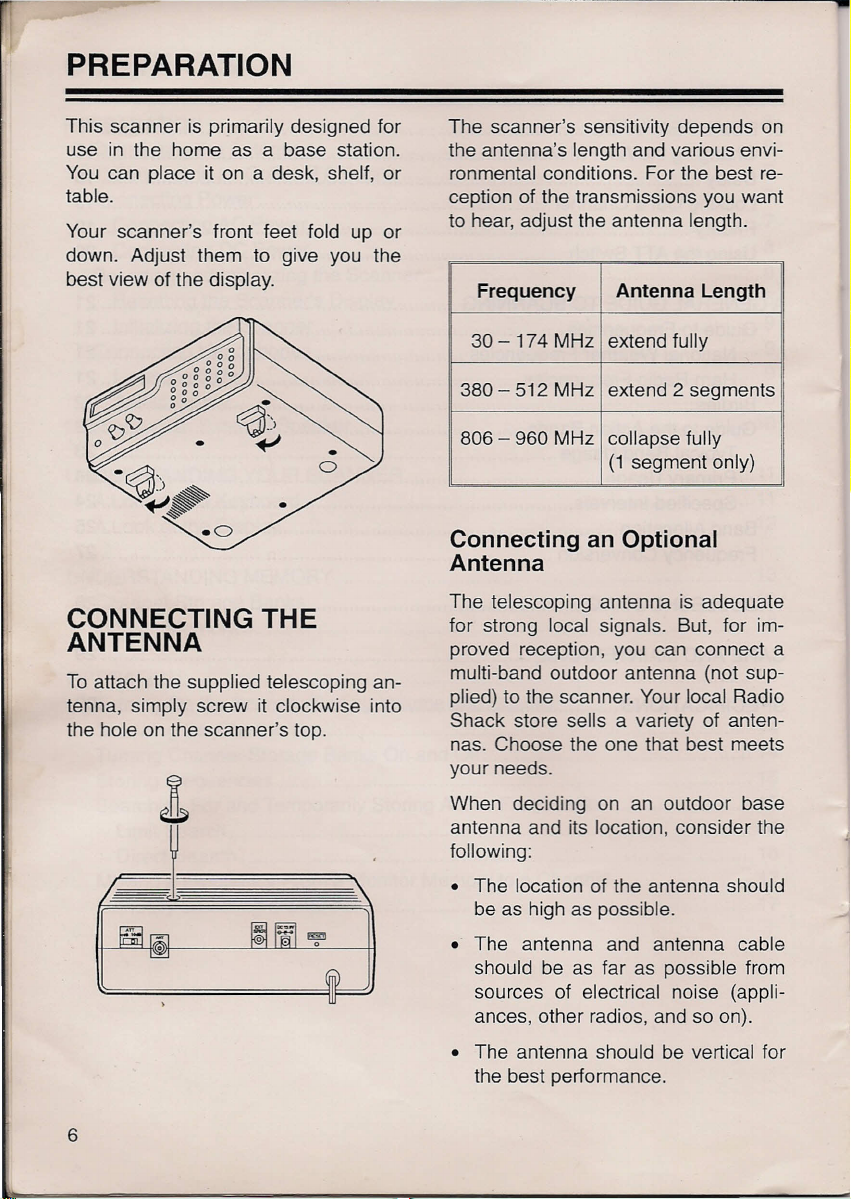
This scanner is primarily designed for
use in the home as a base station.
You can place it on a desk, shelf, or
table.
Your scanner's front feet fold up or
down. Adjust them to give you the
best view of the display.
CONNECTING THE
ANTENNA
To attach the supplied telescoping an-
tenna, simply screw it clockwise into
the hole on the scanner's top.
The scanner's sensitivity depends on
the antenna's length and various envi-
ronmental conditions. For the best re-
ception of the transmissions you want
to hear, adjust the antenna length.
Frequency Antenna Length
30-174 MHz
380 - 512 MHz extend 2 segments
806 - 960 MHz collapse fully
extend fully
(1 segment only)
Connecting an Optional
Antenna
The telescoping antenna is adequate
for strong local signals. But, for im-
proved reception, you can connect a
multi-band outdoor antenna (not sup-
plied) to the scanner. Your local Radio
Shack store sells a variety of anten-
nas. Choose the one that best meets
your needs.
When deciding on an outdoor base
antenna and its location, consider the
following:
• The location of the antenna should
be as high as possible.
• The antenna and antenna cable
should be as far as possible from
sources of electrical noise (appli-
ances, other radios, and so on).
• The antenna should be vertical for
the best performance.
6
Page 7
To connect an optional antenna, always
use 50-ohm coaxial cable, such as RG-
58 or RG-8. For lengths over 50 feet,
use RG-8 low-loss dielectric coaxial ca-
ble. If the coaxial cable's connector
does not fit in the
also need a PL-259-to-BNC antenna
plug adapter, such as Cat. No. 278-
120. Your local Radio Shack store car-
ries a wide variety of coaxial antenna
cable and connectors.
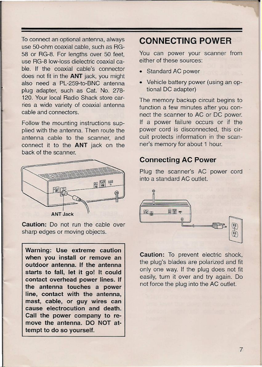
Follow the mounting instructions sup-
plied with the antenna. Then route the
antenna cable to the scanner, and
connect it to the
back of the scanner.
ANT
jack, you might
ANT
jack on the
CONNECTING POWER
You can power your scanner from
either of these sources:
• Standard AC power
• Vehicle battery power (using an op-
tional DC adapter)
The memory backup circuit begins to
function a few minutes after you con-
nect the scanner to AC or DC power.
If a power failure occurs or if the
power cord is disconnected, this cir-
cuit protects information in the scan-
ner's memory for about 1 hour.
Connecting AC Power
Plug the scanner's AC power cord
into a standard AC outlet.
Caution:
sharp edges or moving objects.
Warning: Use extreme caution
when you install or remove an
outdoor antenna. If the antenna
starts to fall, let it go! It could
contact overhead power lines. If
the antenna touches a power
line, contact with the antenna,
mast, cable, or guy wires can
cause electrocution and death.
Call the power company to re-
move the antenna. DO NOT at-
tempt to do so yourself.
Do not run the cable over
Caution:
the plug's blades are polarized and fit
only one way. If the plug does not fit
easily, turn it over and try again. Do
not force the plug into the AC outlet.
To prevent electric shock,
7
Page 8
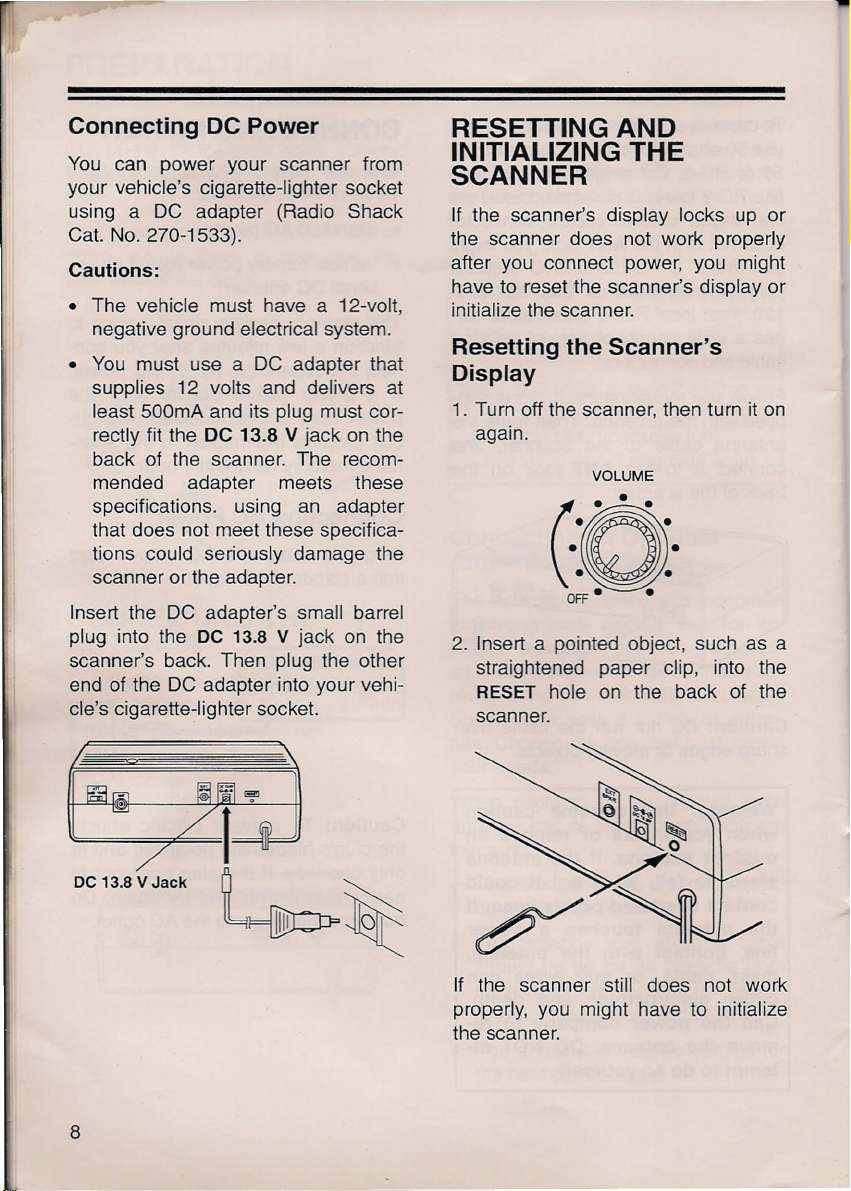
Connecting DC Power
You can power your scanner from
your vehicle's cigarette-lighter socket
using a DC adapter (Radio Shack
Cat. No. 270-1533).
Cautions:
• The vehicle must have a 12-volt,
negative ground electrical system.
• You must use a DC adapter that
supplies 12 volts and delivers at
least 500mA and its plug must cor-
rectly fit the
back of the scanner. The recom-
mended adapter meets these
specifications. using an adapter
that does not meet these specifica-
tions could seriously damage the
scanner or the adapter.
Insert the DC adapter's small barrel
plug into the
scanner's back. Then plug the other
end of the DC adapter into your vehi-
cle's cigarette-lighter socket.
DC 13.8 V
DC
13.8 V jack on the
jack on the
RESETTING AND
INITIALIZING THE
SCANNER
If the scanner's display locks up or
the scanner does not work properly
after you connect power, you might
have to reset the scanner's display or
initialize the scanner.
Resetting the Scanner's
Display
1. Turn off the scanner, then turn it on
again.
VOLUME
2. Insert a pointed object, such as a
straightened paper clip, into the
RESET
scanner.
hole on the back of the
DC 13.8 V Jack
8
If the scanner still does not work
properly, you might have to initialize
the scanner.
Page 9
Initializing the Scanner
Caution:
formation you programmed in the
scanner's memory. Initialize the scan-
ner only when you are sure the scan-
ner is not working properly.
1. Turn off the scanner, then turn it on
again.
This procedure clears all in-
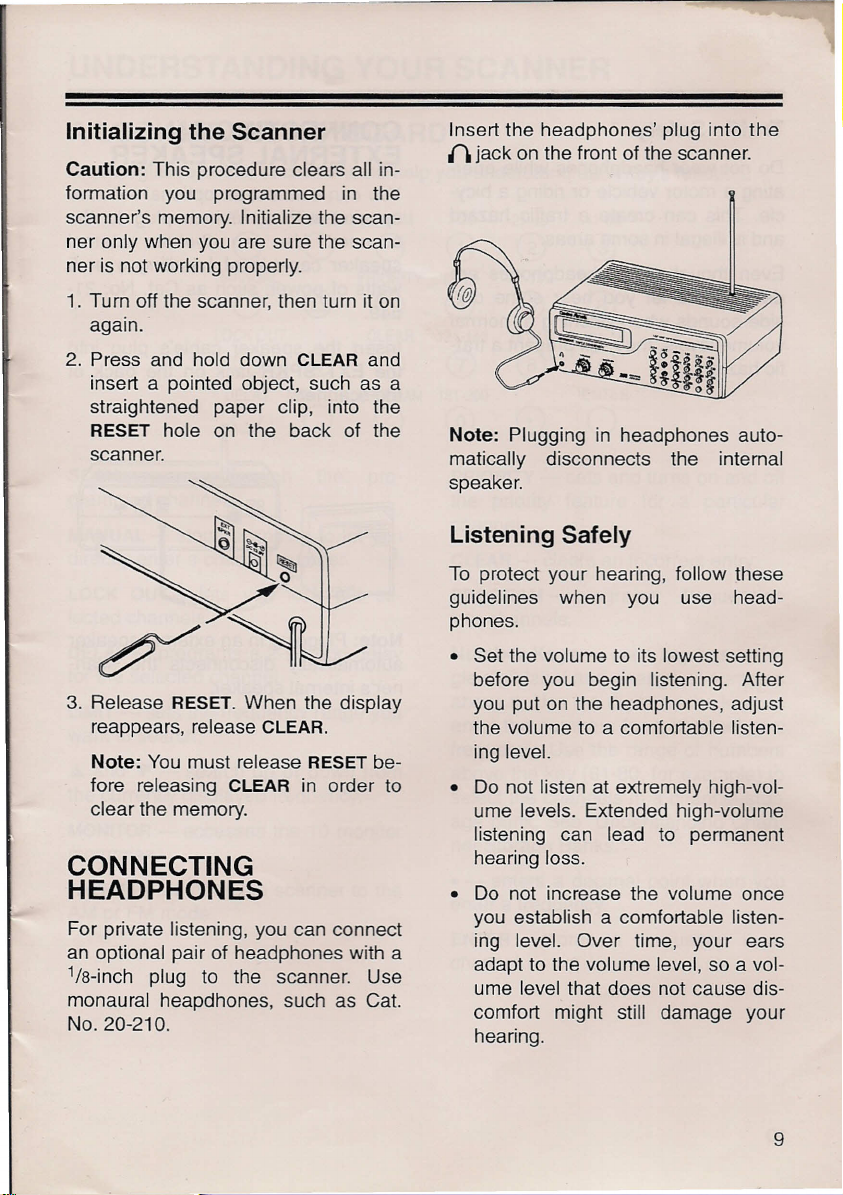
Insert the headphones' plug into the
{\ jack on the front of the scanner.
2. Press and hold down
insert a pointed object, such as a
straightened paper clip, into the
RESET
scanner.
3. Release
reappears, release
Note:
fore releasing
clear the memory.
hole on the back of the
RESET.
You must release
CLEAR
CLEAR
When the display
CLEAR.
in order to
RESET
and
be-
CONNECTING
HEADPHONES
For private listening, you can connect
an optional pair of headphones with a
1
/s-inch plug to the scanner. Use
monaural heapdhones, such as Cat.
No. 20-210.
Note:
matically disconnects the internal
speaker.
Plugging in headphones auto-
Listening Safely
To protect your hearing, follow these
guidelines when you use head-
phones.
• Set the volume to its lowest setting
before you begin listening. After
you put on the headphones, adjust
the volume to a comfortable listen-
ing level.
• Do not listen at extremely high-vol-
ume levels. Extended high-volume
listening can lead to permanent
hearing loss.
• Do not increase the volume once
you establish a comfortable listen-
ing level. Over time, your ears
adapt to the volume level, so a vol-
ume level that does not cause dis-
comfort might still damage your
hearing.
9
Page 10
-
Traffic Safety
Do not wear headphones while oper-
ating a motor vehicle or riding a bicy-
cle. This can create a traffic hazard
and is illegal in some areas.
Even though some headphones are
designed to let you hear some out-
side sounds when listening at normal
volume levels, they still present a traf-
fic hazard.
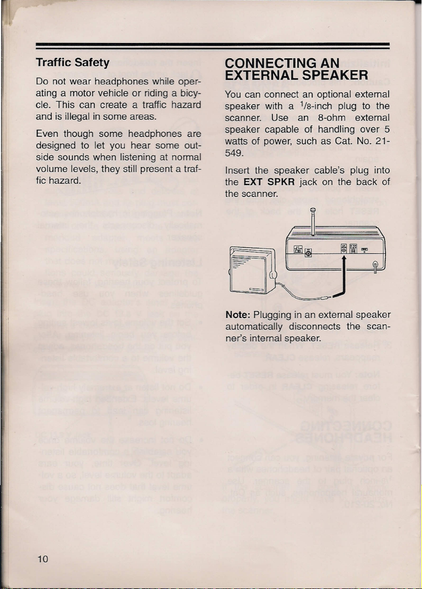
CONNECTING AN
EXTERNAL SPEAKER
You can connect an optional extemal
speaker with a1/s-inch plug to the
scanner. Use an 8-ohm external
speaker capable of handling over 5
watts of power, such as Cat. No. 21-
549.
Insert the speaker cable's plug into
the
EXT SPKR
the scanner.
jack on the back of
= .)
Note:
Plugging in an external speaker
automatically disconnects the scan-
ner's internal speaker.
10
Page 11

UNDERSTANDING YOUR SCANNER
A LOOK AT THE KEYBOARD
A quick glance at this section should help you understand each key's function.
SCAN LIMIT AM/FM
0
MANUAL
0
LOCKOUT
0
DELAY MONITOR PROGRAM
0 0
SCAN - scans through the pro-
grammed channels.
MANUAL - stops scanning to let you
directly enter a channel number.
LOCK OUT - lets you lock out se-
lected channels.
DELAY - programs a 2-second delay
for the selected channel.
LIMIT - sets the frequency range you
want to search.
.•. and T - search up or down from
the currently displayed frequency.
MONITOR - accesses the 10 monitor
memories.
AM/FM - switches the scanner to the
AM or FM mode.
0
@
®
0
PRIORITY
0
CLEAR
0
0
1-20
CD
61-80
8)
121-140
0
181-200
@
the priority feature for a particular
channel.
21-40
@ @
81-100
®
141-160
® ®
(0
PRIORITY - sets and turns on and off
CLEAR - clears an incorrect entry.
PROGRAM - programs frequencies
into channels.
Number Keys - each key has a sin-
gle digit label and a range of numbers
above it. Use the digits on the keys to
enter the numbers for a channel or a
frequency. Use the range of numbers
above the key (61-80, for example) to
select the channels in a channel-stor-
age bank. See "Understanding Chan-
nel-Storage Banks."
• - enters a decimal point when you
enter a frequency.
ENTER - stores a frequency in a
channel.
41-60
101-120
@
161-180
ENTER
0
11
Page 12

A LOOK AT THE DISPLAY
The display has several indicators that show the scanner's current operating
mode. A quick look at the display will help you understand how to operate your
scanner.
MANUAL MONITOR 1 2 3 4 5 6 7 8 9 10
SCAN BANK ---------- DELAY
SEARCH
PRIORITY ~
i' .-,
ri.-, .-,.-,n.-,n.-,-
_ _ _ _ _ _ _' _ _ I
LI LI LI CHLI LI LI LI LI LI 0 AM
.
l
F M
PROGRAM
LOCK-OUT
MANUAL -
ally select a channel.
SCAN -
channels.
SEARCH -
search
search
also appear to indicate the search di-
rection.
PRIORITY -
turn on the priority channel feature.
P -
appears when the scanner is set
to the priority channel.
MONITOR -
ten to a monitor memory.
BANK -
cator show which memory banks are
turned on for scanning.
appears when you manu-
appears when you scan
appears during a limit
(-L-
also appears) or a direct
(-d-
also appears).Aand
appears when you
appears when you lis-
bars to the right of this indi-
CH - appears
to show which of the scanner's 200
channels it is tuned to.
FMorAM -
ner is set to the
FMorAM
T
lected the mode.
DELAY -
stops at a channel you programmed
for a 2-second delay.
PROGRAM -
gram frequencies into the scanner's
channels.
LOCK-OUT -
lock out a channel or manually select
a locked-out channel.
with a number (1-200)
shows whether the scan-
FM or AM
flashes, you manually se-
appears when the scanner
appears when you pro-
appears when you
mode.
If
12
Page 13

UNDERSTANDING MEMORY
You can store frequencies into either
a permanent memory location, called
a channel, or a temporary memory lo-
cation, called a monitor memory. You
can store up to 200 channels and 10
monitor memories.
CHANNEL-STORAGE
BANKS
To make it easier to identify and se-
lect the channels you listen to most
often, channels are divided into 10
channel-storage banks (1 to 10) of 20
channels each. You can use each
channel-storage bank to group fre-
quencies, such as those used by the
police department, fire department,
ambulance services, or aircraft (see
"Guide to the Action Bands").
For example, there might be three or
four police departments in your area,
each using several different frequen-
cies. Additionally, there might be other
law enforcement agencies such as
state police, county sheriffs, or SWAT
teams that use their own frequencies.
You could program all law enforce-
ment frequencies starting with Chan-
nel 1 (the first channel in Bank 1),
then program the fire department,
paramedic, and other public safety
frequencies starting with Channel 21
(the first channel in Bank 2).
MONITOR MEMORIES
The scanner also has 10 monitor
memories. You can use these memo-
ries to temporarily store frequencies
while you decide whether or not to
save them in channels. This is handy
for quickly storing an active frequency
when you search through an entire
band.
Notes:
• To store a frequency into a monitor
memory, you must perform a limit
or direct search. See "Searching
For and Temporarily Storing Active
Frequencies."
• You can select monitor memories
manually, but you cannot scan
them. See "Using Monitor Memo-
ries."
13
Page 14

OPERATION
TURNING ON THE
SCANNER/SETTING
VOLUME AND SQUELCH
1. Turn
2. Turn
3. Slowly turn
Note:
wanted weak transmissions, turn
SQUELCH
scanner's sensitivity to these signals.
If you want to listen to a weak or dis-
tant station, tum
clockwise.
SQUELCH
wise.
VOLUME
hear a hissing sound. The scanner
automatically scans all 10 banks.
then leave it set to a point just after
the hissing stops.
If the scanner picks up un-
clockwise to decrease the
fully counterclock-
SQUELCH
clockwise until you
VOLUME
SQUELCH
SQUELCH
clockwise,
counter-
SCANNING THE
CHANNELS
To begin scanning the channels or to
start scanning again after monitoring
a channel, press
scans either up or down through all
non-locked channels in the active
banks (see "Locking Out Channels").
To change the scanning direction,
pressAor
Note:
An improper
might keep your scanner from scan-
ning. See ''Turning on the Scan-
ner/Setting Volume and Squelch."
T.
SCAN.
SQUELCH
The scanner
setting
TURNING
CHANNEL-STORAGE
BANKS ON AND OFF
When you first turn on the scanner,
the scanner scans all ten channel-
storage banks. As the scanner scans
a bank, the bar under the bank's num-
ber flashes.
To turn off banks while scanning,
press the bank's number key until the
bar under the bank's number disap-
pears. The scanner does not scan
any of the stored channels within
banks you have turned off.
Notes:
• You cannot turn off all banks.
There must be at least one active
bank.
14
• You can manually select any chan-
nel in a bank, even if the bank is
turned off.
Page 15

To tum on banks while scanning,
press the bank's number key until the
bar appears under the bank's number.
3. Using the number keys, enter the
frequency you want to store in that
channel.
STORING
FREQUENCIES
Good references for active frequen-
cies are Radio Shack's "Police Call
Radio Guide Including Fire and Emer-
gency Services," "Official Aeronautical
Frequency Directory," and "Maritime
Frequency Directory." We update
these directories every year, so be
sure to get a current copy. See also
"Guide to the
manual.
If you do not have a reference to fre-
quencies in your area, you can use a
limit or direct search to find a trans-
mission.
You can store up to 200 frequencies
into your scanner's channels. Follow
these steps to store frequencies.
1. Press
number you want to program.
MANUAl. 12345678010
Action
MANUAl.
BANK -
'" riririrtrtrt
-I( CHLILlLI.LILlLIO
Enter the channel
Bands" in this
4. Press
ENTER
to store the fre-
quency.
1 2 3 4 5 6 7 8 9 10
BA* -
In u: ir r ri
ILICH 10 1.0:ILlO
FM
PROGRAM
If you make a mistake in Step 3,
Error
Press
appears on the display.
CLEAR
and repeat Steps 3
and 4.
5. Repeat Steps 1-4 to program more
channels or Steps 2-4 if you want
to program the next channel in se-
quence.
SEARCHING FOR AND
TEMPORARILY
STORING ACTIVE
FREQUENCIES
You can search for frequencies using
either of the following methods, then
temporarily store the frequencies in
monitor memories.
• Limit search (within a range of fre-
quencies you select)
2. Press
PROGRAM. PROGRAM
pears on the display.
1 2 3 4 5 6 7 8 9 10
BANK -
,n
ILl CHLlLILI.LILILIO
ririrvnrm
ap-
PROGRAM
• Direct search (any range of fre-
quencies before or after a fre-
quency you select)
15
Page 16

Limit Search
Limit search lets you search for active
frequencies within a range you select,
so you can choose which ones you
want to store.
Note: You can use the scanner's de-
lay feature while using limit search
(see "Delay").
6. Press .• to search from the lower
to the upper limit, or press ..•. to
search from the upper to the lower
limit.
-L-,
SEARCH,
and .• or ..•.
appear on the display.
MONITOR 1 2 3 4 5 6 7 8 • 10
X
I,-,nn"
10. U U LI [] AM
Follow these steps to search for ac-
tive frequencies.
1. Press
PROGRAM,
then
LIMIT.
Lo
appears on the display.
Lo
rir»nFM
_ILI.LI U LI
PROGRAM
u
:J""
n
2. Using the number keys, enter the
lower limit of the frequency range.
Notes: If you enter an invalid fre-
quency in Step 2 or 4,
Error
ap-
pears on the display. Simply repeat
the step.
3. Press
ENTER,
then
LIMIT. Hi
ap-
pears on the display.
CI C
nnn
"n
FM
:-1,
_I U U.LI U LI
PROGRAJ,I
u
4. Using the number keys, enter the
upper limit of the frequency range.
5. Press
ENTER.
7. When the scanner stops on a
transmission, press
MONITOR
store the frequency in the current
monitor memory, or press .• or ..•.
to continue the search.
Direct Search
When the scanner is stopped on a
frequency, you can search up or down
from the current displayed frequency
to find more frequencies you want to
store.
Note: You can use the scanner's de-
lay feature while using direct search
(see "Delay").
1. Press
MANUAL 1 2 3 4 5 I 7 8 • 10
2. Use the number keys to enter the
MANUAL
BANK
""-1
-,,: CHLI U U.LI
or
PROGRAM.
nnnnn"
'-.1
U []
frequency you want to start the
search from. Or, use the number
keys to enter the channel number
containing the starting frequency.
Then press
MANUALorPROGRAM.
to
16
Page 17

3. Press .•. to search up or ..•• to
search down from the frequency.
-d-, SEARCH,
and .•. or ..•.appear
on the display.
MONITOR 1 2 3 4 5 6 7 8 9 10
SEARCH! - d-
X
"_'lInnnn
I II.LILIUu
FM
4. When the scanner finds an active
frequency, it stops searching. To
save the frequency into a current
monitor memory, press
MONITOR.
The bar under the memory number
stops flashing.
5. Press .•. or ..•• again to continue
searching for more active frequen-
cies.
MOVING A FREQUENCY
FROM A MONITOR
MEMORY TO A CHANNEL
1. Press
MANUAL
2, Use the number keys to enter the
MANUAL.
1 2 3 4 5 6 7 8 9 10
BANK -
t "
r,nr,nnn
-,e
CHLILILI,LIUu[J
channel number where you want to
store the monitor frequency. Then
press
PROGRAM.
1 2 3 4 5 6 7 8 8 10
BANK -
In, rirtririrn
ILl ICHUULI,LILIU[J
Pl!0GRAM
3. Press
MONITOR
and the number of
the monitor memory that has the
frequency you want to store.
MONITOR
and the frequency ap-
pear on the display,
MONITOR
1 2 3 4 5 6 7 8 8 10
-
IlIlI ,
C.
I'nFM Pl!0GIIAM
4. Press
ENTER.
I I 1,1_'Uu
The scanner stores
the frequency into the channel.
MANUALLY SELECTING
A CHANNEL
You can continuously monitor a spe-
cific channel without scanning. This is
useful if you hear an emergency
broadcast on a channel and do not
want to miss any details (even though
there might be periods of silence) or if
you want to monitor a locked-out
channel.
To select a channel, just press
UAL.
Enter the channel number, and
press
MANUAL
again. Or, if the scan-
ner is scanning and stops at the de-
sired channel, just press
one time. Pressing
MANUAL
tional times makes the scanner step
through the channels.
MAN-
MANUAL
addi-
17
Page 18

SPECIAL FEATURES
CHANGING THE AM/FM
MODE
We designed your scanner to auto-
matically select the most common re-
ceive
mode for each frequency range.
The default settings are:
FREQUENCY RECEIVE
(MHz) MODE
30.000 - 54.000
118.000 - 136.975 AM
137.000 -174.000 FM
380.000 - 512.000 FM
806.000 - 960.000
Although the preset mode is correct in
most cases, some ham radio and mili-
tary aircraft broadcasts do not receive
in the default mode. When the scan-
ner is not set to the correct
mode, the broadcast might sound
weak or distorted.
To change the mode, press
AMorFM
you override the default mode.
MANUAL 1 2 3 4 5 6 7 8 9 10
blinks on the display when
BANK -
,,-, -,,-,-,r
,:' 'CH:,,:,e.:,uL'[]>M:
FM
FM
receive
AMlFM.
rn
If you press
direct search, the scanner no longer
uses the default AM/FM mode for
each frequency. The scanner keeps
searching for frequencies in the se-
lected mode and
the display.
the mode of a frequency is the same
as the default setting. To return to the
default settings, press
holding down
LOCK OUT CLEAR 121·140
AMlFM
AM
CLEAR.
SCAN LIMIT AMlFM 1·20
o
MANUAL PRIORITY 61·80
o
o
DELAY MONITOR PROGRAM 181·200
o
during a limit or
AMorFM
or
FM
0
CYG)
@
0 8)
®
CY0
0 0
blinks on
blinks
AMlFM
@
even
while
DELAY
Many agencies use a two-way radio
system that might
tween a query and a reply. Your scan-
ner's delay feature waits for 2
seconds after each transmission
while scanning or searching.
To program a 2-second delay for any
channel while scanning, manually se-
lect the channel and press
til
DELAY
When your scanner stops on the
channel, it waits for 2 seconds after
each transmission before it resumes
scanning.
appears on the display.
have
a pause be-
DELAY
un-
if
18
MANUAl 1 2 3 4 5 8 7 8 9 10
BANK - DElAY
:r:r "
L L
CH ,-,
fur
-'.:'ULlu
ru»
n
FM
Page 19

To program a 2-second delay for any
active frequency while searching,
press
DELAY
the display. When your scanner stops
on a frequency, it waits for 2 seconds
after each transmission before it re-
sumes searching.
To turn off the programmed delay on
any active channel, press
while the channel is still active.
LAY
disappears from the display.
until
DELAY
appears on
DELAY
DE-
PRIORITY
The priority feature lets you scan
through the programmed channels
and still not miss an important or in-
teresting call on a specific channel. To
program a stored channel as the pri-
ority channel, press
desired channel number, and then
PRIORITY.
Note: You can only select one chan-
nel as the priority channel.
PROGRAM,
the
LOCKING OUT A
CHANNEL
You can scan channels faster by lock-
ing out those that have a continuous
transmission, such as a weather
channel.
To lock out a channel while scanning,
press
stops on the channel. To lock out a
channel manually, manually select the
channel and press
LOCK-OUT
To remove the lockout from a chan-
nel, manually select the channel and
press
appears from the display.
LOCK OUT
LOCK OUTsoLOCK-OUT
Notes:
• You can still manually select
locked-out channels.
• You cannot lock out all channels.
There must be at least one active
channel in a bank.
when the scanner
LOCK OUT
appears on the display.
until
dis-
To turn on the priority feature, press
PRIORITY
ITY
scanner checks the priority channel
every 2 seconds, and stays on the
channel if there is activity. P appears
to the left of the display whenever the
scanner is set to the priority channel.
To turn off the priority feature, press
PRIORITY
ORITY
during scanning.
appears on the display. The
during scanning until
disappears from the display.
PRIOR-
PRI-
19
Page 20

USING THE ATT SWITCH
You can set
terference or noise caused by signals
from a strong local broadcast, or to
OdB
to increase the reception of weak
signals
ATTto1Oc;IB
ATT
OdB 10dB
to reduce in-
ILJIIIIlJI
Note:
your scanner might not receive weak
signals.
With the switch set to
10dB,
20
Page 21

A GENERAL GUIDE TO SCANNING
Reception of the frequencies covered by your scanner is mainly "Iine-of-sight."
That means you usually cannot hear stations that are beyond the horizon.
During the summer months, you might be able to hear stations in the 30 - 50
MHz range located several hundred or even thousands of miles away. This is be-
cause of summer atmospheric conditions. This type of reception is unpredictable
but often very interesting!
GUIDE TO FREQUENCIES
National Weather Frequencies
161.650 MHz 162.425 MHz 162.475 MHz
161.775 MHz
162.400 MHz
162.440 MHz
162.450 MHz
162.500 MHz
162.525 MHz
162.550 MHz
163.275 MHz
Ham Radio Frequencies
Ham radio operators often broadcast emergency information when other means
of communication break down.
The following chart shows the voice frequencies that you can monitor.
Wavelength Voice
(meters) (MHz)
6-meter 50.100 54.000
2-meter
70-cm
144.100 148.000
420.000
450.000
21
Page 22

BIRDIES
Birdies are frequencies your scanner uses when it operates. These operating fre-
quencies might interfere with broadcasts on the same frequencies. If you program
one of these frequencies, the scanner locks up and you hear only noise on that
frequency.
If the interference is not severe, you might be able to rotate SQUELCH clockwise
to cut out the birdie. The most common birdies to watch for are listed below.
Birdie Frequencies:
32.100 MHz
32.250 MHz
42.975 MHz
44.085 MHz
48.185 MHz
52.400 MHz
Note: Depending on the temperature of some of the scanner's internal compo-
nents, you might hear birdies on frequencies slightly above or below the frequen-
cies listed here.
150.150 MHz
155.500 MHz
166.200 MHz
171.250 MHz
171.550 MHz
400.400 MHz
429.050 MHz
434.400 MHz
450.450 MHz
479.100 MHz
489.290 MHz
504.125 MHz
810.150 MHz
820.650 MHz
915.400 MHz
944.050 MHz
949.400 MHz
22
Page 23

GUIDE TO THE ACTION BANDS
Typical Band Usage
VHF Band (30.00-300.0 MHz)
Low Range
6-Meter Amateur
Aircraft
U.S. Government
2-Meter Amateur
High Range
UHF Band (300.00 MHz-3.0 GHz)
Military Aircraft
U. S. Government
70-Centimeter Amateur
Low Range
FM-TV Audio Broadcast, Wide Band
Public Service
Conventional Systems
ConventionalfTrunked Systems
Trunked Systems
Public Safety
High Range
33-Centimeter Amateur
Private Trunked
General Trunked
Fixed Services
Studio-to-Transmitter Broadcast Links
Private Fixed Services, Paging
(30.00 - 50.00 MHz)
(50.00 - 54.00 MHz)
(108.00 - 136.00 MHz)
(137.00 -144.00 MHz)
(144.00 -148.00 MHz)
(148.00 - 174.00 MHz)
(380.00 - 384.00 MHz)
(406.00 - 450.00 MHz)
(420.00 - 450.00 MHz)
(450.00 - 470.00 MHz)
(470.00 - 512.00 MHz)
(806.00 - 823.98 MHz)
(851.00 - 856.00 MHz)
(856.00 - 861.00 MHz)
(861.00 - 866.00 MHz)
(866.00 - 869.00 MHz)
(894.01 - 902.00 MHz)
(902.00 - 928.00 MHz)
(935.00 - 940.00 MHz)
(940.00 - 941.00 MHz)
(941.00 - 944.00 MHz)
(944.00 - 952.00 MHz)
(952.00 - 960.00 MHz)
23
Page 24

Primary Usage
As a general rule, most of the radio activity is concentrated on the following fre-
quencies:
VHF Band
Activities Frequencies
Government, Police, and Fire 153.785 - 155.980 MHz
Emergency Services
158.730 - 159.460 MHz
Railroad
UHF Band
Activities Frequencies
Land-Mobile Paired Frequencies 450.000 - 470.000 MHz
Base Stations 451.025 - 454.950 MHz
Mobile Units 456.025 - 459.950 MHz
Relay Repeater Units 460.025 - 464.975 MHz
Remote Control Stations 465.025 - 469.975 MHz
Note: Remote control stations and mobile units operate at 5 MHz higher than
their associated base stations and relay repeater units.
160.000 - 161.900 MHz
Specified Intervals
Frequencies in different bands are accessible only at specific intervB:ls.For example:
Band Type Specified Interval
VHF, HAM, and Government 5.0 kHz steps
All Others 12.5 kHz steps
Aircraft
25.0 kHz steps
Note: Your scanner automatically rounds the entered frequency down to the clos-
est valid frequency. For example, if you try to enter a frequency of 151.473, your
scanner accepts it as 151.470.
24
Page 25

BAND ALLOCATION
To help decide which frequency ranges to scan, use the following listing of the
typical services that use the frequencies your scanner receives. These frequen-
cies are subject to change, and might vary from area to area. For a more com-
plete listing, refer to the "Police Call Radio Guide including Fire and Emergency
Services," available at your local Radio Shack store.
Abbreviations
AIR Aircraft
BIFC Boise (10) Interagency Fire Cache
BUS Business
CAP Civil Air Patrol
CR Citizens Band
CCA Common Carrier
CSB Conventional Systems
CTSB ConventionaVTrunked Systems
FIRE Fire Department
HAM Amateur (Ham) Radio
GOVT Federal Govemment
GMR General Mobile Radio
GTR General Trunked
IND Industrial Services
(Manufacturing, Construction, Farming,
Forest Products)
MAR Military Amateur Radio
MARI Maritime Limited Coast
(Coast Guard, Marine telephone,
Shipboard Radio, Private stations)
MARS Military Affiliate Radio System
MED ...............•............... Emergency/Medical Services
MIL U.S. Military
MOV Motion PictureNideo Industry
NEW New Mobile Narrow
NEWS Relay Press (Newspaper reporters)
OIL Oil/Petroleum Industry
PFSP Private Fixed Services/Paging
POL Police Department
PUB Public Services
(Public Safety, Local Government,
Forestry Conservation)
PSB Public Safety
PTR Private Trunked
ROAD Road & Highway Maintenance
RTV RadiolTV Remote Broadcast Pickup
TAXi Taxi Services
TELB Mobile Telephone
(Aircraft, Radio Common Carrier,
TELC Cordless Phones
TELM Telephone Maintenance
TOW Tow Trucks
TRAN Transportation Services
(Trucks, Tow Trucks, Buses, Railroad, Other)
TSB Trunked Systems
TVn FM-TV Audio Broadcast
USXX Government Classified
UTIL Power & Water Utilities
WTHR Weather
Very High Frequency (VHF) - (30 MHz - 300 MHz)
Low Band
(29.7-50
MHz - in5kHz steps)
30.550
30.580-31.980
32.000-32.990
33.020-33.980
34.010-34.990
35.020-35.980
36.000-36.230
36.250
36.270-36.990
37.020-37.980
38.000-39.000
39.020-39.980
40.000-42.000
42.020-42.940
42.960-43.180
43.220-43.680
43.700-44.600
44.620-46.580
46.600-46.990
47.020-47.400
47.420
47.440-49.580
49.610-49.990
Landline companies)
GOVT, MIL
IND, PUB
GOVT, MIL
US, IND, PUB
GOVT,MIL
BUS, PUB, IND, TELM
GOVT, MIL
0il Spill Clean up
GOVT, MIL
PUB, IND
GOVT, MIL
PUB
GOVT, MIL, MARl
POL
IND
TELM, IND, PUB
TRAN
POL, PUB
GOVT, TELC
PUB
American Red Cross
IND, PUB
MIL, TELC
25
Page 26

6-Meter Amateur Band - (50--54 MHz)
50.00--54.00 HAM
Aircraft Band (108-136 MHz)
108.000--121.490 AIR
121.500 AIR Emergency
121.51 0--136.000 AIR
U.S. Govemment Band (138-144 MHz)
137.000--144.000 GOVT, MIL
2-Meter Amateur Band (144-148 MHz)
144.000--148.000......................... . HAM
VHF-Hi BAND (148-174 MHz)
148.050--150.345 CAP, MAR, MIL
150.775-150.790 MED
150.815-150.965 TOW
150.980 Oil Spill Clean up
150.995-151.130 ROAD
151.145-151.475 .........•...... . POL
151.490--151.955 IND, BUS
151.985 _ TELM
152.0075 MED
152.030--152.240 ...................•............................. TELB
152.270--152.465 IND, TAXI
152.480 BUS
152.510--152.840 TELB
152.870--153.020 IND,MOV
153.035-153.725 IND, OIL, UTIL
153.740--154.445 PUB, FI RE
154.490--154.570..................... .. IND, BUS
154.585 Oil Spill Clean up
154.600--154.625 BUS
154.655-156.240 .....•............ MED, ROAD, POL, PUB
156255 , OIL
156.275-157.425 MARI
157.450 MED
157.470--157.515 TOW
157.530--157.725 IND,TAXI
157.740 BUS
157.770--158.100 TELB
158.130--158.460 BUS, IND, OIL, TELM, UTIL
158.490--158.700 TELB
158.730--159.465 POL, PUB, ROAD
159.480 ,.0IL
159.495-161.565 TRAN
161.580 01L
161.600--162.000 MARl, RTV
162.0125-162.35....... .... GOVT, MIL, USXX
162.400--162.550 WTHR
162.5625-162.6375 GOVT, MIL, USXX
162.6625 MED
162.6875-163.225 GOVT, MIL, USXX
163.250 MED
163.275-166.225 GOVT, MIL, USXX
166.250 GOVT, RTV, FIRE
166.275-169.400 GOVT, BIFC
169.445 Wireless Mikes
169.500 GOVT
169.505 Wireless Mikes
169.55-169.9875 GOVT, MIL, USXX
170.000 BIFC
170.025-170.150 .......•.•.•...•............. GOVT, RTV, FIRE
170.175-170.225 ...............•............................... GOVT
170.245-170.305 .........•.....•................. Wireless Mikes
170.350--170.400 .........•.............................. GOVT,MIL
170.425-170.450 : BIFC
170.475 PUB
170.4875-173.175 GOVT, PUB, Wireless Mikes
173.225-173.375 MOV, NEWS, UTIL
173.3875-173.5375 MIL
173.5625-173.5875 MIL MedicaVCrash Crews
173.60--173.9875 GOVT
Ultra High Frequency (UHFH300 MHz-3 GHz)
Military Aircraft Band (380--383.9 MHz)
381.800-383.900 Coast Guard
U. S. Govemment Band (406-450 MHz)
406.125-419.975 GOVT, USXX
70-Centimeter Amateur Band (420--450 MHz)
420.000--450.000........................... ..... HAM
Low Band (450--470 MHz)
450.050--450.925 RTV
451.025-452.025 IND, OIL, TELM, UTIL
452.0375-453.00 IND, TAXI, TRAN TOW,
NEWS
453.0125-453.9875 PUB
454.000................................................ . OIL
454.025-454.975............................. ...TELB
455.050--455.925.............................. . RTV
457.525-457.600 ..............................................•... BUS
458.025-458.175 MED
460.0125-460.6375 FIRE, PQL, PUB
460.650--462.175 BUS
462.1875-462.450.................... .. BUS,IND
462.4625-462.525 IND, OIL, TELM, UTIL
462.550--462.725 GMR
462.750--462.925 BUS
462.9375-463.1875 MED
463.200--467.925 BUS
26
Page 27

FM-TV Audio Broadcast. UHF Wide Band (470-512
MHz)
(Channels 14 through 69 in 6 MHz steps)
475.750 Channel 14
481.750 . Channel 15
487.750 __ __ __.. .. Channel 16
805.750 . __..__. Channel 69
Note: Some cities use the 470-512 MHz band for
land/mobile service.
Conventional Systems Band - Locally Assigned
851.0125-855.9875 ..__ CSB
FREQUENCY
CONVERSION
The tuning location of a station can
be expressed in frequency (kHz or
MHz) or in wavelength (meters). The
following information can help you
make the necessary conversions.
1 MHz (million)=1,000 kHz (thousand)
To convert MHz to kHz, multiply by
1,000:
Conventional/Trunked Systems Band - Locally As-
signed
856.0125-860.9875 __. __ __CTSB
Trunked Systems Band - Locally Assigned
861.0125-865.9875 TSB
Public Safety Band - Locally Assigned
866.0125-868.9875 __.__..__ __.. PSB
33-Centimeter Amateur Band (902-928 MHz)
902.0000-928.0000 HAM
Private Trunked
935.0125-939.9875 ...............•...........•................. PTR
General Trunked
940.0125-940.9875 .GTR
Fixed Services
941.0000-944.0000................................ . GOVT
Studio-to-Transmitter Broadcast Links
944.0000-952.0000 TVn
Private Fixed Services. Paging
952.0000-960.0000 __. .. PFSP
30.62 MHz x 1000=30,620 kHz
To convert from kHz to MHz, divide by
1,000.
1271800000kHZ=127.8MHz
To convert MHz to meters, divide 300
by the number of megahertz.
300
171MHz
1.75 meters
27
Page 28

TROUBLESHOOTING
Your PRO-2037 Programmable Scanner should require very little maintenance. If
you have problems, refer to this chart for possible solutions.
,
Problem Probable Cause
Scanner is totally in- The AC plug is not prop-
operative. erly connected.
The optional DC power
adapter is not properly adapter is fully inserted
connected.
Poor or no reception. Improperly connected an-
tenna.
Poor reception.
Incorrectly programmed Reprogram the frequen-
frequencies.
Programmed frequen- Avoid programming frequen-
cies that are the same cies listed under "Birdie Fre-
as birdie frequencies.
Error
the display.
Keys do not work or
display changes at
random.
Scanner is on but
will not scan.
In the scan mode,
the scanner locks on
frequencies that
have an unclear
transmission.
If you cannot solve the problem, contact your local Radio Shack store for assistance.
appears on
Programming error.
Undetermined error. Reset the scanner (see
The SQUELCH control is Adjust the SQUELCH con-
not correctly adjusted. trol clockwise (see "Turning
The SQUELCH control is Adjust the SQUELCH con-
not correctly adjusted. trol clockwise.
Check to see that the
scanner is plugged into a
working AC outlet.
Check to be sure the
into the DC 13.8V jack.
Check to be sure the an-
tenna is properly con-
nected.
Move the scanner to a lo-
cation with a better recep-
tion environment.
cies correctly.
quencies", or only listen to
them manually.
Reprogram the frequencies
correctly.
"Resetting/Initializing the
Scanner").
on the Scanner/Setting Vol-
ume and Squelch").
Solution
28
Page 29

CARE AND MAINTENANCE
Your Radio Shack PRO-2037 Programmable Scanner is an example of superior
design and craftsmanship. The following suggestions will help you care for your
scanner so you can enjoy it for years.
Keep the scanner dry. If it gets wet, wipe it dry immediately. Liquids
can contain minerals that can corrode the electronic circuits.
Handle the scanner gently and carefully. Dropping it can damage cir-
cuit boards and cases and can cause the scanner to work improperly.
Use and store the scanner only in normal temperature environments.
Temperature extremes can shorten the life of electronic devices, dam-
age batteries, and distort or melt plastic parts.
Keep the scanner away from dust and dirt, which can cause prema-
ture wear of parts.
Wipe the scanner with a damp cloth occasionally to keep it looking
new. Do not use harsh chemicals, cleaning solvents, or strong deter-
gents to clean the scanner.
Modifying or tampering with your scanner's internal components can cause a
malfunction and might invalidate the scanner's warranty and void your FCC
authorization to operate it. If your scanner is not operating as it should, take it to
your local Radio Shack store for assistance.
29
Page 30

SPECIFICATIONS
Frequency Coverage 30 - 54 MHz (in 5 kHz steps)
Channels of Operation 200 Channels in any band (20 channels x 10 banks)
Sensitivity (FM - 20 dB (S+N)/N at 3 kHz deviation):
30 - 54 MHz 1 /lV
118-136.975 MHz 1).lV
137-174 MHz 1).lV
380 - 512 MHz 1 /lV
806 - 960 MHz 2IlV
(AM - 20 dB (S+N)/N at 60% modulation):
30 - 54 MHz 2 Il V
118 -136.975 MHz 2).lV
137-174 MHz 2).lV
380 -512 MHz 2IlV
806 - 960 MHz 4IlV
Spurious Rejection: (FM - at 154 MHz) .40 dB
Selectivity:
±10 kHz -6 dB
±20 kHz •............................................................................................................................ -50 dB
IF Interference Ratio:
257.5 MHz at 154 MHz 50 dB
21.4 MHz at 154 MHz 100 dB
Scanning Rate 25 channels/sec.
Search Rate 50 steps/sec.
Priority Sampling 2 seconds
Delay Time 2 seconds
IF Frequencies 257.5.21.4. and .455 MHz
Squelch Sensitivity:
Threshold Less than 1.0 uv
Tight (FM) (S+N)/N 25 dB
Tight (AM) (S+N)/N 20 dB
Antenna Impedance 50 ohms
Audio Power (10% THD) : 1 W nominal
Built-in Speaker 3" (77 mm) 8 ohm. dynamic type
Power Requirement:
AC 120 volts. 60 Hz. 13 watts
DC 13.8 volts, 8 watts
Operating Temperature +32'F to +109'F (O'C to +43'C)
Dimensions 3'/4 x 87/16 X 6'3./16 inches (HWD) (83 x 214 x 173 mm)
Weight (without antenna and batteries) Approx. 38.7 oz. (1.1 kg)
118.0000 - 136.9750 MHz (in 25 kHz steps)
137.0000 -174.0000 MHz (in 5 kHz steps)
380.0000 - 512.0000 MHz (in 12.5 kHz steps)
806.0000 - 823.9875 MHz (in 12.5 kHz steps)
849.0125 - 868.9875 MHz (in 12.5 kHz steps)
894.0125 - 960.0000 MHz (in 12.5 kHz steps)
plus 10 monitor memories
Specifications are typical; individual units might vary. Specifications are subject to change and im-
provement without notice.
US PATENT NUMBERS.
3,961,261 3.962.644
4,092.594 4.123,715
4.027.251
4.245.348
30
Page 31

NOTES
31
Page 32

.•
RADIO SHACK LIMITED WARRANTY
This product is warranted against defects for 1 year from date of purchase
from Radio Shack company-owned stores and authorized Radio Shack
franchisees and dealers. Within this period, we will repair it without charge for
parts and labor. Simply
purchase date to any Radio Shack store. Warranty does not cover
transportation costs. Nor does it cover a product subjected to misuse or
accidental damage.
EXCEPT AS PROVIDED HEREIN, RADIO SHACK MAKES NO
WARRANTIES, EXPRESS OR IMPLIED, INCLUDING WARRANTIES OF
MERCHANTABILITY AND FITNESS FOR A PARTICULAR PURPOSE.
Some states do not permit limitation or exclusion of implied warranties;
therefore, the aforesaid limitation(s) or exclusion(s) may not apply to the
purchaser.
This warranty gives you specific legal rights and you may also have other rights which
vary from state to state.
~
bring your Radio Shack sales slip
We Service What We Sell
as proof of
-
8A4
RADIO SHACK
A Division of Tandy Corporation
Fort Worth, Texas 76102
Printed in Japan
 Loading...