


English
Safety Precautions
IMPORTANT
CAUTION
RISK OF ELECTRIC SHOCK
DO NOT OPEN
The lightning flash with arrowhead symbol, |
CAUTION: |
The exclamation point within an equilateral |
within an equilateral triangle, is intended to |
TO PREVENT THE RISK OF ELECTRIC |
triangle is intended to alert the user to the |
alert the user to the presence of uninsulated |
SHOCK, DO NOT REMOVE COVER (OR |
presence of important operating and |
"dangerous voltage" within the product's |
BACK). NO USER-SERVICEABLE PARTS |
maintenance (servicing) instructions in the |
enclosure that may be of sufficient |
INSIDE. REFER SERVICING TO QUALIFIED |
literature accompanying the appliance. |
magnitude to constitute a risk of electric |
SERVICE PERSONNEL. |
|
shock to persons. |
|
D3-4-2-1-1_En-A |
|
|
Safety Precautions
WARNING: The apparatus is not waterproofs, to prevent fire or shocks hazard, do not expose this apparatus to rain or moisture and do not put any water source near this apparatus, such as vase, flower pot, cosmetics container and medicine bottle etc.
IMPORTANT NOTICE
The serial number for this equipment is located on the rear panel. Please write this serial number on your enclosed warranty card and keep it in a secure area. This is for your security.
WARNING: Handling the cord on this product or cords associated with accessories sold with the product will expose you to lead, a chemical known to the State of California and other governmental entities to cause cancer and birth defects or other reproductive harm.
Wash hands after handling |
D36-P4_En |
The following symbols are found on labels attached to the product. They alert the operators and service personnel of this equipment to any potentially dangerous conditions.
 WARNING
This symbol refers to a hazard or unsafe practice which can result in personal injury or property damage.
 CAUTION
This symbol refers to a hazard or unsafe practice which can result in severe personal injury or death.
CAUTION: WHEN POSITIONING THIS EQUIPMENT
ENSURE THAT THE MAINS PLUG AND SOCKET IS EASILY ACCESSIBLE.
NOTE: This equipment has been tested and found to comply with the limits for a Class B digital device, pursuant to Part 15 of the FCC Rules. These limits are designed to provide reasonable protection against harmful interference in a residential installation. This equipment generates, uses, and can radiate radio frequency energy and, if not installed and used in accordance with the instructions, may cause harmful interference to radio communications. However, there is no guarantee that interference will not occur in a particular installation. If this equipment does cause harmful interference to radio or television reception, which can be determined by turning the equipment off and on, the user is encouraged to try to correct the interference by one or more of the following measures:
–Reorient or relocate the receiving antenna.
–Increase the separation between the equipment and receiver.
–Connect the equipment into an outlet on a circuit different from that to which the receiver is connected.
– Consult the dealer or an experienced radio/TV technician for help. |
D8-10-1-2_En |
Information to User
Alteration or modifications carried out without appropriate authorization may invalidate the user’s right to operate the equipment.
CAUTION: This product satisfies FCC regulations when shielded cables and connectors are used to connect the unit to other equipment. To prevent electromagnetic interference with electric appliances such as radios and televisions, use shielded cables and connectors for connections.
ii
En
Safety Precautions
IMPORTANT SAFETY INSTRUCTIONS
READ INSTRUCTIONS — All the safety and operating |
GROUNDING OR POLARIZATION |
OBJECT AND LIQUID ENTRY — Never push objects |
instructions should be read before the product is |
÷ If this product is equipped with a polarized |
of any kind into this product through openings as |
operated. |
alternating current line plug (a plug having one |
they may touch dangerous voltage points or short- |
RETAIN INSTRUCTIONS — The safety and operating |
blade wider than the other), it will fit into the outlet |
out parts that could result in a fire or electric shock. |
instructions should be retained for future |
only one way. This is a safety feature. If you are |
Never spill liquid of any kind on the product. |
reference. |
unable to insert the plug fully into the outlet, try |
SERVICING — Do not attempt to service this product |
HEED WARNINGS — All warnings on the product and |
reversing the plug. If the plug should still fail to fit, |
yourself as opening or removing covers may |
in the operating instructions should be adhered to. |
contact your electrician to replace your obsolete |
expose you to dangerous voltage or other hazards. |
FOLLOW INSTRUCTIONS — All operating and use |
outlet. Do not defeat the safety purpose of the |
Refer all servicing to qualified service personnel. |
instructions should be followed. |
polarized plug. |
DAMAGE REQUIRING SERVICE — Unplug this |
CLEANING — Unplug this product from the wall outlet |
÷ If this product is equipped with a three-wire |
product from the wall outlet and refer servicing to |
before cleaning. The product should be cleaned |
grounding type plug, a plug having a third |
qualified service personnel under the following |
only with a polishing cloth or a soft dry cloth. Never |
(grounding) pin, it will only fit into a grounding type |
conditions: |
clean with furniture wax, benzine, insecticides or |
power outlet. This is a safety feature. If you are |
÷ When the power-supply cord or plug is damaged. |
other volatile liquids since they may corrode the |
unable to insert the plug into the outlet, contact |
÷ If liquid has been spilled, or objects have fallen |
cabinet. |
your electrician to replace your obsolete outlet. Do |
into the product. |
ATTACHMENTS — Do not use attachments not |
not defeat the safety purpose of the grounding |
÷ If the product has been exposed to rain or water. |
recommended by the product manufacturer as |
type plug. |
÷ If the product does not operate normally by |
they may cause hazards. |
POWER-CORD PROTECTION — Power-supply cords |
following the operating instructions. Adjust only |
WATER AND MOISTURE — Do not use this product |
should be routed so that they are not likely to be |
those controls that are covered by the operating |
near water — for example, near a bathtub, wash |
walked on or pinched by items placed upon or |
instructions as an improper adjustment of other |
bowl, kitchen sink, or laundry tub; in a wet |
against them, paying particular attention to cords |
controls may result in damage and will often |
basement; or near a swimming pool; and the like. |
at plugs, convenience receptacles, and the point |
require extensive work by a qualified technician to |
ACCESSORIES — Do not place this product on an |
where they exit from the product. |
restore the product to its normal operation. |
unstable cart, stand, tripod, bracket, or table. The |
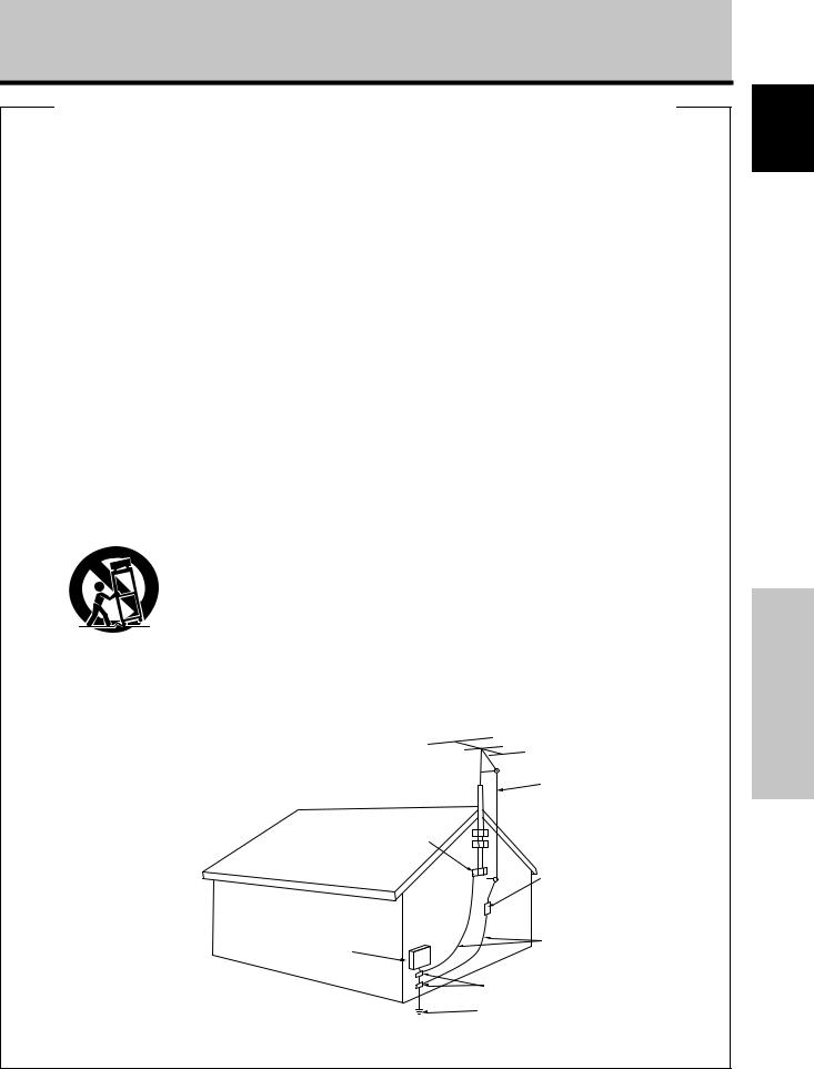
OUTDOOR ANTENNA GROUNDING — If an outside |
÷ If the product has been dropped or damaged in |
product may fall, causing serious injury to a child |
antenna or cable system is connected to the |
any way. |
or adult, and serious damage to the product. Use |
product, be sure the antenna or cable system is |
÷ When the product exhibits a distinct change in |
only with a cart, stand, tripod, bracket, or table |
grounded so as to provide some protection against |
performance — this indicates a need for service. |
recommended by the manufacturer, or sold with |
voltage surges and built-up static charges. Article |
REPLACEMENT PARTS — When replacement parts |
the product. Any mounting of the product should |
810 of the National Electrical Code, ANSI/NFPA |
are required, be sure the service technician has |
follow the manufacturer’s instructions, and should |
70, provides information with regard to proper |
used replacement parts specified by the |
use a mounting accessory recommended by the |
grounding of the mast and supporting structure, |
manufacturer or have the same characteristics as |
manufacturer. |
grounding of the lead-in wire to an antenna |
the original part. Unauthorized substitutions may |
CART — A product and cart combination should be |
discharge unit, size of grounding conductors, |
result in fire, electric shock, or other hazards. |
moved with care. Quick stops, excessive force, |
location of antenna-discharge unit, connection to |
SAFETY CHECK — Upon completion of any service |
and uneven surfaces may cause the product and |
grounding electrodes, and requirements for the |
or repairs to this product, ask the service technician |
cart combination to overturn. |
grounding electrode. See Figure A. |
to perform safety checks to determine that the |
|
LIGHTNING — For added protection for this product |
product is in proper operating condition. |
|
during a lightning storm, or when it is left |
HEAT — The product should be situated away from |
|
unattended and unused for long periods of time, |
heat sources such as radiators, heat registers, |
|
unplug it from the wall outlet and disconnect the |
stoves, or other products (including amplifiers) that |
|
antenna or cable system. This will prevent damage |
produce heat. |
|
to the product due to lightning and power-line |
WALL OR CEILING MOUNTING — The product |
|
surges. |
should be mounted to a wall or ceiling only as |
|
POWER LINES — An outside antenna system should |
recommended by the manufacturer. |
|
not be located in the vicinity of overhead power |
|
|
lines or other electric light or power circuits, or |
|
VENTILATION — Slots and openings in the cabinet |
where it can fall into such power lines or circuits. |
|
are provided for ventilation and to ensure reliable |
When installing an outside antenna system, |
|
operation of the product and to protect it from |
extreme care should be taken to keep from |
|
overheating, and these openings must not be |
touching such power lines or circuits as contact |
|
blocked or covered. The openings should never |
with them might be fatal. |
|
be blocked by placing the product on a bed, sofa, |
OVERLOADING — Do not overload wall outlets, |
|
rug, or other similar surface. This product should |
extension cords, or integral convenience |
|
not be placed in a built-in installation such as a |
receptacles as this can result in a risk of fire or |
|
bookcase or rack unless proper ventilation is |
electric shock. |
|
provided or the manufacturer’s instructions have |
|
|
been adhered to. |
|
|
POWER SOURCES — This product should be operated |
|
|
only from the type of power source indicated on |
|
ANTENNA |
the marking label. If you are not sure of the type |
|
LEAD IN |
of power supply to your home, consult your |
|
|
|
WIRE |
|
product dealer or local power company. |
|
|
LOCATION — The appliance should be installed in a |
|
|
stable location. |
GROUND |
|
NONUSE PERIODS — The power cord of the |
|
|
appliance should be unplugged from the outlet |
CLAMP |
|
when left unused for a long period of time. |
|
|
|
ANTENNA |
|
|
DISCHARGE UNIT |
|
|
(NEC SECTION 810-20) |
|
ELECTRIC |
GROUNDING CONDUCTORS |
|
SERVICE |
||
(NEC SECTION 810-21) |
||
EQUIPMENT |
||
|
||
|
GROUND CLAMPS |
|
Figure A |
POWER SERVICE GROUNDING |
|
|
||
|
ELECTRODE SYSTEM |
|
|
(NEC ART 250, PART H) |
|
|
NEC – NATIONAL ELECTRICAL CODE |
iii
English
Français
Safety Precautions
En

English
Safety Precautions
FEDERAL COMMUNICATIONS COMMISSION
DECLARATION OF CONFORMITY
This device complies with part 15 of the FCC Rules. Operation is subject to the following two conditions: (1) This device may not cause harmful interference, and (2) this device must accept any interference received, including interference that may cause undesired operation.
Product Name: Plasma Display with Video Card
Model Number: PDP-505CMX / PDP-504CMX / PDP-434CMX (Plasma Display)
PDA-5003/PDA-5004 (Video Card)
Product Category: Class B Personal Computers & Peripherals
Responsible Party Name: PIONEER ELECTRONICS (USA) INC. Customer Support Division
Address: P.O. BOX 1760, LONG BEACH, CA., 90801-1760 U.S.A.
Phone: (800)421-1625
URL: http://www.pioneerelectronics.com
Safety Precautions
Should this product require service in the U.S.A. and you wish to locate the nearest Pioneer Authorized Independent Service Company, or if you wish to purchase replacement parts, operating instructions, service manuals, or accessories, please call the number shown below.
8 0 0 – 8 7 2 – 4 1 5 9
Please do not ship your product to Pioneer without first calling the Customer Support Division at the above listed number for assistance.
Pioneer Electronics (USA) Inc.
Customer Support Division
P.O. BOX 1760, Long Beach,
CA 90801-1760, U.S.A.
For warranty information please see the Limited Warranty sheet included with your product.
Should this product require service in Canada, please contact a Pioneer Canadian Authorized Dealer to locate the nearest Pioneer Authorized Service Company in Canada. Alternatively, please contact the Customer Satisfaction Department at the following address:
Pioneer Electronics of Canada, Inc.
Customer Satisfaction Department
300 Allstate Parkway, Markham, Ontario L3R OP2 (905)479-4411 1(877)283-5901
For warranty information please see the Limited Warranty sheet included with your product.
S021_EF
iiiv
En

Contents |
|
Safety Precautions ................................... |
i |
Features ................................................... |
1 |
Before Proceeding ................................... |
3 |
How to use this manual ...................................... |
3 |
Checking supplied accessories .......................... |
5 |
Part Names and Functions ..................... |
6 |
Main unit .............................................................. |
6 |
Remote control unit ............................................ |
7 |
Connection panel ................................................ |
8 |
Installation and Connections ............... |
10 |
Installation of the unit ....................................... |
10 |
Connection to a personal computer ................ |
12 |
Audio connections ............................................ |
13 |
Power cord connection ..................................... |
14 |
How to route cables .......................................... |
15 |
System Settings .................................... |
16 |
Setting the onscreen display language ........... |
16 |
Settings after connections ............................... |
17 |
Operation ............................................... |
19 |
Selecting input source ...................................... |
19 |
Adjusting sound volume .................................. |
20 |
Muting the sound .............................................. |
20 |
Confirming current status ................................ |
20 |
Changing screen size ........................................ |
21 |
Enlarging one part of the screen |
|
(POINT ZOOM) .................................................. |
22 |
Multiscreen display ........................................... |
23 |
Automatic power-off |
|
(POWER MANAGEMENT) ................................ |
24 |
PICTURE/SCREEN Adjustment ............ |
25 |
PICTURE adjustment ........................................ |
25 |
Adjusting screen POSITION, CLOCK, |
|
and PHASE <automatic adjust> ....................... |
26 |
Adjusting screen POSITION, CLOCK, |
|
and PHASE <manual adjust> ........................... |
27 |
Other Operations .................................. |
29 |
Setting the orbiter (ORBITER) .......................... |
29 |
Side mask position (MASK CONTROL) ........... |
29 |
Screen management settings |
|
(SCREEN MGT.) ................................................. |
30 |
Energy saving settings (ENERGY SAVE) ......... |
31 |
Automatic input switching |
|
(AUTO FUNCTION) ........................................... |
32 |
About audio output (AUDIO OUT) |
|
(PDP-504CMX/PDP-434CMX only) ................... |
33 |
Additional Information ......................... |
34 |
Cleaning ............................................................. |
34 |
Troubleshooting ................................................ |
34 |
Precautions regarding use ............................... |
36 |
STANDBY and ON indicators ........................... |
36 |
Specifications .................................................... |
37 |
Appendix 1: Computer signal |
|
compatibility table ............................................ |
38 |
Appendix 2: INPUT1/2 pin assignments ......... |
42 |
Explanation of terms ........................................ |
42 |
Features
PDP-505CMX
¶ Introduces newly developed 50” XGA wide Plasma
Panel technology
The wide high-precision XGA 50” plasma panel (1280x768/16:9) further pushes the envelope of previous high-luminance panels;
producing brighter, clearer images with higher contrast.
¶ Newly developed First Surface Pure Color Filter
The clear front of PDP-505CMX is actually a precisely manufactured, optical-grade, non-glass panel. It acts as a color
filter that increases the spectrum of light emitted by the plasma, for a fuller range of colors and exceptional color accuracy. It also increases contrast by limiting ambient light reflections in bright viewing environments.
¶Newly developed image processing technology (P.U.R.E. Drive) including ACE III (Advanced Continuous Emission) that reproduces images
with higher definition and quality
The newly developed fully digital image processing circuitry (P.U.R.E. Drive) with ACE III (Advanced Continuous Emission) designed exclusively for Pioneer’s high-definition Plasma Displays allows the reproduction of clearer, brighter images.
¶ ES (Expansion Solutions) Card Slot interfaces for
enhanced potential
The display provides a built-in ES Card Slot Interfaces to allow the installation of cards for the connection of external devices, thus enhancing its expansion potential.
¶ Supports wide range of computer signals
(analog and digital)
Supports non-compressed display of signals ranging from 640x400 and 640x480 (VGA) to 1024x768 (XGA) and 1280x768 (WXGA), and compressed display of 1280x768 (SXGA) and 1600x1200 (UXGA) signals.
* Supported signals are different on INPUT1 and INPUT2.
¶Free Installation Configuration
– Broader installation possibilities with thinner,
lighter, high-endurance design –
The display is only 98mm thick with lightweight. On the other hand, the efficient heat-radiating design greatly improves environmental operating conditions. The thinner, lighter design, coupled to high-endurance construction greatly broadens the range of possible installation locations and styles.
¶ High reliability for commercial applications
This display is provided with features giving it high dependability in commercial applications, including the ability to suppress peak luminance in accordance with the viewing program, and to change the cooling fan’s speed in accordance with changes in operating environment.
¶ Power-Saving Design
While equipped with a high-precision (1280x768) panel, this unit achieves the highest energy-saving of any display in its class (50inch XGA class: 360W). The display is also provided with a variety of power-saving functions, including an automatic brightness function with ambient light sensor.
English
Features
1
En

English
Features
Features
The high-precision Plasma Display PDP-505CMX incorporates the latest in color filter technology – 1st Surface Pure Color Filter. This improves the color / picture reproduction of these models as compared to previous models. It also eliminates the need for a physical glass panel to be placed in front of the plasma panel, which furthers Pioneer’s continued goal of reducing environmental waste in consumer electronics, now during the manufacturing process and in the future during the recycling process.
Note
The following are typical effects and characteristics of a phosphor-based matrix display and as such, are not covered by the manufacturer’s limited warranties:
•Permanent residual images upon the phosphors of the panel.
•The existence of a minute number of inactive light cells.
PDP-504CMX/PDP-434CMX
¶Image processing technology (P.U.R.E. Drive) including ACE (Advanced Continuous Emission) II reproduces images with higher definition and
quality
The newly developed fully digital image processing circuitry (P.U.R.E. Drive) including ACE (Advanced Continuous Emission) II designed exclusively for Pioneer’s high-definition Plasma Displays allows the reproduction of clearer, bright images.
¶ ES (Expansion Solutions) Card Slot interfaces for enhanced potential
The display is provided with a built-in ES Card Slot Interfaces to allow the installation of cards for the connection of external devices, thus enhancing its expansion potential.
¶Supports wide range of computer signals (analog/ digital)
¶Optional line (sold separately)
(For details, please consult the dealer where this unit was purchased.)
1 Table top stand: PDP-505CMX/PDP-504CMX/PDP-434CMX display stand.
2 Wall installation unit:
Wall installation bracket designed as a wall interface for securing the unit.
3Speaker system designed specifically for Plasma Displays (width: 7.4 cm (2-29/32 in.)): 2-way speaker units featuring 2.5
cm (31/32 in.) dome conical tweeter and newly developed 14.6 cm (5-3/4 in.) x 6.2 cm (2-7/16 in.) eliptical speaker in vertical arrangement. (When speakers are attached, the operation panel on this unit is not operable.)
4 Video card: |
Expansion card allows viewing of video signals |
|
and computer analog RGB signals. |
|
Cards used in the expansion slots should be |
|
manufactured or recommended by Pioneer. |
|
Using other expansion cards may result in |
|
malfunction. |
This product includes FontAvenue® fonts licensed by NEC Corporation.
FontAvenue is a registered trademark of NEC Corporation.
Supports non-compressed display of signals ranging from 640x400 and 640x480 (VGA) to 1024x768 (XGA) and 1280x768 (WXGA), and compressed display of 1280x768 (SXGA) and 1600x1200 (UXGA) signals.
* Supported signals are different on INPUT1 and INPUT2.
¶Free Installation Configuration
– Broader installation possibilities with thinner,
lighter, high-endurance design –
The thinner, lighter design, coupled to high-endurance construction greatly broadens the range of possible installation locations and styles.
¶ High reliability for commercial applications
This display is provided with features giving it high dependability in commercial applications, including the ability to suppress peak luminance in accordance with the viewing program, and to change the cooling fan’s speed in accordance with changes in operating environment.
¶ Power-Saving Design
While equipped with a high-precision (50-inch: 1280x768, 43inch: 1024x768) panel, this unit achieves the highest energysaving of any display in its class (50-inch XGA class: 360W, 43inch XGA class: 298W). The display is also provided with a variety of power-saving functions, including an automatic brightness function with ambient light sensor.
2
En
Before Proceeding
How to use this manual
This manual is set up to follow the course of actions and operations in the order that would seem most logical for someone setting up this unit.
Once the unit has been taken out of the box and it has been confirmed that all the parts have been received (page 5), it may be beneficial to look over the section “Part Names and Functions” starting on page 6 to become acquainted with the plasma monitor and remote control unit, as their respective buttons and controls will be referred to throughout this manual.
The section “Installation and Connections” starting on page 10 covers all the necessary points regarding installation of the Plasma Display and connections to a wide variety of components.
The section “System Settings” starting on page 16 covers the on-screen settings necessary for correct operation of the Plasma Display with its connected components. Depending on the connections made, this section may or may not be necessary.
The remainder of the sections in this manual is dedicated to the basic operations associated with selecting a source component up to the more complex operations associated with adjusting the Plasma Display picture to match the requirements of specific components and personal preferences.
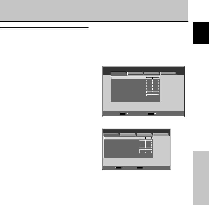
Regarding menu displays
The example menu displays provided in this manual are those for the PDP-505CMX/PDP-504CMX model. The PDP-434CMX display differs as shown:
Example of PDP-505CMX/PDP-504CMX Menu
Display:
MENU |
|
|
|
INPUT1 |
PICTURE |
SCREEN |
SETUP |
OPTION |
|
CONTRAST |
|
: |
0 |
|
BRIGHTNESS |
: |
0 |
|
|
R.LEVEL |
|
: |
0 |
|
G.LEVEL |
|
: |
0 |
|
B.LEVEL |
|
: |
0 |
|
H.ENHANCE |
: |
0 |
|
|
V.ENHANCE |
|
: |
0 |
|
PICTURE RESET |
|
|
|
|
SET |
ENTER |
|
MENU |
EXIT |
Example of PDP-434CMX Menu Display:
MENU |
|
|
|
INPUT1 |
PICTURE |
SCREEN |
SETUP |
OPTION |
|
CONTRAST |
: |
0 |
|
|
BRIGHTNESS |
: |
0 |
|
|
R.LEVEL |
: |
0 |
|
|
G.LEVEL |
: |
0 |
|
|
B.LEVEL |
: |
0 |
|
|
H.ENHANCE |
: |
0 |
|
|
V.ENHANCE |
: |
0 |
|
|
PICTURE RESET |
|
|
|
|
SET |
ENTER |
MENU |
EXIT |
|
Please note that the actual contents displayed are the same for both the PDP-505CMX/PDP-504CMX and PDP434CMX.
English
Before Proceeding
3
En
English
Before Proceeding
About operations in this manual
Each operation is described in its proper operating order. These Operating Instructions will refer to the operating controls found on the remote control unit, with the exception of those buttons found only on the main Plasma Display itself. When the Plasma Display controls include equivalent buttons to those found on the remote control unit, the commands can be performed on the main unit as well.
The following illustrations are an example of the actual operations used for the section “PICTURE adjustment”. The examples are provided to allow you to confirm whether the operation is performed correctly or not.
Note
The screen images depicted in these Operating Instructions should be considered typical images; some difference will be seen in practice, depending on the screen item displayed and its contents, the input source and various other control settings.
Before Proceeding
4
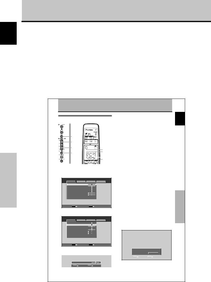
PICTURE/SCREEN Adjustment
PICTURE adjustment
MENU
5/∞
2/3
MENU
2/3
SET
 SET
SET
5/∞
Main unit operating |
Remote control unit |
panel |
|
1 Press the MENU button to display the menu
screen. |
|
|
|
|
MENU |
|
|
|
INPUT1 |
PICTURE |
SCREEN |
SETUP |
OPTION |
|
CONTRAST |
|
: |
0 |
|
BRIGHTNESS |
: |
0 |
|
|
R.LEVEL |
|
: |
0 |
|
G.LEVEL |
|
: |
0 |
|
B.LEVEL |
|
: |
0 |
|
H.ENHANCE |
: |
0 |
|
|
V.ENHANCE |
|
: |
0 |
|
PICTURE RESET |
|
|
|
|
SET |
ENTER |
|
MENU |
EXIT |
2Use the 5/∞ buttons to select the adjustment item, then press the SET button.
MENU |
|
|
|
INPUT1 |
PICTURE |
SCREEN |
SETUP |
OPTION |
|
CONTRAST |
|
: |
0 |
|
BRIGHTNESS |
: |
0 |
|
|
R.LEVEL |
|
: |
0 |
|
G.LEVEL |
|
: |
0 |
|
B.LEVEL |
|
: |
0 |
|
H.ENHANCE |
: |
0 |
|
|
V.ENHANCE |
|
: |
0 |
|
PICTURE RESET |
|
|
|
|
SET |
ENTER |
|
MENU |
EXIT |
3Use the 2/3 buttons to adjust the picture quality as desired.
|
BRIGHTNESS |
: 0 |
|
|
||
|
|
|
||||
|
|
|
SET |
|
EXIT |
|
|
|
|
|
|
|
|
4Press the SET button.
Pressing the SET button writes the value into the memory and returns the display to the step 2 screen.
5When the setup is finished, press the MENU button to exit the menu screen.
Note
Make these adjustments for each input (INPUT1 or INPUT2) and signals.
[PICTURE] mode adjustment items
Below are brief descriptions of the options that can be set in the [PICTURE] mode.
CONTRAST ············· Adjust according to the surrounding brightness so that the picture can be seen clearly.
BRIGHTNESS ·········· Adjust so that the dark parts of the picture can be seen clearly.
R. LEVEL ················· Adjust the amount of red in the picture.
G. LEVEL ················· Adjust the amount of green in the picture.
B. LEVEL ················· Adjust the amount of blue in the picture.
H. ENHANCE ··········· Sharpens the image in the horizontal direction.
V. ENHANCE ··········· Sharpens the image in the vertical direction.
To reset [PICTURE] mode settings to the default
If settings have been adjusted excessively or the picture on the screen no longer appears natural, it may prove more beneficial to reset the [PICTURE] mode to default settings instead of trying to make adjustments under already adjusted conditions.
1In step 2 in the previous procedure, use the 5/∞ buttons to select [PICTURE RESET], then press the SET button.
PICTURE RESET
|
|
|
YES |
|
|
NO |
|
|
|
|
|
|
|
|
|
|
|
|
|
|
|
|
|
|
SET |
SET |
MENU |
EXIT |
|||
2Use the 2/3 buttons to select [YES], and press the SET button.
All [PICTURE] mode settings are returned to the factory set default.
25
En
English
PICTURE/SCREEN Adjustment
En
Before Proceeding
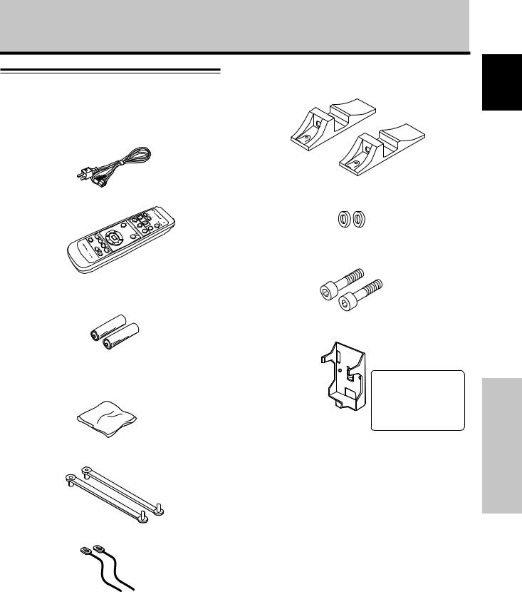
Checking supplied accessories
Check that the following accessories were supplied.
1 Power cord
2 Remote control unit
3 AA (R6) batteries (x 2)
4 Cleaning cloth (for screen)
5 Speed clamps (x 2)
7 Display stands (x 2)
8 Washers (x 2)
9 Hex hole bolts (x 2)
0 Remote control unit holder
Use as a holder for the remote control unit. When attaching to the rear of the main unit, be careful not to cover the vents.
÷These Operating Instructions
÷Warranty
6 Bead bands (x 2)
English
Before Proceeding
5
En
English
Part Names and Functions
Part Names and Functions
Main unit |
Operation panel on the main unit |
|
|
PDP-434CMX |
Main unit |
6 |
6 |
PDP-505CMX/
PDP-504CMX
7
8
9

 0 -
0 -
=
~
!
|
1 |
2 |
Note |
|
|
|
When optional speakers have been connected, |
3 |
4 5 |
|
the operation panel on the main unit is blocked |
|
and unavailable. |
||
|
|
|
Main unit
1 Display stand
2Remote control sensor
Point the remote control toward the remote sensor to operate the unit (page 8).
3Ambient light sensor
This sensor measures the level of light inside the viewing room; it is enabled when the [ENERGY SAVE] option is set to [AUTO] (page 31).
4ON indicator
The indicator lights green when the Plasma Display is powered up and functional (page 19).
When flashing, the indicator signals that there are error messages (page 36).
The indicator flashes green once per second when the [POWER MANAGEMENT] function is operational
(page 24).
5STANDBY indicator
The indicator lights red when the unit is in standby mode (page 19) but flashes to signal that there are errors (page 36).
6Handles
The handles are attached in different ways on the Plasma Displays PDP-505CMX/PDP-504CMX and PDP-434CMX, but the handles themselves are used in the same way on these models (page 11).
6
Operation panel on the main unit
7STANDBY/ON button
Press to put the display in operation or standby mode (page 19).
8INPUT button
Press to select the input (page 19).
9MENU button
Press to open and close the on-screen menu (pages 16 to 33).
0ADJUST ( /
/ /
/ /
/ ) buttons
Use these buttons to move the onscreen cursor between selection options and to perform any adjustments. Instructions for use are given with each on-screen command option (pages 16 to 33).
-VOLUME (+/–) buttons
When not being used with on-screen menu items, these buttons adjust the volume of the sound (pages 19 and 20).
=SET/DISPLAY button
Use to confirm on-screen menu selections and to change settings (pages 16 to 33).
When not being used by on-screen menus, the option can display the current set status (page 20).
~SCREEN SIZE button
Press to select the screen size (page 21).
!AUTO SET UP button
When using computer signal input, this automatically sets the [POSITION], [CLOCK] and [PHASE] to the optimum values (page 26).
En
Part Names and Functions
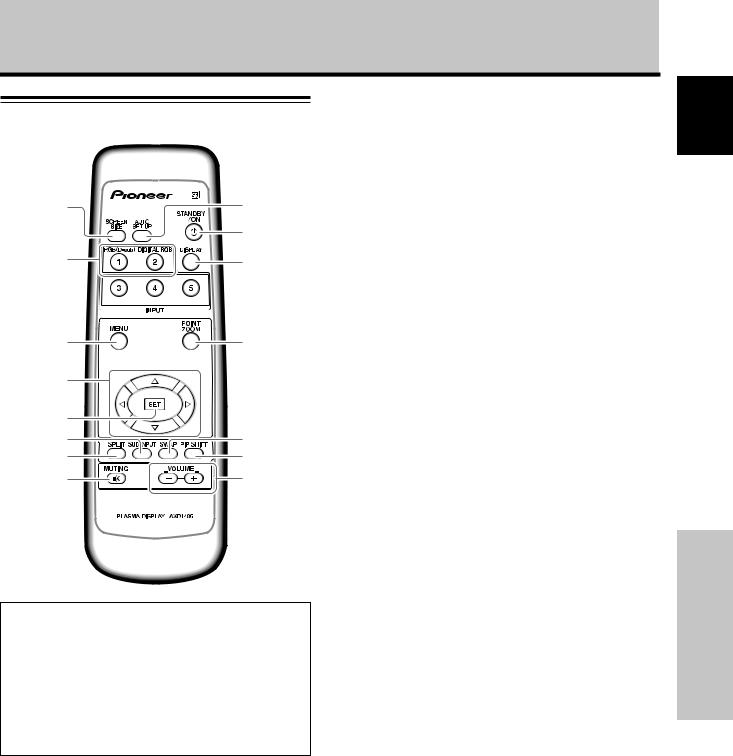
Remote control unit
1 9
0
2 -
3 |
= |
4 |
|
5 |
|
6 |
~ |
7 |
! |
8 |
@ |
When handling the remote control unit
¶Do not drop or throw the remote control unit as this can result in disconnect wires or a cracked casing.
¶Do not use the remote control unit where it is subject to direct sunlight, heat radiation from a heater, or in a place subject to excessive humidity or moisture.
¶When the remote control unit’s batteries begin to wear out, the operable distance will gradually become shorter. When this occurs, replace all batteries with new ones as soon as possible.
1SCREEN SIZE button
Press to select the screen size (page 21).
2INPUT buttons
Press to select the input (page 19).
3MENU button
Press to reveal and hide the on-screen menu (pages 16 to 33).
4ADJUST (5/∞/3/2) buttons
Use to navigate menu screens and to adjust various settings on the unit (pages 16 to 33).
5SET button
Press to adjust or enter various settings on the unit (pages 16 to 33).
6SUB INPUT button
During multi-screen display, use this button to change inputs to subscreens (page 23).
7SPLIT button
Press to switch to multi-screen display (page 23).
8MUTING button
Press to mute the volume (page 20).
9AUTO SET UP button
When using computer signal input, automatically sets the [POSITION], [CLOCK] and [PHASE] to optimum values (page 26).
0STANDBY/ON button
Press to put the unit in operation or standby mode (page 19).
-DISPLAY button
Press to view the unit’s current input and setup mode (page 20).
=POINT ZOOM button
Use to select and enlarge one part of the screen (page 22).
~ SWAP button
During multi-screen display, use this button to switch between main screen and subscreen (page 23).
!PIP SHIFT button
When using PinP mode with multi-screen display, use this button to move the position of subscreen (page 23).
@VOLUME (+/–) buttons
Use to adjust the volume (pages 19 and 20).
English
Part Names and Functions
7
En
English
Part Names and Functions
Part Names and Functions
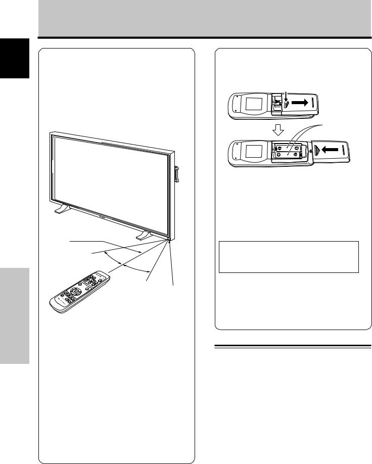
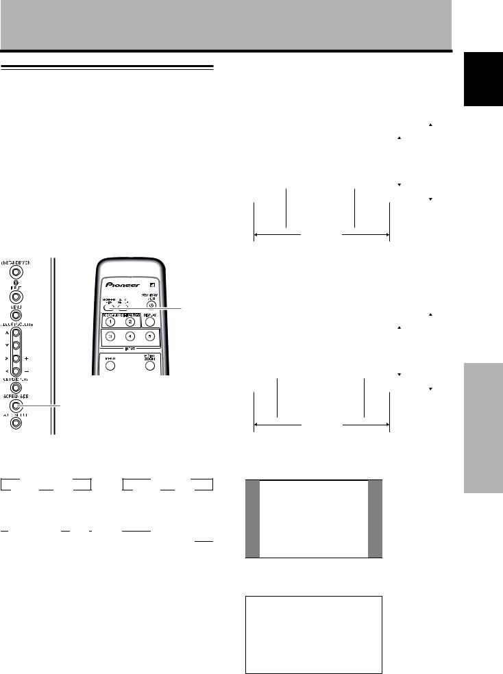
Operating range of the remote control unit
When operating the remote control unit, point it at the remote sensor (Î) located on the front panel of the main unit. The remote control unit is operable up to 7 m from the unit and within a 30 angle on each side of the sensor.
7 m
(23 feet)
30°
30°
Remote Sensor
If you are having difficulty with operation of the remote control unit
¶The remote control unit may not operate if there are objects placed between it and the display.
¶Operational distance will gradually become shorter as the batteries begin to wear out, replace weak batteries with new ones as soon as possible.
¶This unit discharges infrared rays from the screen. Placing a video deck or other component that is operated by an infrared remote control unit near this unit may hamper that component’s reception of the remote control’s signal, or prevent it from receiving the signal entirely. Should this occur, move the component to a position further away from this unit.
¶Depending on the installation surroundings, this unit’s remote control unit may be influenced by the infrared rays discharged from the Plasma Display, hampering reception of its rays or limiting its operational distance. The strength of infrared rays discharged from the screen will differ according to the picture displayed.
8
Inserting the batteries in the remote control unit
While pressing down lightly, slide in the direction of the arrow.
Two AA (R6) batteries
 CAUTION
¶Insert batteries so that the plus (+) and minus (–) sides are aligned according to the markings in the battery case.
¶When not using the remote control unit for a long period of time (1 month or more), remove the batteries from the remote control unit to prevent leaking of battery fluid. If battery liquid has leaked, thoroughly wipe the inside of the case until all liquid is removed before inserting new batteries.
When disposing of used batteries, please comply with governmental regulations or environmental public instruction’s rules that apply in your country/area.
 NO!
NO!
¶Do not mix new batteries with used ones.
¶The voltage of batteries may differ even if they are the same shape. Please do not mix different kinds of batteries together.
¶Do not charge, short, disassemble or throw the provided batteries in a fire.
Connection panel (next page)
The connection panel provides two video input terminals and one video output terminal. Audio input/output and speaker output terminals are also provided. For information or instructions regarding connections, consult the pages noted in parentheses by each item.
1SPEAKER (R) terminal
For connection of an external right speaker. Connect a speaker that has an impedance of 8 -16 Ω
(page 13).
2COMBINATION IN/OUT
Never connect any component to these connectors without first consulting your Pioneer installation technician.
These connectors are used for Plasma Display setup adjustments.
En
Part Names and Functions
Illustration depicts PDP-505CMX/PDP-504CMX model.
English
POWER |
AC IN |
OFF ON
SPEAKER |
L |
|
+ |
– |
|
8Ω ~16Ω |
|
|
0 


 -
- 


 =
=
R |
SPEAKER |
IN |
OUT |
ANALOG RGB IN |
ANALOG RGB OUT INPUT1 |
|
INPUT2 |
OUTPUT |
||
D-Sub |
D-Sub |
AUDIO |
DIGITAL RGB |
AUDIO |
AUDIO |
|||||
8Ω ~16Ω |
|
|
|
|
||||||
+ |
– |
|
|
|
|
|
DVI-D |
|
|
|
|
COMBINATION |
RS-232C |
|
|
|
|
|
1 |
2 |
3 |
4 |
5 |
6 |
7 |
89 |
3RS-232C
Never connect any component to this connector without first consulting your Pioneer installation
technician.
This connector is used for Plasma Display setup adjustments.
4ANALOG RGB IN (INPUT1) (mini D-sub 15 pin)
For connection of a personal computer (PC) or similar component. Verifiy that the connection corresponds to the format of the signal output from the added component (page 12).
5ANALOG RGB OUT (INPUT1) (mini D-sub 15 pin)
Use the ANALOG RGB OUT (INPUT1) terminal to output the video signal to an external monitor or other component.
Note: The video signal is not output from the ANALOG RGB OUT (INPUT1) terminal when the unit is powered OFF or placed in Standby mode.
(page 12)
8AUDIO (INPUT2) (Stereo mini jack)
Use to obtain sound when INPUT2 is selected. Connect a component's audio output jack to the panel's INPUT2 (page 13).
9AUDIO (OUTPUT) (Stereo mini jack)
Use to output a selected source component's audio connected to this unit to an AV amplifier or a similar device.
Note: No sound is produced from the AUDIO (OUTPUT) jack when the power is switched OFF or set to ON (Standby)
(page 13).
0MAIN POWER switch
Use to switch the main power of the unit ON and OFF.
-AC IN
Use to connect the supplied power cord to an AC outlet (page 14).
=SPEAKER (L) terminal
For connection of an external left speaker. Connect a speaker that has an impedance of 8 -16 Ω (page 13).
6AUDIO (INPUT1) (Stereo mini jack)
Use to obtain sound when INPUT1 is selected. Connect a component's audio output jack to the panel's INPUT1 (page 13).
7DIGITAL RGB (INPUT2) (DVI-D jack)
Use to connect a computer.
Note: This unit does not support displaying of copyguard-protected video signals (page 12).
9
Part Names and Functions
En
English
Installation and Connections
Installation and Connections
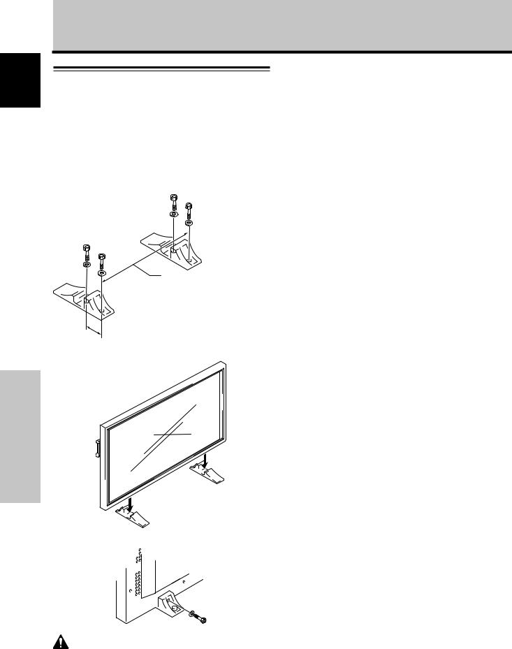
Installation of the unit
Installation using the supplied display stands
Be sure to fix the supplied stands to the installation surface. Use commercially available M8 bolts that are 25 mm
(1 in.) longer than the thickness of the installation surface.
1Fix the supplied stands to the installation surface at each of the 4 prepared holes using commercially available M8 bolts.
Front
|
PDP-505CMX: |
|
798 mm (31-7/16 in.) |
|
(Bolt hole thread pitch) |
Rear |
PDP-434CMX: 880 mm (34-11/16 in.) |
|
(Bolt hole thread pitch) |
Always install the supplied display stands according to the dimensions
shown in the accompanying illustration.
110 mm (4-5/16 in.)
2 Set the panel in the stands.
3 Attach unit using supplied washer and bolts.
Use a 6 mm (1/4 in.) hex wrench to bolt them.
Installation using the optional PIONEER stand or installation bracket
÷Please employee professional assistance when mounting or installing the panel. Your Pioneer representative or the dealer who sold the display can help you find an installation specialist.
÷When installing, be sure to use the bolts provided with the stand or installation bracket.
÷For installation procedure details, please refer to the instruction manual provided with the stand or installation bracket.
Installation using accessories other than the PIONEER stand or installation bracket (sold separately)
÷When possible, please install using parts and accessories manufactured by PIONEER. PIONEER is not responsible for accident or damage caused by the use of parts and accessories manufactured by other companies.
÷For custom installations, please consult a qualified installer or with the dealer where the unit was purchased.
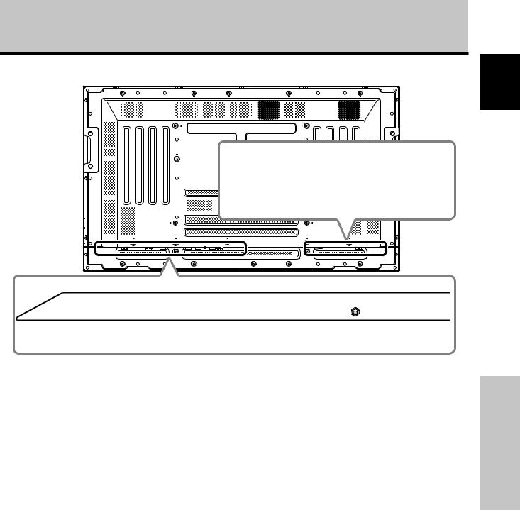
Wall-mount installation of the unit
This unit is designed with bolt holes for wallmount installation, etc. The installation holes are shown in the accompanying illustration.
÷Attach in 4 or more locations above, below, left, and right of the center line.
÷Use bolts that are long enough to be inserted 12 mm (1/2 in.) to 18 mm (11/16 in.) into the main unit from the attaching surface; for both A holes and B holes. Refer to the sideview diagram in the accompanying illustration.
÷This unit is constructed with glass; be sure to install
it on a flat, unwarped surface.
 CAUTION
To avoid malfunctions, overheating of this unit, and possible fire hazard, verify that the unit's vents are not blocked after being installed. Also, as hot air is expelled from the air vents, check for deterioration or dirt build up on the wall or other objects behind the panel.
 CAUTION
Please use only an M8 (Pitch = 1.25 mm) bolt. (Only this size bolt provides the necessary strength for proper installation.)
 CAUTION
This display unit weighs 67 pounds (30 kg) and has little front- to-back depth, making it very unstable when stood on edge. As a precaution, two or more should work as a team when unpacking, moving, or installing the plasma display.
 CAUTION
This unit incorporates a thin design. To ensure safety if installed in a location subject to vibrations or shaking, take measures to prevent the unit from tipping over.
10
En

Installation and Connections
 CAUTION
÷Handles should not be removed or reattached by anyone other than the professional installation technician or service personnel.
÷If handles must be removed due to specific installation conditions, the mounting screws should be stored carefully together with the handles. To ensure safety, the mounting screws should be tightened to a minimum torque of 2N·m (20 kgf·cm) when reattaching the handles.
÷When moving the display, it should always be carried by two people holding the rear handles as shown below.
 NO!
NO!
÷Never attempt to move the Plasma Display by holding only one of the handles.
÷When installing the Plasma Display, do not use the handles as means of hanging the display; also do not use them as devices to prevent tipping over (see illustration).
English
Français
|
Air vents (fan) |
b hole |
b hole |
|
|
|
|
|
Attaching surface |
|
|
|
|
|
|
Installation |
|
|
|
|
|
|
bracket, etc.. |
|
|
|
|
|
Main unit |
a hole |
|
|
|
|
|
|
|
|
|
|
|
|
Center line |
Bolt |
Connections |
b hole |
a hole |
|
a hole |
b hole |
||
|
|
|||||
|
|
|
|
|
12 mm to 18 mm |
|
|
|
|
|
|
and |
|
|
|
|
|
|
(1/2 in. to 11/16 in.) |
|
|
|
|
|
|
Bolt |
Installation |
|
|
|
|
b hole |
||
|
b hole |
Center line |
b hole |
12 mm to 18 mm (1/2 in. to 11/16 in.) |
||
Rear view diagram (PDP-505CMX/PDP-504CMX) |
Side view diagram |
Air vents (fan)
|
|
|
Center line |
b hole |
a hole |
|
a hole |
|
|
|
b hole |
|
b hole |
Center line |
b hole |
|
|
Rear view diagram (PDP-434CMX)
11
En

English
Installation and Connections
Installation and Connections
When connecting to ANALOG RGB OUT (INPUT1)
Connection to a personal computer
Connection method differs depending on the computer type. When connecting, please refer to the computer's instruction manual.
Before connecting, verify that the computer's power and the panel's power are OFF.
Connection to INPUT1
Connect the display’s D-sub input connector to the computer's D-sub output (analog RGB). This connector also supports G ON SYNC (output with green signal combined with sync signal), and composite SYNC (output with combined horizontal and vertical sync signals).
When connecting to ANALOG RGB IN (INPUT1)
|
ANALOG RGB IN |
ANALOG RGB OUT |
INPUT1 |
|
||||
|
D-Sub |
D-Sub |
AUDIO |
|
||||
|
|
|
|
|
|
|
|
|
|
|
|
|
|
|
|
|
|
|
|
|
|
|
|
|
|
|
|
|
|
|
|
|
|
|
|
|
|
|
|
|
|
|
|
|
Connect the cable corresponding to the shape of the panel's input terminal and to the computer’s output terminal. Secure by tightening the terminal screws on both units.
To complete the installation, follow the on-screen setup. See pages 16 to 18 for details.
Note:
Depending on the computer model being connected, a conversion device or adapter (provided with the computer or sold separately) may be necessary. For details, please refer to the computer's instruction manual or consult
the computer maker or your nearest dealer.
NOTICE
¶INPUT1 supports Microsoft “Plug & Play” (VESA DDC 1/2B) components. See Appendix 2-1/2 (page 42) when using INPUT1.
¶See Appendix 1 (pages 38 and 40) for information regarding signals and display formats supported by INPUT1.
|
ANALOG RGB IN |
ANALOG RGB OUT |
INPUT1 |
||
|
D-Sub |
D-Sub |
AUDIO |
||
|
|
|
|
|
|
|
|
|
|
|
|
|
|
|
|
|
|
|
|
|
|
|
|
|
|
|
|
|
|
To an external monitor
With this unit, it is possible to output the video signal to an external monitor or other component through the ANALOG RGB OUT (INPUT1) terminal.
Note:
A video signal is not output from the ANALOG RGB OUT (INPUT1) terminal when the panel's power is OFF or in Standby mode.
Connection to INPUT2
A computer equipped with DVI output (digital RGB signal) can be connected to the video card’s DVI connector.
|
|
|
|
|
|
INPUT2 |
|
|
|
|
DIGITAL RGB |
AUDIO |
|
|
|
||||
|
DVI-D |
|
|
|
|
||||
|
|
|
|
|
|
|
|
|
|
|
|
|
|
|
|
|
|
|
|
|
|
|
|
|
|
|
|
|
|
|
|
|
|
|
|
|
|
|
|
|
|
|
|
|
|
|
|
|
|
|
|
|
|
|
|
|
|
|
|
|
|
|
|
|
|
|
|
|
|
To complete the installation, follow the on-screen setup See pages 16 to 18 for details.
Reminders
¶Use a DVI-D 24-pin (digital only) cable for the connection.
¶This unit does not support displaying copyguard-protected video signals.
NOTICE
¶INPUT2 supports Microsoft “Plug & Play” (VESA DDC 2B) components. See Appendix 2-2/2 (page 42) when using
INPUT2.
¶See Appendix 1 (pages 39 and 41) for information regarding signals and display formats supported by INPUT2.
12
En
Installation and Connections
Audio connections for component (computer)
Audio connections
Before connecting, verify that the audio device's power and panel's power are OFF.
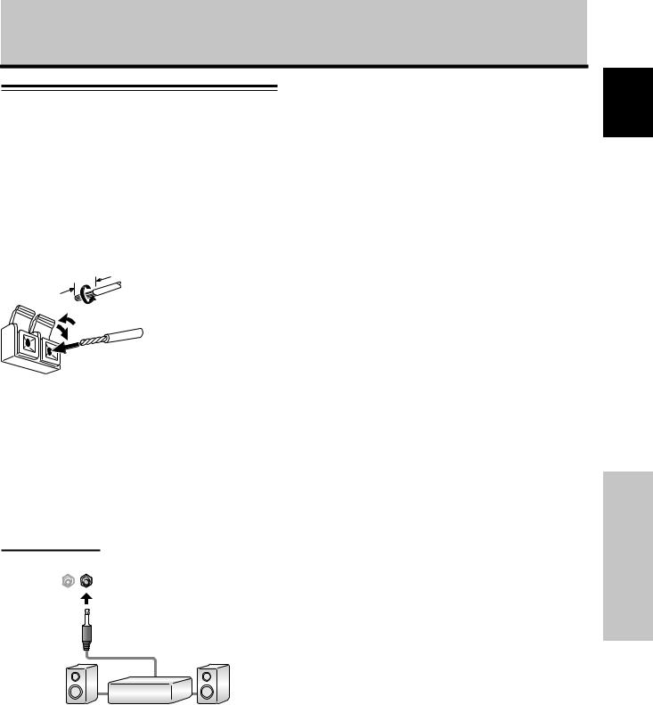
Connecting the speakers
This unit is equipped with speaker output terminals for connection to a speaker system (sold separately) especially designed for use with this unit. Refer to the illustrations below when connecting the speaker system.
12 |
mm |
Twist exposed |
|
wire strands |
|
|
|
|
|
|
together. |
Push tab to the open position, and insert the wire. Then, close tab firmly to secure the wire in place.
Reminders
÷After connecting the wires, pull gently on the cables to confirm that the wire cores are fastened securely in their terminals.
Loose connections can result in noise or interrupted sound.
÷Do not allow the wire cores of the ª and · speaker cables to protrude excessively. If the wires touch each other, they can cause a short circuit. Shorts can produce excessive load on the panel, causing a malfunction or stopping all operations.
Connection to audio output connector
Use a stereo miniplug to connect the panel’s AUDIO (OUTPUT) stereo mini jack (L/R) to an AV amplifier or other audio device.
|
DIGITAL RGB |
INPUT2 |
OUTPUT |
|
||||
|
AUDIO |
AUDIO |
||||||
|
DVI-D |
|
|
|
|
|
||
|
|
|
|
|
|
|
|
|
|
|
|
|
|
|
|
|
|
|
|
|
|
|
|
|
|
|
|
|
|
|
|
|
|
|
|
|
|
|
|
|
|
|
|
|
connected to INPUT1
ANALOG RGB OUT INPUT1
D-Sub |
AUDIO |
A stereo miniplug cable can be used to connect a device's audio output from INPUT1 to the panel's AUDIO (INPUT1) stereo mini jack (L/R).
Sound is output from both the AUDIO (OUTPUT) stereo mini jack (L/R) and the SPEAKER (L/R) terminals, as set through the video input selection.
Audio connections for component (computer) connected to INPUT2
|
DIGITAL RGB |
INPUT2 |
|
|
|||||
|
AUDIO |
|
|
|
|||||
|
DVI-D |
|
|
|
|
|
|
||
|
|
|
|
|
|
|
|
|
|
|
|
|
|
|
|
|
|
|
|
|
|
|
|
|
|
|
|
|
|
|
|
|
|
|
|
|
|
|
|
|
|
|
|
|
|
|
|
|
|
|
|
|
|
|
|
|
|
|
|
|
|
|
|
|
|
|
|
|
|
Making connections to the audio inputs on this unit
This unit features two audio inputs and one audio output. The following chart shows the video inputs and the corresponding audio input terminals.
Video |
Audio input jacks |
Sound output |
|
input |
|||
|
|
||
|
|
|
|
INPUT1 |
Stereo mini jack |
Sound of the selected video |
|
(L/R) |
input is output from the |
||
|
|||
INPUT2 |
Stereo mini jack |
• SPEAKER (L/R) terminals |
|
(L/R) |
• Stereo mini jack (L/R) |
||
|
|||
|
|
|
A stereo miniplug cable can be used to connect a device's audio output from INPUT2, to the panel's AUDIO (INPUT2) stereo mini jack (L/R).
Sound is output from both the AUDIO (OUTPUT) stereo mini jack (L/R) and the SPEAKER (L/R) terminals, as set through the video input selection.
13
English
Français
Installation and Connections
En
English
Installation and Connections
Installation and Connections
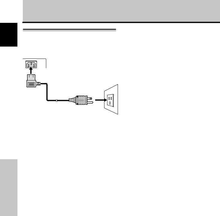
Power cord connection
Connect the power cord last, after all other connections have been completed.
1Connect the power cord to the plasma display panel.
2Plug the power cord into an outlet.
 CAUTION
÷Use only the power cord provided.
÷For the Plasma Display, a three-core power cord with a ground
terminal is used for efficiency protection.
Always connect the power cord to a three-pronged, grounded outlet, making sure that the cord is properly grounded. If you use a power source converter plug, use an outlet with a ground terminal and screw down the ground line.
 NO!
NO!
Do not use a power supply voltage other than that indicated (AC 100 - 120 V, 50/60 Hz) as this may cause fire or electric shock.
14
En
Installation and Connections
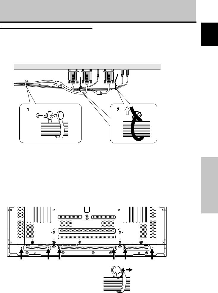
How to route cables
Speed clamps and bead bands for bunching cables together are shipped with this panel. Once components are connected, route and bundle cables according to the following instructions.
* As viewed from the rear of the display.
1 2
English
Français
1Organize cables together using the provided speed clamps.
Insert 1 into an appropriate hole on the rear of the unit then snap 2 into the back of 1 to fix the clamp.
Speed clamps are designed to be difficult to undo once in place. Please attach carefully.
To attach the speed clamps to the main unit
Connect the speed clamps using the 6 holes marked with “‡” below, depending on the situation.
2Bunch separated cables together and secure them
with the provided bead bands.
Do not allow excessive stress to be placed on the cable ends.
Note
Cables can be routed to the left or to the right.
Illustration depicts PDP-505CMX/ PDP-504CMX model.
* As viewed from the rear of the display.
To remove speed clamps
Using pliers, twist the clamp 90° and pull it outward. In some cases the clamp may have deteriorated over time and may get damaged when removed.
15
Installation and Connections
En
English
System Settings
System Settings
Setting the onscreen display language
The onscreen display language has been set to English as the factory default. To change to another language, the screen setting must be changed. Follow the procedures below to change the language.
STANDBY/
ON
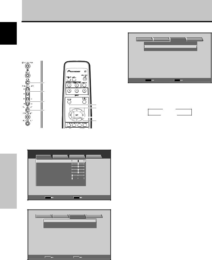
4 Use the 2/3 buttons to select [OPTION].
MENU |
|
|
INPUT1 |
PICTURE |
SCREEN |
SETUP |
OPTION |
LANGUAGE |
|
: ENGLISH |
|
ENERGY SAVE |
|
: STANDARD |
|
SCREEN MGT. |
|
: OFF |
|
ORBITER |
|
: OFF |
|
MASK CONTROL |
|
: ON |
|
AUTO SET UP MODE |
: INACTIVE |
||
AUTO FUNCTION |
|
: OFF |
|
AUDIO OUT |
|
: FIXED |
|
SET |
ENTER |
MENU |
EXIT |
|
STANDBY/ |
MENU |
ON |
5/∞ |
|
2/3 |
|
|
MENU |
SET |
2/3 |
|
|
|
SET |
|
5/∞ |
Main unit operating |
Remote control unit |
panel |
|
5Use the 5/∞ buttons to select [LANGUAGE] then press the SET button.
LANGUAGE |
: |
ENGLISH |
SET SET |
|
MENU EXIT |
1 |
Set the rear panel MAIN POWER switch to ON. |
6 Use the 2/3 buttons to select the desired language. |
||||||||
|
Each time an 2/3 button is pressed, the option |
|||||||||
|
The STANDBY indicator on the front panel lights red. |
|
||||||||
|
|
cycles through the available languages, in the order |
||||||||
|
|
|
||||||||
2 |
Press the STANDBY/ON button to turn power ON. |
|
shown below: |
|
|
|
|
|
||
|
|
|
3 ENGLISH 2 |
3 FRANÇAIS 2 |
3 |
ESPAÑOL 2 |
|
|||
|
The ON indicator on the front panel lights green. |
|
|
|
|
|||||
|
|
|
|
|
||||||
3 |
|
|
3 |
2 3 |
|
2 3 ITALIANO 2 3 DEUTSCH 2 |
|
|||
Press the MENU button to display the menu |
|
|
|
|
||||||
|
|
|
|
|||||||
|
|
|
|
|
|
|
|
|
||
screen. |
|
|
|
|
|
|
|
|
|
MENU |
|
|
|
|
INPUT1 |
|
|
|
|
PICTURE |
SCREEN |
SETUP |
|
OPTION |
|
|
|
|
|
CONTRAST |
|
: |
0 |
|
|
|
|
|
|
BRIGHTNESS |
: |
0 |
|
|
|
|
|
|
|
R.LEVEL |
|
: |
0 |
|
|
|
|
|
|
G.LEVEL |
|
: |
0 |
|
|
|
|
|
|
B.LEVEL |
|
: |
0 |
|
|
|
|
|
|
H.ENHANCE |
: |
0 |
|
LANGUAGE |
: |
ENGLISH |
|||
V.ENHANCE |
|
: |
0 |
|
|||||
|
|
|
|
|
|
|
|||
|
|
|
|
|
SET |
SET |
|
MENU |
EXIT |
PICTURE RESET |
|
|
|
|
|
|
|
|
|
SET |
ENTER |
|
MENU |
EXIT |
7 With the desired language displayed, press the |
||||
|
|
|
|
|
|
||||
SET button.
The selected language is stored in memory, and the screen returns to that shown in step 4.
8 When settings are completed, press the MENU button to return to the previous screen image.
Note:
When the onscreen display language is set for either INPUT1 or INPUT2, the display language for the other input is automatically set to the same language.
16
En
System Settings
Settings after connections
On-screen setup is necessary when components are connected to either INPUT1 or NPUT2.
The following instructions apply to common devices connected to plasma panels.
[SIGNAL FORMAT] setup
Note:
These settings are required only when using the following input signal refresh rates: 1 31.5 kHz horizontal / 60 Hz vertical; 2
48.4 kHz horizontal / 60 Hz vertical, or 56.1 kHz horizontal / 70 Hz vertical; 3 64 kHz horizontal / 60 Hz vertical, 80 kHz horizontal /
75 Hz vertical, or 91.2 kHz horizontal / 85 Hz vertical. No manual setup is necessary for signals with other refresh rates since adjustments are performed automatically (the [SIGNAL FORMAT] item is not displayed).
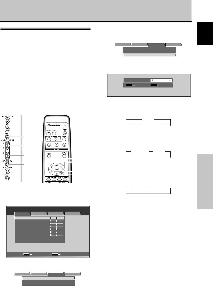
3Use the 5/∞ buttons to select [SIGNAL FORMAT], then press the SET button.
|
MENU |
|
INPUT1 |
|
PICTURE SCREEN |
SETUP |
OPTION |
|
POWER MANAGEMENT : OFF |
|
|
|
CLAMP POSITION |
: AUTO |
|
|
SIGNAL FORMAT |
: V G A |
|
|
|
|
|
4 Use the 2/3 buttons to select the display mode.
SIGNAL FORMAT : |
VGA |
SET SET |
MENU EXIT |
1When the input signal has a refresh rate of 31.5 kHz horizontal / 60 Hz vertical, pressing 2/3 causes the display mode to toggle between the following options:
3 VGA 2
3 WVGA 2
MENU
5/∞
2/3
MENU
2/3
SET
 SET
SET
5/∞
Main unit operating |
Remote control unit |
panel |
|
2When the input signal has a refresh rate of 48.4 kHz horizontal / 60 Hz vertical, or 56.1 kHz horizontal / 70 Hz vertical, pressing 2/3 causes the display mode to cycle through the following options:
3 PC AUTO 2 3 XGA 2
3 WXGA 2
3When the input signal has a refresh rate of 64 kHz horizontal / 60 Hz vertical, 80 kHz horizontal / 75 Hz vertical, or 91.2 kHz horizontal / 85 Hz vertical, pressing 2/3causes the display mode to toggle between the following options:
3 SXGA 2 3 SXGA+ 2
1 Press the MENU button to display the menu
screen. |
|
|
|
|
MENU |
|
|
|
INPUT1 |
PICTURE |
SCREEN |
SETUP |
OPTION |
|
CONTRAST |
|
: |
0 |
|
BRIGHTNESS |
: |
0 |
|
|
R.LEVEL |
|
: |
0 |
|
G.LEVEL |
|
: |
0 |
|
B.LEVEL |
|
: |
0 |
|
H.ENHANCE |
: |
0 |
|
|
V.ENHANCE |
|
: |
0 |
|
PICTURE RESET |
|
|
|
|
SET |
ENTER |
|
MENU |
EXIT |
2 Use the 2/3 buttons to select [SETUP].
|
MENU |
|
INPUT1 |
|
PICTURE SCREEN |
SETUP |
OPTION |
|
POWER MANAGEMENT : OFF |
|
|
|
CLAMP POSITION |
: AUTO |
|
|
SIGNAL FORMAT |
: V GA |
|
|
|
|
|
If the [PC AUTO] setting is selected when using the above PC input signals, screen resolution automatically switches between [XGA] and [WXGA].
Reminders
÷The [PC AUTO] setting supports automatic signal selection only when using separate RGB SYNC inputs.
÷When G ON SYNC or Composite SYNC signals are input, selecting [PC AUTO] causes the screen resolution to be set to [XGA] only.
÷When using G ON SYNC or Composite SYNC with WXGA inputs, manually set the [SIGNAL FORMAT] to [WXGA].
5Press the SET button.
The setting is stored in memory and the screen returns to that shown in step 3.
6When the setup is completed, press the MENU button to exit the menu screen.
Note:
Set [SIGNAL FORMAT] for each input (INPUT1 and INPUT2).
17
En
English
System Settings
English
System Settings
System Settings
[CLAMP POSITION] setup
Depending upon the signal, analog RGB signals may cause a screen image to appear with a whitish or greenish cast. In such cases, set [CLAMP POSITION] to [LOCKED]. Normally, leave this setting at [AUTO].
MENU
5/∞
2/3
MENU
2/3
SET
 SET
SET
5/∞
3 Use the 5/∞ buttons to select [CLAMP POSITION].
MENU |
|
INPUT1 |
PICTURE SCREEN |
SETUP |
OPTION |
POWER MANAGEMENT : OFF |
|
|
CLAMP POSITION |
: AUTO |
|
SIGNAL FORMAT |
: V G A |
|
SET CHANGE |
MENU EXIT |
4Press the SET button to select [LOCKED].
The factory default setting is [AUTO].
Pressing the SET button causes the setting to toggle between the following options:
3 AUTO
LOCKED 2
5When setup is complete, press the MENU button to exit the menu screen.
Main unit operating |
Remote control unit |
panel |
|
1 Press the MENU button to display the menu.
MENU |
|
|
|
INPUT1 |
PICTURE |
SCREEN |
SETUP |
OPTION |
|
CONTRAST |
|
: |
0 |
|
BRIGHTNESS |
: |
0 |
|
|
R.LEVEL |
|
: |
0 |
|
G.LEVEL |
|
: |
0 |
|
B.LEVEL |
|
: |
0 |
|
H.ENHANCE |
: |
0 |
|
|
V.ENHANCE |
|
: |
0 |
|
PICTURE RESET |
|
|
|
|
SET |
ENTER |
|
MENU |
EXIT |
Reminders
÷The [CLAMP POSITION] setting is supported only for INPUT1.
÷When setting this option, confirm that the component's signal output is used. For details, consult the device’s Operating Instructions.
2 Use the 2/3 buttons to select [SETUP].
|
MENU |
|
INPUT1 |
|
PICTURE SCREEN |
SETUP |
OPTION |
|
POWER MANAGEMENT : OFF |
|
|
|
CLAMP POSITION |
: AUTO |
|
|
SIGNAL FORMAT |
: V GA |
|
SET |
CHANGE |
MENU |
EXIT |
18
En
Operation
Selecting An Input Source
This section explains basic operation of this panel.
Outlined on the following pages is how to turn the main power ON and OFF, how to operate the unit, when the unit should be put in Standby mode, and how to select connected devices.
Before you begin, verify the following:
¶Check connections between the panel and the computer as described in “Installation and Connections" starting on page 10.
¶Set up the on-screen menu to input signals from devices connected to INPUT1 and INPUT2 as
described in “System Settings” starting on page 16.
On-screen setup is not necessary if these terminals are not being used.
STANDBY/
ON 


 STANDBY/ ON
INPUT
INPUT
 VOLUME [+/–]
VOLUME [+/–]
Main unit operating |
Remote control unit |
panel |
|
1Set the rear panel MAIN POWER switch to ON.
The STANDBY indicator on the front panel lights red.
2Press the STANDBY/ON button to turn power ON.
The ON indicator on the front panel lights green.
3Press the INPUT button on the remote control unit
or the main unit to select the input.
Pressing the INPUT button causes the display to toggle between the following options:
3INPUT1 INPUT2 2
÷When the menu screen is displayed, changing the signal input caused the menu screen to turn OFF.
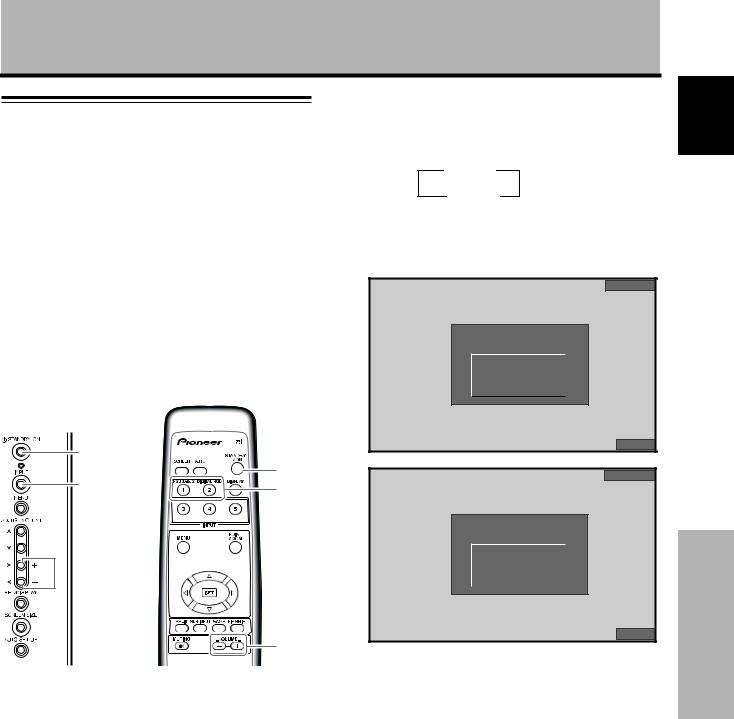
÷If the input computer signal is not supported by the display, the following message appears:
INPUT1
CAUTION
UNSUPPORTED SIGNAL
f H : |
8 6 . |
7 |
k H z |
f V : |
8 8 . |
5 |
H z |
1 1 |
5 2 X 8 6 |
4 |
|
FULL
INPUT1
CAUTION
OUT OF RANGE
f H : 7 5 . |
7 k H z |
f V : 1 2 0 . |
0 H z |
– – – – |
|
|
|
FULL
4Use VOLUME (+/–) buttons on the remote control
unit or the main unit to adjust the sound volume.
If no audio connections are made to this unit, this step is not necessary.
5When viewing is finished, press the STANDBY/ON button to put the unit in standby mode.
6Set the rear panel MAIN POWER switch to OFF.
The STANDBY indicator may continue to light for a short while even after the main power is turned OFF. This is a result of residual electricity impressed on the circuitry. The light turns off after a short period.
Note
Please do not leave the same picture displayed on the screen for a long time. Doing so may cause a phenomenon known as
“screen burn” which leaves a ghost or residual image of the picture on the screen.
English
Operation
19
En
English
Operation
Adjusting sound volume
Confirming current status
Operation
VOLUME [+/–]
 VOLUME [+/–]
Remote control unit
Main unit operating panel
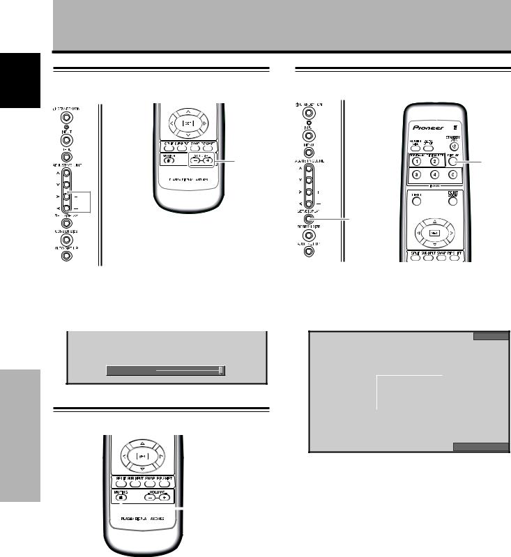
Press the VOLUME buttons.
Press the [–] or [+] button to decrease or increase the volume of sound from the speakers.
VOLUME : 5

Muting the sound
 MUTING
DISPLAY
DISPLAY
Main unit operating panel |
Remote control unit |
Press the DISPLAY button.
The currently selected input, screen size, and refresh rates appear for approximately 3 seconds.
INPUT1
f H : |
3 1 . |
5 |
k H z |
f V : |
6 0 . |
0 |
H z |
6 4 0 X 4 8 |
0 |
||
|
|
|
|
DOT BY D OT
Reminders
¶The displayed refresh rates may be slightly different from the actual values.
¶When using the Point Zoom function (page 22) or Multiscreen function (page 23), the position and input information for the enlarged screen area are displayed.
¶When the screen management function is active, the
[SCREEN MGT.] message also appears in the lower left corner of the screen.
Press the MUTING button on the remote control. Press the MUTING button again to restore the sound.
Muting is automatically canceled approximately 8 minutes after the button is pressed. The volume level then adjusts to the minimum level.
Press VOLUME + or VOLUME – to adjust the volume to a desired level.
20
En
Operation
Changing screen size
This panel incorporates screen modes of various height and width ratios. For optimal viewing, we recommend selecting the screen mode that best matches the video source that you are viewing. Although these modes are designed for full display of a picture on a wide screen, it is our hope that you make use of them with the full understanding of our intentions.
Screen size selection
There are four display modes. Select the mode that best shows the size and range of the image.
Press the SCREEN SIZE button to select the size.
SCREEN
SIZE
Remote control unit
SCREEN SIZE
Main unit operating panel
Pressing the SCREEN SIZE button causes the view to cycle through the following options:
[PDP-505CMX/PDP-504CMX]
3 DOT BY DOT |
3 PARTIAL |
FULL 2 |
4:3 2 |
or |
4:3 2 |
FULL 2 |
[PDP-434CMX]
3 DOT BY DOT |
3 4:3 |
or |
|
3 ZOOM |
|
|
||||
|
FULL 2 |
|
|
|
FULL 2 |
|
4:3 2 |
|
||
|
|
|
|
|
|
|||||
|
|
|
|
|
|
|
|
|
|
|
Consult the Computer Signal Compatibility table (pages 38 to 41) for information regarding screen sizes supported by each signal format.
Reminders
÷When the [PARTIAL], [ZOOM] or [FULL] setting is used to display a non-wide screen 4:3 picture fully on a wide screen, a portion of the picture may be cut off or appear deformed.
÷Be aware that when the display is used for commercial or public viewing purposes, selecting the [PARTIAL], [ZOOM] or [FULL] mode settings may violate the rights of the authors protected under copyright law.
÷When [DOT BY DOT] or [4:3] screen size is selected, the display position is moved slightly each time the power is turned ON in order to prevent image burning.
During personal computer signal input
1 DOT BY DOT
The input signal and the screen maintain a dot to line ratio of 1:1, thus is highly faithful to the source.
[PDP-505CMX/PDP-504CMX]
|
|
|
|
|
|
|
|
|
|
|
A |
|
|
|
|
|
|
|
|
|
|
480 lines |
|
|
|
||||
|
|
|
|
|
|||||
|
|
|
|
|
|
|
|
|
|
|
|
|
|
|
|
|
|
|
|
|
|
|
|
|
|
768 lines |
|||
|
|
|
|
|
|
|
|
|
|
 640 dots
1280 dots
(illustration shows 640 x 480 input)
[PDP-434CMX]
*The PDP-434CMX is designed with horizontally oblong elements, resulting in a image that appears more oblong than the original input signal.
|
|
|
|
|
|
|
|
|
|
|
|
A |
|
|
|
|
|
|
|
|
|
|
|
480 lines |
|
|
|
|||||
|
|
|
|
|
||||||
|
|
|
|
|
|
|
|
|
|
|
|
|
|
|
|
|
|
768 lines |
|||
|
|
|
|
|
|
|
|
|
|
|
|
|
|
|
|
|
|
|
|
|
|
 640 dots
1024 dots
(illustration shows 640 x 480 input)
2 4:3
The display fills the screen as much as possible without altering the aspect ratio of the input signal.

 A
A 

3 FULL
The display is shown with a widescreen aspect ratio of 16:9 and fills the entire screen.
A
21
English
Operation
En
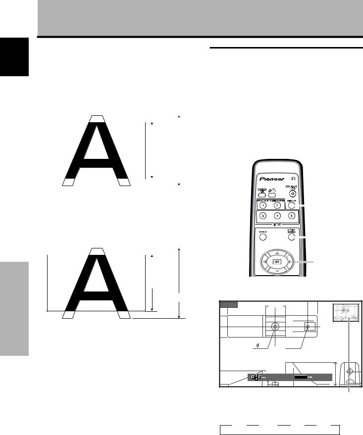
English
Operation
Operation
4 PARTIAL |
Enlarging one part of the screen |
|
||||||||||||||
*Supported only on PDP-505CMX/PDP-504CMX |
||||||||||||||||
The [PARTIAL] setting is available only during input from |
(POINT ZOOM) |
|||||||||||||||
a computer (1280 x 1024 input only). |
|
|
|
|
|
|||||||||||
The input signal and the screen maintain a dot to line ratio |
This panel allows enlarging of the screen image by ratios |
|||||||||||||||
of 1:1; the appearance is highly faithful to the source. |
of [x 1.5], [x 2], and [x 3]. When enlarging the display |
|||||||||||||||
However, to maintain the 1:1 ratio, a portion of the display |
5 ∞ 2 3 |
buttons can be used to move the |
||||||||||||||
does not appear on the screen. |
screen, the / / / |
|||||||||||||||
enlarged viewing area around the screen. |
||||||||||||||||
|
|
|
|
|
|
|
|
|
|
|
|
¶ The possible zoom range can be confirmed by viewing the |
||||
|
|
|
|
|
|
|
|
|
|
|
|
|||||
|
|
|
|
|
|
|
|
|
|
|
|
Zoom-Area subscreen at the upper right of the main screen. |
||||
|
|
|
|
|
|
|
|
|
|
|
|
|||||
|
|
|
|
|
|
|
|
|
|
|
|
The Zoom-Area subscreen appears for approximately 3 |
||||
|
|
|
|
|
|
|
|
|
|
|
|
seconds whenever the POINT ZOOM button, the DISPLAY |
||||
|
|
768 lines |
|
|
|
|
button or one of the 5/∞/2/3 buttons is pressed. |
|||||||||
|
|
|
|
|
|
|
|
|
|
|||||||
|
|
|
|
|
|
|
|
|
|
|
|
|
|
|
|
|
|
|
|
|
|
|
|
|
|
|
|
|
|
|
|
|
|
|
|
|
|
|
|
|
1024 lines |
|
|
|
|
|
|
|||
|
|
|
|
|
|
|
|
|
|
|
|
|
|
|
|
|
|
|
|
|
|
|
|
|
|
|
|
|
|
||||
Use the 5/∞ buttons to adjust the vertical position of the |
|
|
|
|
|
|||||||||||
video image on the screen. |
|
|
|
DISPLAY |
||||||||||||
5 ZOOM (*Supported only on PDP-434CMX) |
|
|
|
|||||||||||||
|
|
|
||||||||||||||
|
|
|
|
|
||||||||||||
The [ZOOM] setting is available only during input from |
|
|
|
|
|
|||||||||||
a computer (1280 x 1024 input only). |
|
|
|
POINT |
||||||||||||
A portion of the display does not appear on the screen. |
|
|
|
|||||||||||||
|
|
|
ZOOM |
|||||||||||||
|
|
|
|
|
|
|
|
|
|
|
|
|
|
|
||
|
|
|
|
|
|
|
|
|
|
|
|
|
|
|
5/∞/2/3 |
|
|
|
|
|
|
|
|
|
|
|
|
|
|
|
|
||
|
|
|
|
|
|
|
|
|
|
|
|
|
|
|
||
|
|
|
|
|
|
|
|
|
|
|
|
|
|
|
|
|
768 lines |
1 Press the remote control’s POINT ZOOM button. |
|||
1024 lines |
|
|
|
|
|
x 1.5 |
66.0 |
|
|
Use the 5/∞ buttons to adjust the vertical position of the |
|
|
|
|
video image on the screen. |
|
|
|
|
Moving the screen position |
|
24 |
R12 |
|
|
|
|
|
|
upward or downward |
|
|
|
|
Press the 5/∞ buttons. |
|
|
22.1 |
|
|
10SCROLL |
P.ZOOM |
ZOOM |
|
When playing a [PARTIAL] or [ZOOM] image (1280 x 1024 |
|
|
|
|
input only) from a computer, the vertical position of the |
|
|
Zoom-Area subscreen |
|
screen image can be adjusted. However, adjusted positions |
|
|
||
|
|
|
|
|
cannot be stored in memory. |
Pressing the POINT ZOOM button causes the zoom ratio |
|||
Note |
to cycle through the following options: |
|||
The image cannot be horizontally repositioned. |
3 OFF |
3 x 1.5 |
3 x 2 |
3 x 3 |
|
Reminders |
|
|
|
|
¶ While using the POINT ZOOM function, the screen size can- |
|||
|
not be changed. |
|
|
|
|
¶ When using a plasma display panel in a profit-making activity or |
|||
|
when exhibiting images publicly, using the screen size function |
|||
|
to compress or stretch the image may result in infringement of |
|||
|
the copyrights of the image's owner(s). |
|
||
22
En
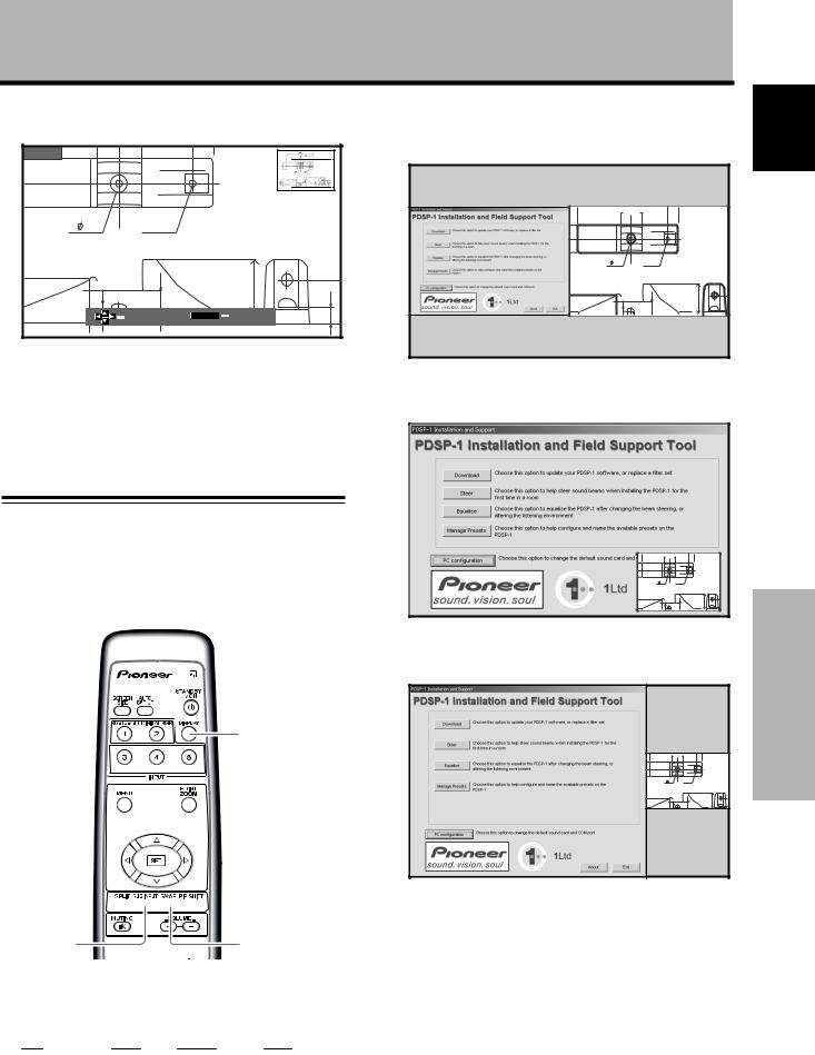
Operation
2Using the 5/∞/2/3 buttons, move the screen to the desired part of the image.
x 1.5 |
|
|
|
|
24 |
R12 |
|
|
|
|
22.1 |
|
|
|
|
|
|
10 |
50 |
|
SCROLL |
P.ZOOM |
ZOOM |
|
84.3 |
10 |
|
|
|
÷Pressing the POINT ZOOM and 5/∞/2/3 buttons again changes the zoom ratio and the position of the enlarged screen.
÷If the input signal changes, if input is changed through the menu screen, or if the multiscreen mode is chosen, the POINT ZOOM function is cancelled.
Multiscreen display
The panel’s multiscreen function allows the simultaneous display of two inputs. The multiscreen display includes three modes: 2-SCREEN, PinP, and PoutP.
DISPLAY
12-SCREEN
The main screen appears on the left and the subscreen shows on the right.
|
66.0 |
24 |
R12 |
|
22.1 |
|
10 |
2PinP
The subscreen appears in one of the four corners of the main screen.
|
66.0 |
24 |
R12 |
|
22.1 |
|
10 |
3PoutP
The subscreen appears beyond the right side of the main screen.
|
66.0 |
24 |
R12 |
|
22.1 |
|
10 |
English
Operation
SPLIT 


 PIP SHIFT
SUB INPUT |
SWAP |
1Press the remote control’s SPLIT button.
Pressing the SPLIT button causes the display to cycle through the following options:
|
3 2-SCREEN |
3 PinP |
3 PoutP |
3 OFF |
|
|
|
||||
|
|
|
|
|
|
2Press the remote control’s SUB INPUT button to select the subscreen input source.
To exchange the main screen and subscreen inputs
Press the remote control’s SWAP button.
¶ In 2-SCREEN mode:
The right and left sides of the display switch; what was previously the main screen becomes the subscreen and vice versa.
¶ In PinP or PoutP mode:
What was previously the main screen image appears in reduced size as the subscreen image and vice
versa. |
23 |
En
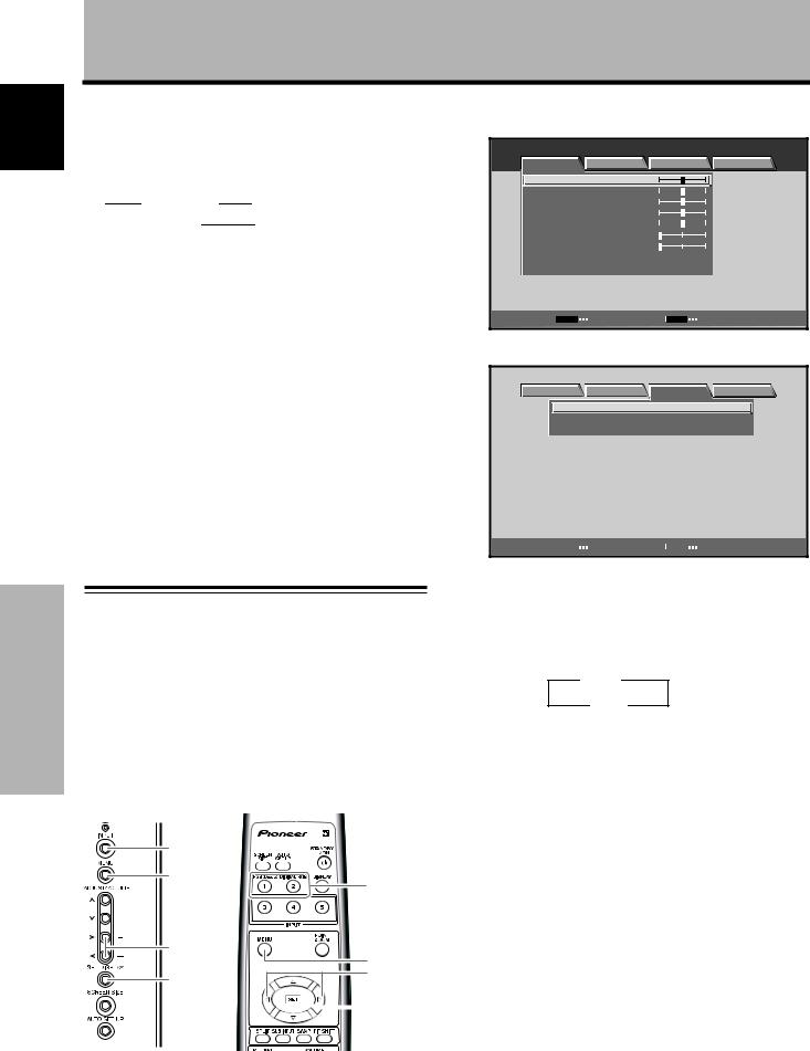
English
Operation
Operation
To change the position of the subscreen in PinP mode:
Press the remote control’s PIP SHIFT.
Each press of the PIP SHIFT button causes the position of the subscreen to move in the following direction:
|
3 Lower right |
3 Upper right |
|
|||
|
|
|||||
|
|
|
|
|
|
|
|
Lower left 2 |
|
|
Upper left 2 |
|
|
|
|
|
|
|||
To display the currently selected input,
press the DISPLAY button.
If the DISPLAY button is pressed while in multiscreen mode, the main screen and sub-screen each appear in its currently selected input.
Reminders
¶When using the panel in a profit-making activity, or when exhibiting images publicly, using the screen size function to compress or stretch the image may result in infringement of the copyrights of the image's owner(s).
¶If the multiscreen display is left on for an extended period of time or if the same multiscreen display is repeatedly shown for short periods on an everyday basis, a residual image pattern may be burned onto the screen.
¶When selecting the 2-SCREEN mode, the screen image may appear somewhat rougher depending upon the source.
¶The multiscreen mode is canceled if a menu is opened or if performing a POINT ZOOM.
¶The screen size cannot be changed during multiscreen display.
¶The sound of the input selected in the main menu is output when using the multiscreen function.
Automatic power-off (POWER MANAGEMENT)
This display is equipped with [POWER MANAGEMENT] which allows the unit to automatically switch to the Standby mode when no sync signal is detected.
(A warning message is displayed before this function operates.)
Note
Always turn off the plasma display’s main power switch when not using the panel for extended periods of time.
INPUT
MENU
INPUT
2/3
MENU
2/3
SET
 SET
SET
Main unit operating |
Remote control unit |
panel |
|
24
1 Press the MENU button to display the menu
screen. |
|
|
|
|
MENU |
|
|
|
INPUT1 |
PICTURE |
SCREEN |
SETUP |
OPTION |
|
CONTRAST |
|
: |
0 |
|
BRIGHTNESS |
: |
0 |
|
|
R.LEVEL |
|
: |
0 |
|
G.LEVEL |
|
: |
0 |
|
B.LEVEL |
|
: |
0 |
|
H.ENHANCE |
: |
0 |
|
|
V.ENHANCE |
|
: |
0 |
|
PICTURE RESET |
|
|
|
|
SET |
ENTER |
|
MENU |
EXIT |
2 Use the 2/3 buttons to select [SETUP].
|
MENU |
|
INPUT1 |
|
PICTURE SCREEN |
SETUP |
OPTION |
|
POWER MANAGEMENT : OFF |
|
|
|
CLAMP POSITION |
: AUTO |
|
|
SIGNAL FORMAT |
: V GA |
|
SET |
CHANGE |
MENU |
EXIT |
3Press the SET button to confirm selection of [POWER MANAGEMENT].
The factory default setting is [OFF].
Each time the button is pressed, the setting toggles
between OFF and ON.
3 OFF
ON 2
÷OFF ..... The panel continues in the operating mode, regardless of the presence/absence of an input sync signal.
÷ON ....... If a sync signal is not detected, a warning message appears for 8 seconds then the display automatically enters the Standby (*1), and the ON indicator flashes green. If a sync signal is input again later, the panel automatically returns to the normal
operating mode (*2).
*1. Power consumption about 0.8 W
*2. Except when input signal is G ON SYNC or
composite SYNC
4 When the setup is finished, press the MENU
button to exit the menu screen.
Note
The [POWER MANAGEMENT] function must be set individually for each input (INPUT1 / INPUT2).
To return to operating mode:
To return to normal operation from the [POWER MANAGEMENT] function’s Standby mode, either operate your computer or press the INPUT button (on the panel or using the remote control).
En
 Loading...