


Table top stand
Support de couverture de table Tischständer
Supporto di tavolo Tafelbladstaander Soporte de mesa


PDK-TS12
Operating instructions Mode d’emploi Bedienungsanleitung Istruzioni per l’uso Gebruiksaanwijzing Manual de instrucciones
|
|
................................................................. |
2 |
................................................. |
3 |
................................................. |
3 |
................................................. |
4 |
...................................... |
5 |
......................................................... |
6 |
.......................................... |
7 |
................................................. |
8 |
......................................................................... |
9 |
.......................................... |
9 |
........ |
10 |
.......................................................................... |
10 |
.......................................................................... |
10 |
|
|
取扱説明書および製品に記されている注意事項には、損害の レベルや内容を示す絵表示が付けられていることがありま す。それら絵表示の意味は以下のとおりです。
警告
注意


2
PDP-506HD/PDP-436HD/PDP-436SX

2
10 27 6
9
Ja
× 1
S ×2
PDP-436SX
L × 2
×1 |
C ×1 |
6mm |
10mm |
×2
1 M8×16mm ×4
2 |
×1 |
M8 ×30mm × 2 |
|
|
Table top stand |
|
Support de couverture de table |
|
Tischständer |
|
Supporto di tavolo |
|
Tafelbladstaander |
|
Soporte de mesa |
|
PDK-TS12 |
3 |
|
M8 ×40mm × 2 |
|
|
Operating instructions |
|
Mode d’emploi |
|
Bedienungsanleitung |
|
Istruzioni per l’uso |
|
Gebruiksaanwijzing |
|
Manual de instrucciones |
4 |
|
M8 ×60mm × 2 |
|
PDP-436SX |
|
|
|
S |
L |
|
|
||
|
|
|
|
||||
|
|
|
|
|
|||
|
PDP-506HD/PDP-436HD |
|
* |
|
|||
|
|
|
|
|
|
||
PDP-436SX |
|
|
|
||||
|
|||||||
|
|
|
|
|
|
||
|
|
PDP-S38/PDP-S37 |
|
* |
|||
|
|
|
|
|
|
||
PDP-506PU/PDP-436PU |
PDP-S39 |
|
|
||||
|
|
|
|
|
|
||
|
|
|
|
* |
|||
|
|
|
|
|
|
||
|
|
PDP-S38/PDP-S37 |
|
* |
|||
|
PDP-506PE/PDP-436PE |
|
|
|
|
||
PDP-S39 |
|
|
|||||
|
|
|
|
|
|
||
|
|
|
|
* |
|||
|
|
|
|
|
|
||
|
|
PDP-S38/PDP-S37 |
|
* |
|||
|
PDP-506PG/PDP-436PG |
|
|
|
|
||
PDP-S39 |
|
|
|||||
|
|
|
|
|
|
||
|
|
|
|
* |
|||
* |
|
|
3 |
||||
|
|
|
|
|
|
Ja |
|
|
2 1 |
|
|
4 |
|
|
|
|
|
|
|
|
1 |
S |
3 |
|
|
|
|
|
|
|
2 1 |
|
|
|
PDP-506HD /PDP-436HD |
|
S |
|
|
1 |
|
(M8 × 16mm ) |
S ( |
|
|
3 4 |
|
|
|
|
PDP-436SX |
|
|
|
L |
C |
S |
|
|
|
L |
|
4
Ja
|
50V |
32kg 43V |
26kg 43V PDP-436SX 32kg |
|
2 |
|
|
|
|
|
|
|
|
1 |
|
|
|
|
|
|
|
2 2 |
|
S |
2 |
(M8 × 30mm ) |
L |
|
|
|
2 |
|
(M8 × 30mm ) |
|
3 3 4 |
|
|
|
|
|
|
|
PDP-506HD/PDP-436HD |
…… 3 M8×40mm |
PDP-436SX |
…… 4 M8×60mm |
|
|
|
PDP-506HD/PDP-436HD |
3 (M8× 40mm ) |
PDP-436SX |
4 |
(M8 × 60mm ) |
4 |
5
Ja

|
|
|
2 |
3 2 |
|
|
||
C |
||
|
||
|
|
|
|
|
|
|
||
|
||
|
||
|
|
|
|
||
|
||
|
|
|
1 C |
|
|
|
||
2 |
|
|
|
|
|
C |
|
|
|
|
|
PDP-436HD |
|
|
|
4 |
|
|
||
|
||
|
||
2 |
|
|
|
|
|
|
|
2˚
2˚
6
Ja

す場合」10

PDP-506HD/PDP-436HD
PDP-436SX
|
|
|
|
|
|
|
|
|
|
|
|
|
|
||||
|
|
|
|
||
|
|
|
|
|
|
30mm |
|
30mm |
|
|
|
|
|
10mm |
|
420mm |
|
|
|
|
|
|
|
|
30mm |
|
|
|
|
|
|
|
|
|
|
かしてください。

˚ 10
10
˚ 10
10
7
Ja
|
|
|
|
|
|
|
1 |
|
|
|
|
|
|
|
PDP-506HD/PDP-436HD |
|
|
|
2 |
|
|
|
|
PDP-436SX |
|
|
3
が外れます。
8
Ja
43V
|
|
1 |
||
|
|
|
||
|
|
|
(2 |
|
915mm |
6mm |
|
||
|
||||
|
|
|||
|
|
PDP-506HD / PDP- |
||
M6 20mm |
|
|
||
|
|
436HD /PDP436SX |
||
|
|
|
||
|
|
|
||
|
20mm |
|
||
2
もって設定してください。
mm
552 (PDP-506HD) |
|
552 (PDP-506HD) |
478 (PDP-436HD/PDP-436SX) |
120 |
478 (PDP-436HD/PDP-436SX) |
|
|
24 |
|
|
356 |
1
2
呼び径M4 20 30mm
712mm
4mm
20 30mm
9
Ja
5
2 かせるスペースを作り、キズおよび破損が生じ6
3
4 52 3 4
4 2 M8 ×16mm
PDP-506HD/PDP- 436HD
PDP-436SX
2
|
577 ( )×249.5 ( ) ×380 ( ) mm S |
|
10.5 kg |
mm
PDP-506HD/PDP-436HD
1407 |
(PDP-506HD ) *1 |
1379 |
(PDP-506HD ) *2 |
1259 |
(PDP-436HD ) *1 |
1231 |
(PDP-436HD ) *2 |
/ 632 (PDP-436HD) |
|
706 (PDP-436HD) |
717 (PDP-506HD) |
80 |
791 (PDP-506HD) / |
|
140 |
|
577
L 853 (PDP-506HD)/ 768 (PDP-436HD)
*1 15mm
*2
10
92
23
125.1
162.9
380
Ja
PDP-506P/PDP-436P
|
1224 (PDP-506P) / 1076 (PDP-436P) |
|
/ 632 (PDP-436P) |
|
706 (PDP-436P) |
717 (PDP-506P) |
80 |
791 (PDP-506P) / |
|
140 |
|
577
L 853 (PDP-506P)/768 PDP-436P)
PDP-436SX
1076
696 |
768.5 |
|
80 |
|
202 |
|
577 |
92
23
125.1
162.9
380
116
23
104.1
159.9
380
2005
11
Ja
Thank you for buying Pioneer’s product.
Please read through the Operating Instructions to learn how to operate your model safely and properly.
Please be advised to keep the Operating Instructions in your place for future reference.
IMPORTANT NOTICE – RECORD THE MODEL NUMBER AND SERIAL NUMBERS OF THIS EQUIPMENT BELOW. THE NUMBERS ARE ON THE REAR.
MODEL NO.
SERIAL NO.
KEEP THESE NUMBERS FOR FUTURE USE.
D1-4-2-6-2_En
Installation
¶Consult your dealer if you encounter any difficulties with this installation.
¶Pioneer is not liable for any damage resulting from improper installation, improper use, modification, or natural disasters.
Contents |
|
Cautions ................................................................. |
12 |
Checking the Enclosed Parts ................................ |
13 |
Support Columns Used / Not Used Table .......... |
13 |
Assembling the Stand .......................................... |
14 |
Attaching the Plasma Display .............................. |
15 |
Forward/Backward Angle of Inclination |
|
Adjustment Mechanism ....................................... |
16 |
Installing the Product on a Rack etc.................... |
17 |
Preparing the Cables............................................. |
18 |
Preventing Equipment from Falling Over ........... |
19 |
Fixing the rotation to the front ............................ |
20 |
Detaching the Plasma Display from the Stand .... |
20 |
Specifications ........................................................ |
20 |
Dimensions Diagram ............................................ |
21 |
 CAUTION
This symbol refers to a hazard or unsafe practice which can result in personal injury or property damage.
Cautions
This product is a table top stand exclusively designed for Plasma Displays (PDP-5060HD / PDP-4360HD / PDP-506XDE / PDP-436XDE / PDP-506FDE / PDP-436FDE / PDP-506HDG / PDP-436HDG) from Pioneer.
Use with other model is capable of resulting in instability causing possible injury. For further information, please contact the store where you purchased your display.
Do not install or modify the product other than specified. Do not use this stand for a Plasma Display other than those designated and do not modify it or use it for other purposes.
Improper installation is extremely dangerous because it may result in it falling over or other accident.
Installation Location
•Select a location that is strong enough to support the weight of the stand and the displays.
•Make sure to place it in a level and stable location.
•Do not install it outdoors or in a wet place such as at a hot spring or near a beach.
•Do not install the stand where it may be subjected to vibration or shock.
Assembling and Installation
•Assemble the stand in accordance with the assembly instructions and securely attach all screws at the designated locations.
There have been cases where unforeseen accidents such as the equipment breaking or falling over occurred after the installation of the display because the stand was not installed as instructed.
•The display must always be installed by two or more people to assure it is installed safely.
•Before installation, turn off the power for the display and peripheral devices then remove the power cord plug from the power outlet.
This product rotates 10° to the left and right and inclines approximately 2° forward and backward.
Do not place objects within the range of rotation of this product and the Plasma Display. Install this product so that during routine use or when it is rotated, it does not protrude from the rack or other location it has been installed. Failure to do so could cause unforeseen accidents such as the equipment breaking or falling over (see page 17).
While adjusting its angle forward and backward, be extremely careful to keep your hands out of the space between the bottom of the plasma display and the stand (see page 16).
Prevent accidents caused by the product falling over during an earthquake etc., by taking reliable measures to prevent it from falling over (see page 19).
12
En
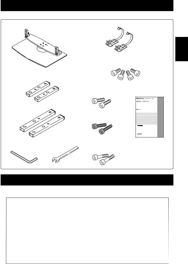
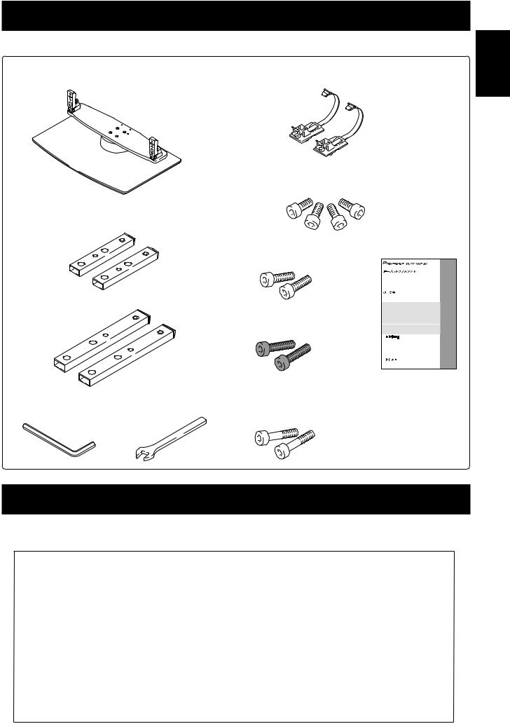
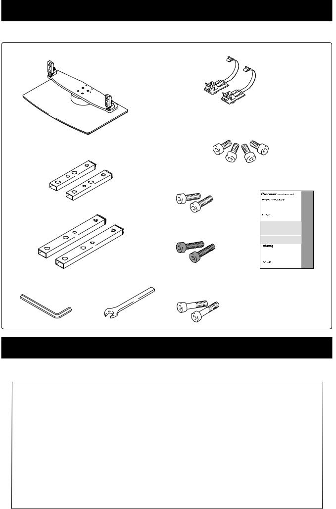
Checking the Enclosed Parts
Check to make sure that you have all the enclosed parts before assembly and installation.
Table top stand x 1 |
Cable binders x 2 |
Installation screws 1 (M8 x 16 mm: silver) x 4
[used to anchor the support columns and the table top stand]
Support columns S x 2 [short columns]
*Cannot be used to install the PDP-S39.
Installation screws 2 |
Operating instructions |
(M8 x 30 mm: silver) x 2 |
(this document) x 1 |
|
Table top stand |
|
Support de couverture de table |
|
Tischständer |
Support columns L x 2 |
Supporto di tavolo |
Soporte de mesa |
|
|
Tafelbladstaander |
[long columns] |
PDK-TS12 |
Installation screws 3 (M8 x 40 mm: black) x 2
Operating instructions
Mode d’emploi
Bedienungsanleitung
Istruzioni per l’uso
Gebruiksaanwijzing
Manual de instrucciones
English |
Hexagonal wrench x 1 |
C wrench x 1 (10 mm) |
Installation screws 4 |
(Diagonal size: 6 mm) |
|
(M8 x 60 mm: silver) x 2 |
|
|
*Can be used to install the PDP-436SX. |
Support Columns Used / Not Used Table
The support columns of this stand vary depending on the Plasma Display and speakers you have purchased. Please select the support columns according to the following table.
Your home region |
Product you purchased |
Support columns S |
Support columns L |
||
Plasma Display |
Speaker |
(short columns) |
(long columns) |
||
|
|||||
|
PDP-506HD / PDP-436HD |
Recommended |
*Can be used |
||
Japan |
|
|
|
|
|
PDP-436SX |
(Integrated Plasma |
Cannot be used |
Used |
||
|
Display and speakers) |
||||
|
|
|
|
||
|
|
PDP-S38 / PDP-S37 |
Recommended |
*Can be used |
|
North America |
|
|
|
|
|
PDP-506PU / PDP-436PU |
PDP-S39 |
Cannot be used |
Used |
||
|
|
|
|
|
|
|
|
Without speakers |
Recommended |
*Can be used |
|
|
|
PDP-S38 / PDP-S37 |
Recommended |
*Can be used |
|
Europe |
PDP-506PE / PDP-436PE |
PDP-S39 |
Cannot be used |
Used |
|
|
|
|
|
|
|
|
|
Without speakers |
Recommended |
*Can be used |
|
|
|
|
|
|
|
Other than Japan, |
|
PDP-S38 / PDP-S37 |
Recommended |
*Can be used |
|
North America, and |
PDP-506PG / PDP-436PG |
PDP-S39 |
Cannot be used |
Used |
|
Europe |
|
|
|
|
|
|
Without speakers |
Recommended |
*Can be used |
||
|
|
||||
|
|
|
|
|
|
*: Can be used when the screen is located in a high position.
13
En
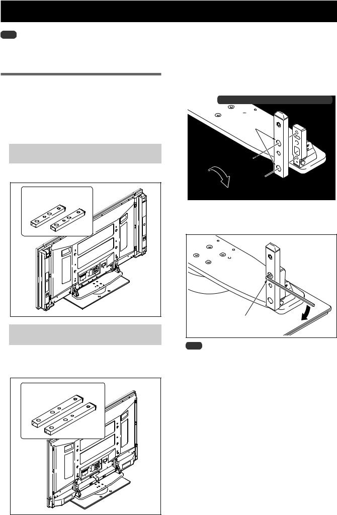
Assembling the Stand
Note
Always assemble it on a flat table etc.
Insert the screws in the holes vertically and do not tighten them with more force than necessary.
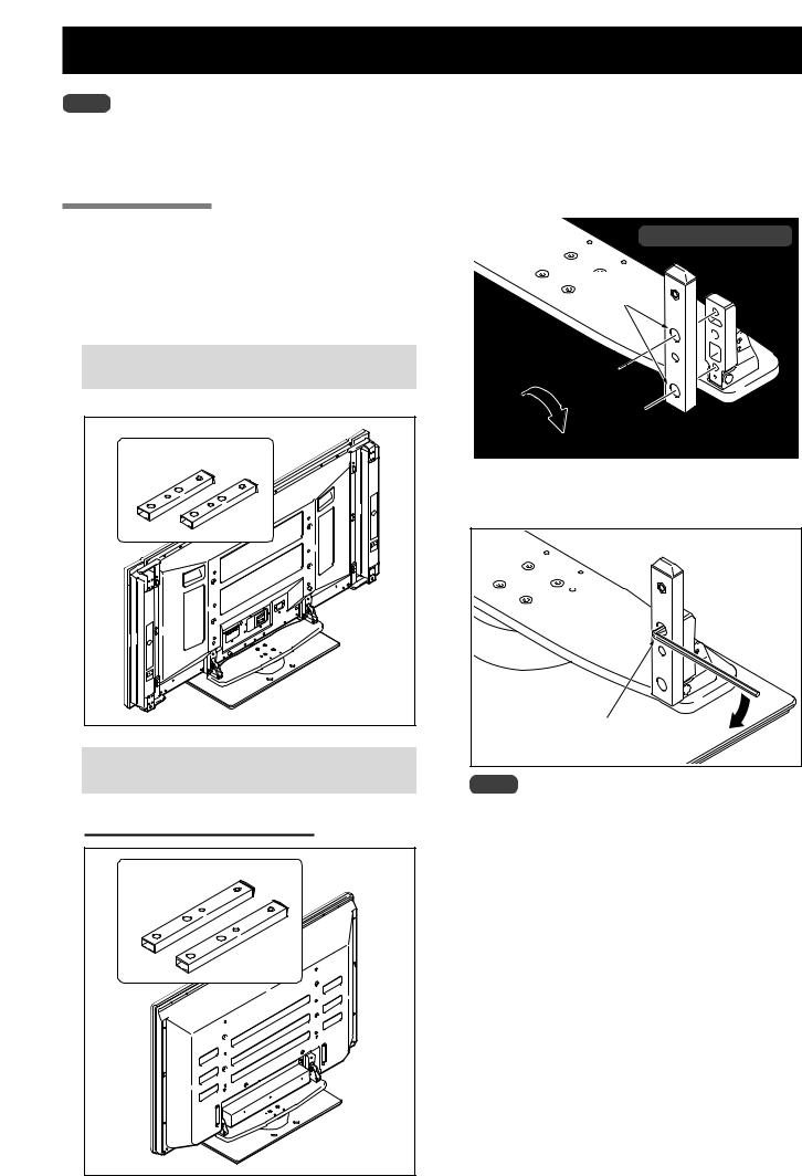
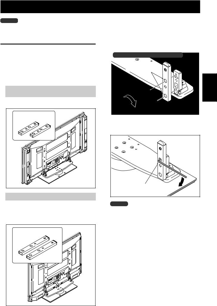
Assembly Procedure
1Select the support columns to attach (see “Support Columns Used / Not Used Table” on Page 13).
Select the support columns according to the speakers that you have purchased with reference to the following stipulation (Only one type of the two types of available support columns should be used).
2Secure the support column to the stand with the Installation screws 1 (4 locations on the left and right).
Using the enclosed hexagonal wrench, first loosely attach the top attachment screw, then loosely attach the bottom attachment screw.
Illustration: when using support columns S
The larger holes are on the front.
When the speakers you have purchased are
PDP-S38 or PDP-S37.
[Support column used: support column S (short columns)]
Support column used: |
Installation screws 1 |
|
(M8 x 16 mm: silver) |
||
support column S |
||
|
||
(short columns) |
|
|
|
3 Fully tighten the Installation screws |
|
|
(4 locations on the left and right). |
|
|
Fully tighten the attachment screws. |
When the speakers you have purchased are
PDP-S39.
[Support column used: support column L (long columns)]
Support column S (short columns) cannot be used.
Note
Be sure to carefully store the unused support columns, the hexagonal wrench, the C wrench, and the Operating Instructions together.
Support column used: |
support column L |
(long columns) |
14
En

Attaching the Plasma Display
The weight of a 50 inch Plasma Display (without speakers) is about 32 kg (70.5 lbs), that of a 43 inch
Caution model (without speakers) is about 26 kg (57.3 lbs), they have no depth, and are unstable. Therefore, at
least two people must assemble and install them.
Note
Be sure to install it on a flat stable location.
Insert the screws in the holes vertically and do not tighten them with more force than necessary.
Make sure that you install the support columns reliably according to the settings of the type of speakers you have purchased with reference to the procedure in “Assembling the Stand”.
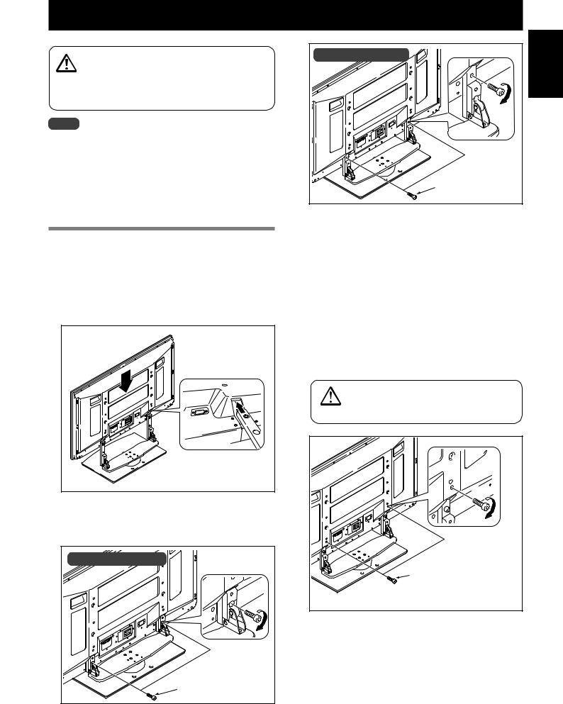
Attachment Method
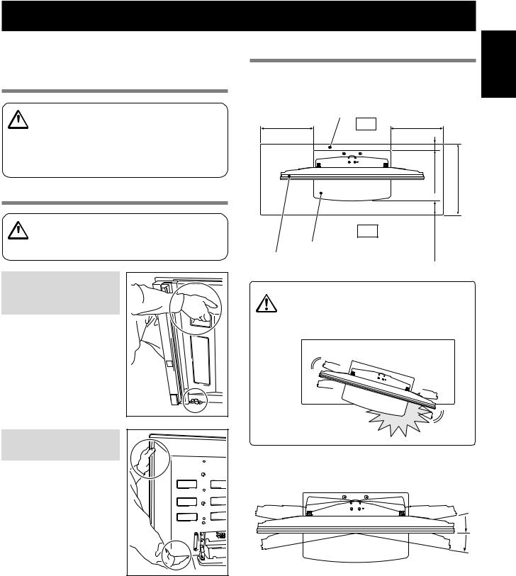
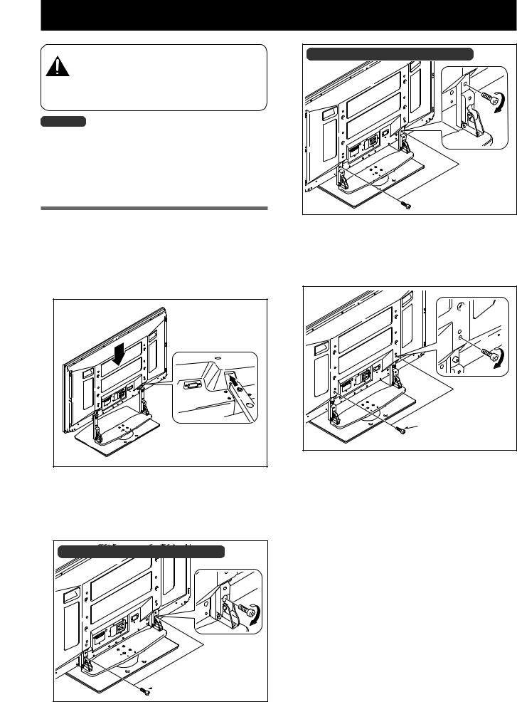
1 Attaching the Plasma Display to the stand.
Fit the stand’s support columns to the bottom of the Plasma Display as indicated by the arrows, then slowly insert them vertically. Be extremely careful not to insert the support columns of the stand into any part of the Plasma Display other than the stand insertion slots. Note that doing so might damage the Plasma Display panel or its ports or result in the warping of the stand.
Line up the column supports with the bottom of the Plasma Display as indicated in the accompanying diagram.
2Securing the Plasma Display with Installation screws 2.
Secure them using the enclosed hexagonal wrench.
Illustration: when using support columns S |
Installation screws 2 |
(M8 x 30 mm: silver) |
Illustration: when using support columns L |
English |
Installation screws 2 |
(M8 x 30 mm: silver) |
3Securing the Plasma Display with Installation screws 3.
Attach the Plasma Display at the points indicated by the arrows using the enclosed hexagonal wrench.
Installation screws 3 |
(M8 x 40 mm: black) |
4 Attaching the speakers.
Refer to the operating instructions for the speaker for the installation method.
15
En
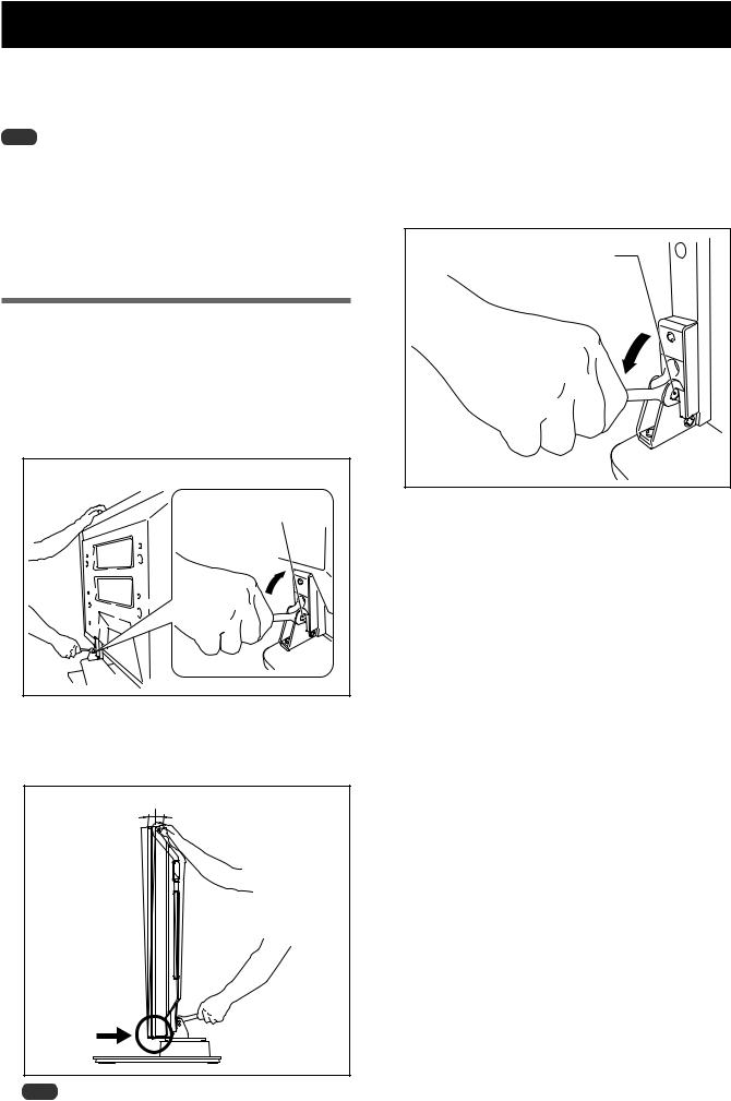
Forward/Backward Angle of Inclination Adjustment Mechanism
On this stand, you can adjust the angle of inclination of the Plasma Display within a range of approximately 2° forward or backward according to your preference.
Note
Be sure to adjust the angle only after you have attached the Plasma Display.
Be sure to install it on a flat table or other flat surface.
Be sure to hold the top of the Plasma Display with your hand while adjusting the angle.
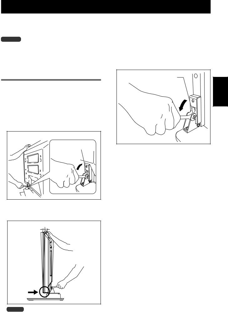
Adjustment Procedure
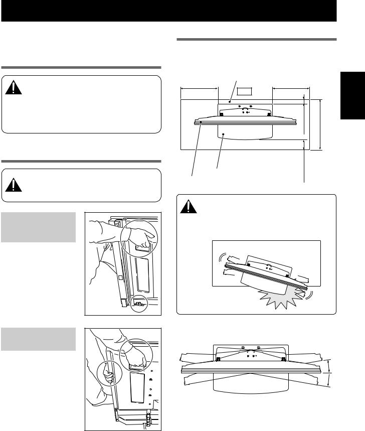
1Loosen the forward/backward inclination anchor bolts using the enclosed C wrench (2 locations on the left and right).
While being sure to hold the top of the Plasma Display with your hand, loosen the forward/backward inclination anchor bolts on the left and right sides by rotating them upwards using the enclosed C wrench.
*Figure shows the 43 inch display model.
Forward/backward inclination anchor bolt
Loosening
3Tighten the forward/backward inclination anchor bolts (2 locations on the left and right).
Firmly tighten the forward/backward inclination anchor bolts on the left and right sides by rotating them downward using the enclosed C wrench.
Be sure to hold the top of the Plasma Display with your hand until you have fully tightened the bolts.
Forward/backward inclination anchor bolt
Tightening
4Check once more to make sure that the forward/backward inclination anchor bolts are fully tightened.
2 Set the angle you prefer.
Set the angle you prefer by slowly moving the Plasma Display.
2˚
2˚
Note
While adjusting the angle, be very careful to keep your
hands out of the place indicated by the arrow on the figure.
16
En
Installing the Product on a Rack etc.
Be sure to observe the following precautions when moving or installing this product with a Plasma Display into a rack or other enclosure.
Precautions when moving
When moving the product more than a few meters, first remove the speaker, then remove
Caution
the Plasma Display from the stand and move the speaker, Plasma Display, and stand separately.
When detaching the Plasma Display from the stand, be sure to follow the procedure described in “Detaching the Plasma Display from the Stand” on page 20.
Precautions when installing in a rack or other enclosure
When installing in a rack or other enclosure, hold the Plasma Display by the handles located on the rear and bottom of the Plasma Display. If you hold the
Caution speakers, they may be damaged or twisted.
When installing the PDP-S38 or PDP-S37 speakers
Hold the Plasma Display by its handles and from the bottom.
Installation precautions
Make sure that you always secure a space at least as large as that shown in the following diagram in front of and behind the table top stand.
|
Rack |
mm10Min. |
inch)(13/32 |
racktheofDepth |
inch)9/16-(16mm420 |
recommendedmoreor |
English |
Min. 30 mm |
|
||||||
|
Min. 30 mm |
|
|
|
|
|
|
(1-3/16 inch) |
Back |
(1-3/16 inch) |
|
|
|
|
|
|
|
|
mm30Min. |
inch)3/16-(1 |
|
|
Front |
||
|
|
|
|
|
Table top stand |
|
|
|
|
Plasma Display |
|
|
|
|
If the stand protrudes from the rack, it could cause unforeseen accidents such as the equipment break-
Caution ing or falling over.
When rotating, take care not to allow the display to bump into walls or surrounding objects.
 Protrusion is dangerous.
When installing the |
Range of angle rotation |
|
|
PDP-S39 speaker |
|
Hold the Plasma Display by its handles and from the sides.
˚ 10
˚ 10
10
17
En
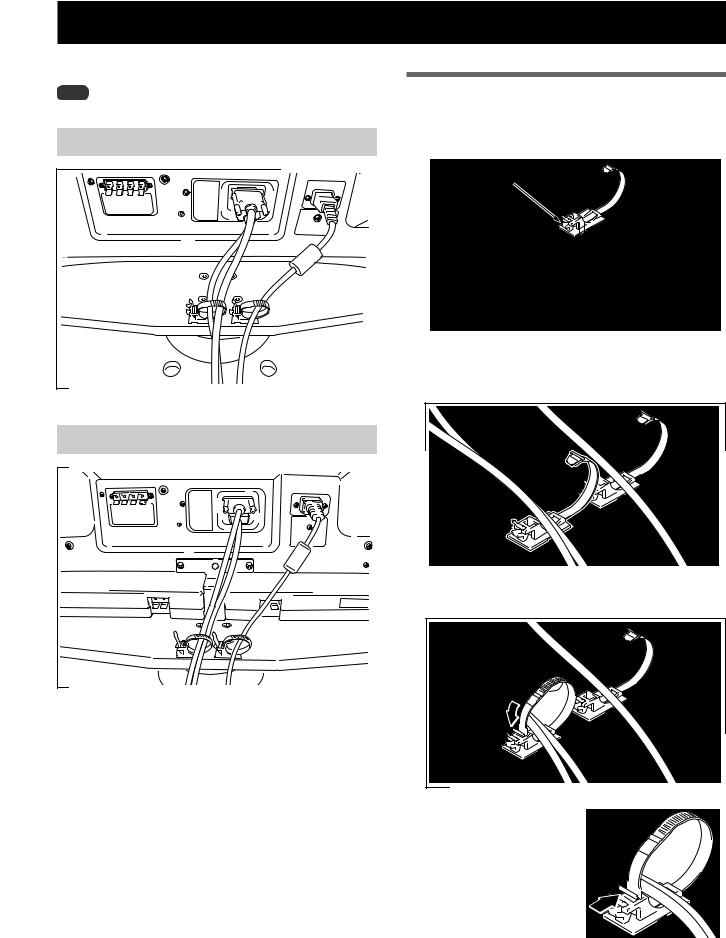
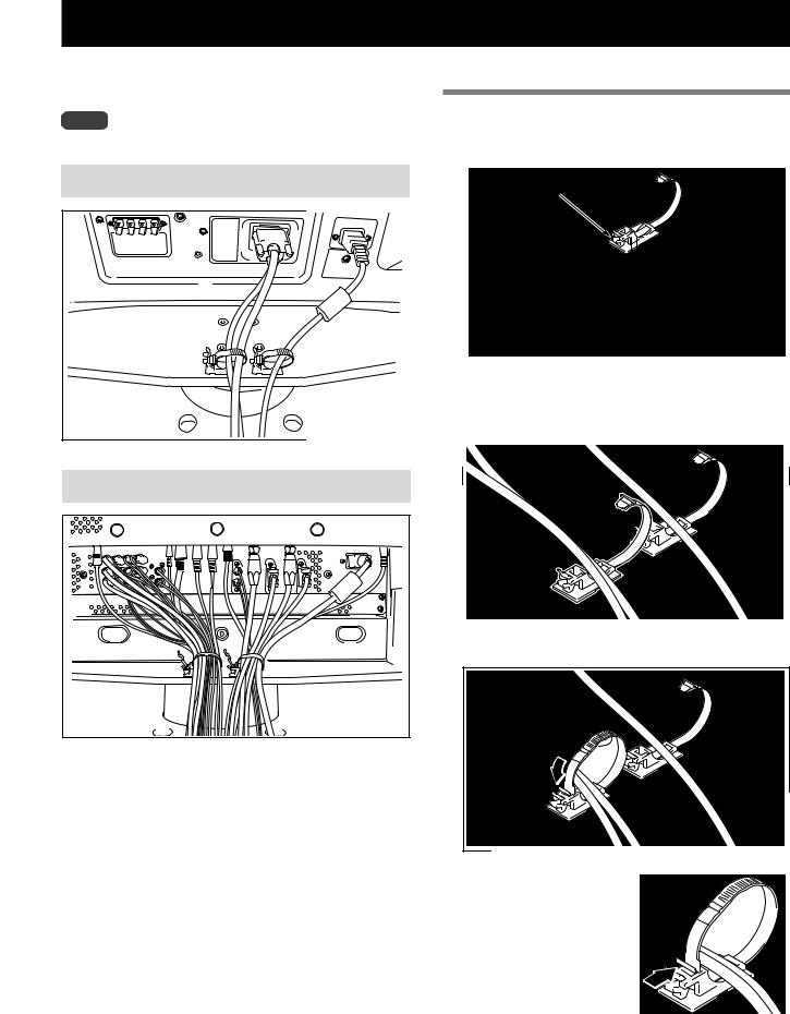
Preparing the Cables
Use the enclosed cable binders to bind the cables.
Note
Be very careful not to apply force to the bases of the cables.
When installing the PDP-S38 or PDP-S37 speakers
When installing the PDP-S39 speaker
Using the cable binders
1Insert the cable binder through the hole on the top of the rotating platform of the stand.
Cable binder
2Gathering cables and placing them on the cable binder.
3 Locking the cable binder.
Removing a cable binder
The lock is released by pushing the part indicated by the arrow in the figure.
18
En
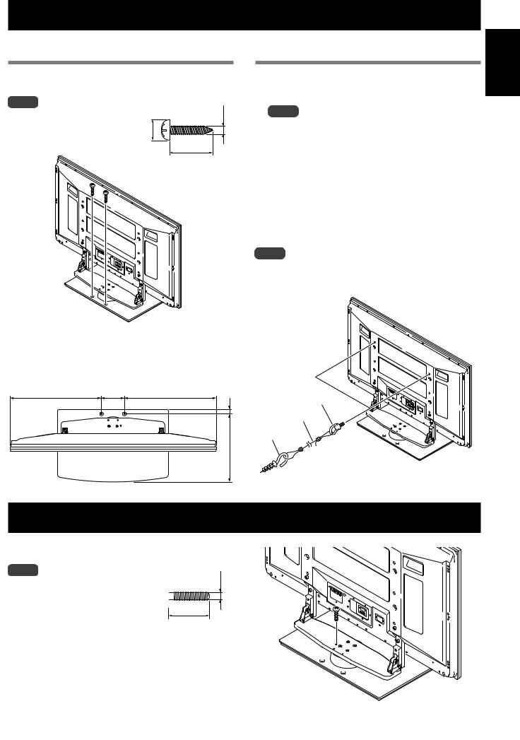
Preventing Equipment from Falling Over
After installing the stand, be sure to take special care to ensure that the Plasma Display will not fall over.
Stabilizing on table or floor
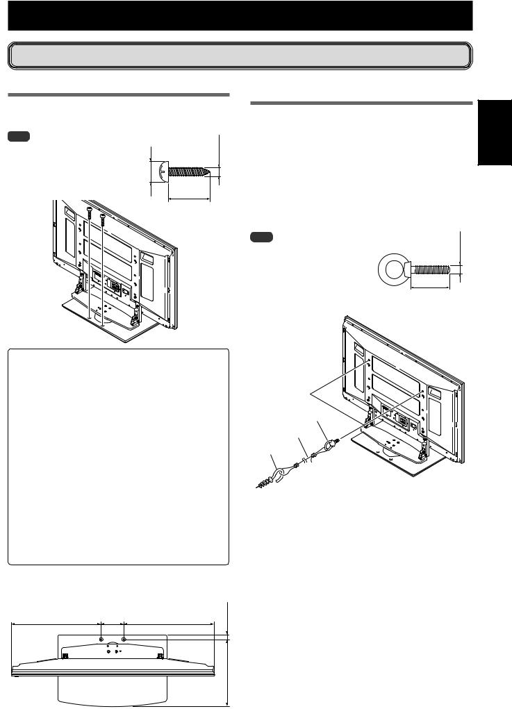
Stabilize the equipment as shown in the diagram using screws that are available on the market.
Note |
mm15to |
5/8toinch) |
6 mm (1/4 inch) |
mm (1/4 inch) and that are at least |
|||
To stabilize the Plasma Display on |
|
|
|
a table or on the floor, use screws |
|
|
|
that have a nominal diameter of 6 |
|
|
|
20 mm (13/16 inch) long. |
9 |
(3/8 |
Min. 20 mm |
|
|
||
|
|
(13/16 inch) |
|
|
|
|
Using a wall for stabilization
(43 inch display model in the figure)
1 |
Attaching falling prevention bolts to the |
English |
2 |
Plasma Display. |
|
Using strong cords or chains to stabilize it |
||
|
appropriately and firmly to a wall, pillar, or |
|
|
other sturdy element. |
|
|
Perform this work in the same way on the left and |
|
|
right sides. |
|
|
The length of the cords or chains used must be long |
|
|
enough to allow the stand to rotate freely. |
|
Note |
8mm inch)(3/8 |
|
|
||
Use falling prevention bolts, |
|
|
ropes, chains, and fittings that |
|
|
are available on the market. |
|
|
Recommended bolts: |
12 to 15mm |
|
Nominal diameter 8 mm (3/8 inch) |
||
(1/2 to 5/8 inch) |
||
Length 12 to 15 mm (1/2 to 5/8 inch) |
||
|
 Caution
•A table or an area of the floor with adequate strength should always be used to support the Plasma Display. Failure to do so could result in personal injury and physical damage.
•When installing the Plasma Display, please take the necessary safety measures to prevent it from falling or overturning in case of emergencies, such as earthquakes, or of accidents.
•If you do not take these precautions, the Plasma Display could fall down and cause injury.
•The screws, hooks, chains and other fittings that you use to secure the Plasma Display to prevent it from overturning will vary according to the composition and thickness of the surface to which it will be attached.
•Select the appropriate screws, hooks, chains and other fittings after first inspecting the surface carefully to determine its thickness and composition and after consulting a professional installer if necessary.
Position of table/floor screws: Without speakers
Unit: mm (inch)
522 (20-9/16)*
478 (18-27/32)**
120 |
522 |
(20-9/16)* |
(31/32) |
(4-23/32) |
478 |
(18-27/32)** |
|
|
|
|
24 |
|
|
|
356 (14-1/16) |
*: 50 inch display model
**: 43 inch display model
1 Falling prevention bolts
2 Cord or chain
Fitting
19
En
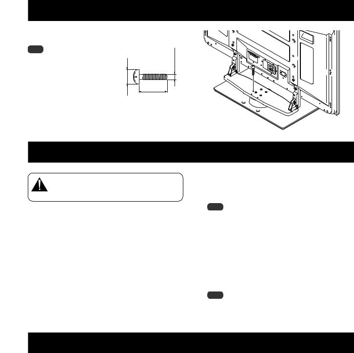
Fixing the rotation to the front
Stabilize the equipment as shown in the diagram using screws that are available on the market.
Note
Use a screw that has a nominal diameter of 4 mm (3/16 inch) and length from 20 to 30 mm (13/16 to 1-3/16 inch) to fix the rotation to the front.
7 to 12 mm (5/16 to 1/2 inch)
4 mm (3/16 inch)
20 to 30 mm (13/16 to 1-3/16 inch)
Detaching the Plasma Display from the Stand
To remove the Plasma Display from the stand, be sure to always follow the procedure described below to
Caution prevent accidents.
1First, confirm that the forward/backward inclination anchor bolt is securely tightened.
2First clear a space on a flat floor etc. where you can lay the Plasma Display flat, then lay a sheet to protect it from scratches or other damage.
3 Remove the speakers.
Specifications
4Referring to steps 2 and 3 in “Attaching the Plasma Display” (Page 15.), remove the installation screws (4 screws).
Note
Do not remove the screws (M8 x 16mm: silver) by procedure 2 in Page 14. The support columns might slip out of place and fall over.
5Holding the Plasma Display by its handles and from the bottom, lift the display vertically.
6Place the Plasma Display slowly onto the sheet laid out in step 2 with its screen facing downwards.
Note
When reattaching the Plasma Display to the stand, be certain that the left/right support columns are set at the same angle.
External dimensions |
577 (W) x 249.5 (H) x 380 (D) mm (22-23/32 (W) x 9-27/32 (H) x 14-31/32 (D) in.) |
|
[When using the support columns S] |
Weight |
10.5 kg (23.2 lbs) |
• The above specifications and exterior may be modified without prior notice to improve the product.
20
En
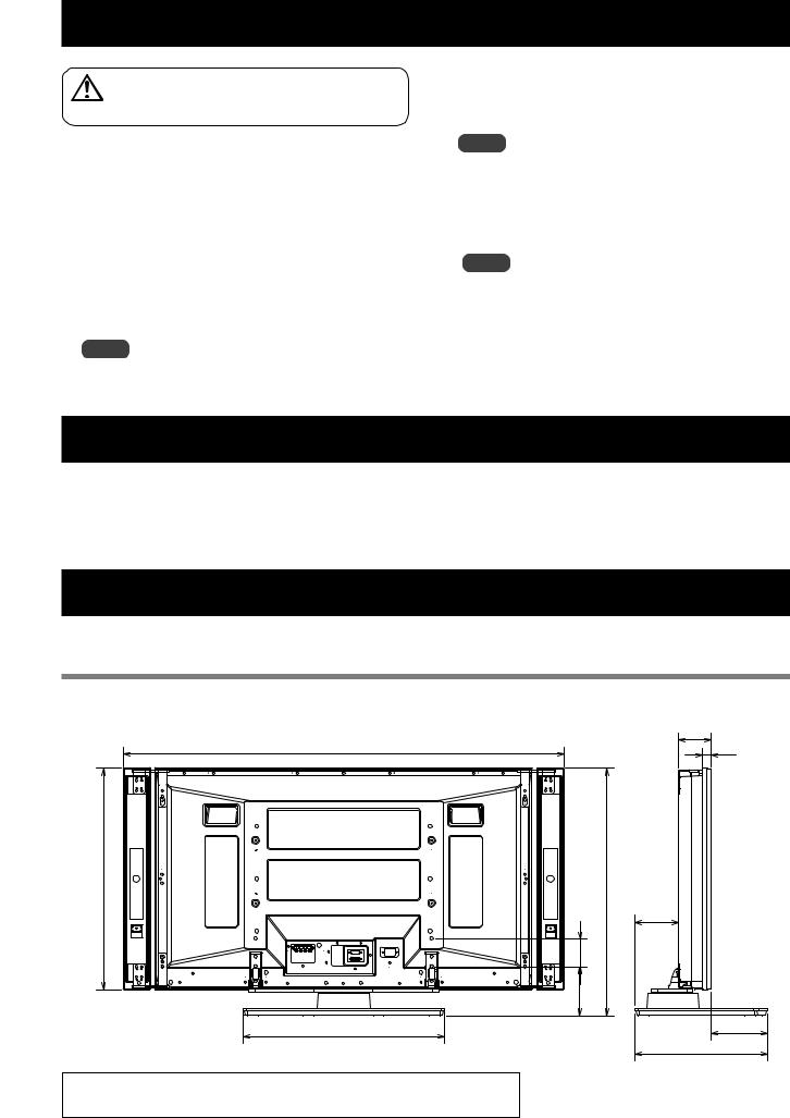
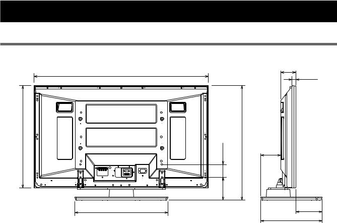
Dimensions Diagram
Unit: mm (inch)
When installing the PDP-S38 or the PDP-S37 speakers
1407 (55-13/32) [50 inch display model] *1 1379 (54-5/16) [50 inch display model] *2 1259 (49-19/32) [43 inch display model] *1 1231 (48-15/32) [43 inch display model] *2
717(28-1/4) [50 inch display model] (24632-29/32) [43 inch display model] |
140 |
17/32)- |
(31*791-5/32) [50 inch display model] (27*706-13/16) [43 inch display model] |
|
80 |
5/32) - |
|
|
|
(3 |
|
|
|
(5 |
|
577(22-23/32)
*When using the support columns L, the height is 853 (33-19/32) [50 inch display model] / 768 (30-1/4) [43 inch display model].
*1 Air installation: Attached with a space of approximately 15 mm between the speakers and the display. *2 Flush installation: Attached with the speakers in close contact with the display.
92 |
|
English |
|
(3-5/8) |
23 |
||
|
|||
|
|
||
|
(29/32) |
|
125.1 (4-15/16)
162.9 (6-7/16)
380 (14-31/32)
When installing the PDP-S39 speaker
1076 (42-3/8)
716 (28-7/32) |
80 |
(3-5/32) |
768 (30-1/4) |
|
202 |
-17/32) |
|
|
|
(5 |
|
|
577 (22-23/32) |
|
|
92
(3-5/8)
23
(29/32)
125.1 (4-15/16)
162.9 (6-7/16)
380 (14-31/32)
21
En
Dimensions Diagram
Without speakers
1224 (48-7/32) [50 inch display model]
1076 (42-3/8) [43 inch display model]
717 (28-1/4) [50 inch display model] 632 (24-29/32) [43 inch display model] |
140 80 -17/32) (3-5/32) |
*791 (31-5/32) [50 inch display model] *706 (27-13/16) [43 inch display model] |
|
(5 |
|
|
577 (22-23/32) |
|
92
(3-5/8)
23
(29/32)
125.1 (4-15/16)
162.9 (6-7/16)
380 (14-31/32)
* When using the support columns L, the height is 853 (33-19/32) [50 inch display model] / 768 (30-1/4) [43 inch display model].
Published by Pioneer Corporation.
Copyright © 2005 Pioneer Corporation.
All rights reserved.
22
En
Nous vous remercions d’avoir choisi un produit Pioneer. Veuillez lire attentivement ce mode d’emploi pour savoir comment utiliser correctement et en toute sécurité votre support. Nous vous conseillons de conserver soigneusement ce mode d’emploi à proximité et dans un endroit sûr afin de pouvoir vous y référer le cas échéant.
AVIS IMPORTANT – VEUILLEZ REPORTER CI-DESSOUS LES NUMEROS DE MODELE ET DE SERIE DE L’EQUIPEMENT.
CES NUMEROS APPARAISSENT A L’ARRIERE.
Nº MODELE :
Nº SERIE :
VEUILLEZ CONSERVER CES NUMEROS EN VUE DE FUTURES UTILISATIONS.
Installation
¶En cas de difficultés, veuillez consulter votre revendeur.
¶Pioneer ne saura être tenu responsable d’aucun dommage résultant d’une installation ou d’une utilisation incorrecte de ce produit, de sa modification ou encore de catastrophes naturelles.
Table des matières |
|
Attention .......................................................................... |
23 |
Vérification des pièces contenues dans le carton |
|
d’emballage ..................................................................... |
24 |
Tableau des colonnes de support utilisées / non |
|
utilisées ............................................................................ |
24 |
Assemblage du support ................................................. |
25 |
Installation et fixation de l’écran à plasma................... |
26 |
Mécanisme d’ajustement de l’angle d’inclinaison en |
|
avant et en arrière ........................................................... |
27 |
Installation du produit sur une étagère, etc. ................ |
28 |
Préparation des câbles ................................................... |
29 |
Prévenir le basculement et la chute de l’équipement ... |
30 |
Fixation de la rotation à l’avant ..................................... |
31 |
Démontage de l’écran à plasma du support ................ |
31 |
Spécificités....................................................................... |
31 |
Schéma indiquant les dimensions ................................ |
32 |
ATTENTION |
|
Ce symbole indique un danger ou une pratique |
|
dangereuse susceptible de provoquer des dommages corporels ou matériels.
Attention
Ce produit est un support conçu exclusivement pour les écrans à |
|
||||||||||||||||||||||||||||||||||||
plasma Pioneer (PDP-5060HD / PDP-4360HD / PDP-506XDE / |
|
||||||||||||||||||||||||||||||||||||
PDP-436XDE / PDP-506FDE / PDP-436FDE / PDP-506HDG / |
|
||||||||||||||||||||||||||||||||||||
PDP-436HDG). |
|
||||||||||||||||||||||||||||||||||||
L’utilisation de ce produit avec un autre modèle peut être à |
|
||||||||||||||||||||||||||||||||||||
l’origine d’un manque de stabilité pouvant entraîner une blessure. |
|
||||||||||||||||||||||||||||||||||||
English |
|||||||||||||||||||||||||||||||||||||
Pour de plus amples informations, veuillez contacter le magasin |
|||||||||||||||||||||||||||||||||||||
|
|||||||||||||||||||||||||||||||||||||
où vous avez acheté votre écran. |
|
||||||||||||||||||||||||||||||||||||
|
|
|
|
|
|
|
|
|
|
|
|
|
|
|
|
|
|
|
|
|
|
|
|
|
|
|
|
|
|
|
|
|
|
|
|
|
|
N’installez pas le produit d’une manière autre que celle qui est |
|
||||||||||||||||||||||||||||||||||||
spécifiée ni le modifier. En outre, n’utilisez pas ce support pour un |
|
||||||||||||||||||||||||||||||||||||
écran à plasma autre que ceux pour lesquels il a été conçu et ne le |
|
||||||||||||||||||||||||||||||||||||
|
|||||||||||||||||||||||||||||||||||||
modifiez pas ou ne l’utilisez pas à des fins autres que celles pour |
Français |
||||||||||||||||||||||||||||||||||||
lesquelles il a été conçu. |
|||||||||||||||||||||||||||||||||||||
|
|||||||||||||||||||||||||||||||||||||
|
|
|
|
|
|
|
|
|
|
|
|
|
|
|
|
|
|
|
|
|
|
|
|
|
|
|
|
|
|
|
|
|
|
|
|
|
|
Une installation incorrecte est extrêmement dangereuse car elle |
|
||||||||||||||||||||||||||||||||||||
peut provoquer la chute du support ou un autre accident. |
|
||||||||||||||||||||||||||||||||||||
|
|
|
|
|
|
|
|
|
|
|
|
|
|
|
|
|
|
|
|
|
|
|
|
|
|
|
|
|
|
|
|
|
|
|
|
|
|
|
|
|
|
|
|
|
|
|
|
|
|
|
|
|
|
|
|
|
|
|
|
|
|
|
|
|
|
|
|
|
|
|
|
|
|
|
|
Lieu d’installation
•Sélectionnez un emplacement assez solide pour supporter le poids du support et de l’écran.
•Assurez-vous de placer le produit à un emplacement stable et plat.
•N’installez pas le support à l’extérieur, à proximité d’une source thermale ou sur une plage.
•N’installez pas le support à un endroit où il pourrait être soumis à des chocs ou à des vibrations.
Montage et installation
•Montez le support en suivant les instructions et vissez solidement toutes les vis aux endroits prévus à cet effet. Des accidents ont été constatés (casse, chute du matériel, etc.) après l’installation de l’écran parce que le support n’avait pas été installé conformément aux instructions.
•Pour une bonne installation, l’écran doit toujours être installé par au moins deux personnes.
•Avant de procéder à l’installation, mettez l’écran ainsi que les équipements périphériques hors tension en coupant l’alimentation, puis retirer la prise du câble d’alimentation de la prise murale.
Ce produit pivote de 10° vers la gauche et la droite et s’incline de 2° environ en avant et en arrière.
Veillez à ne pas placer d’objets à l’intérieur du champ de rotation de telle sorte que durant l’utilisation habituelle ou la rotation du produit, rien ne dépasse de l’étagère ou de l’emplacement sur lequel il a été installé. Sans cela, des accidents pourraient survenir, entraînant la détérioration de l’appareil ou sa chute (Voir page 28). Lorsque vous ajustez l’angle vers l’avant et vers l’arrière, faites extrêmement attention à ne pas placer vos mains entre le bas de l’écran à plasma et le support (Voir page 27).
Il convient de prévenir les accidents causés par la chute du produit, en cas de tremblement de terre ou autres, en prenant des mesures fiables pour éviter toute chute (Voir page 30).
23
Fr
Vérification des pièces contenues dans le carton d’emballage
Cette vérification vous permettra de vous assurer que vous possédez bien toutes les pièces nécessaires avant de procéder au montage et
àl’installation du support.
Support de couverture de table x 1 unité
Colonnes de support S x 2 unités [Colonnes courtes]
*Ne peuvent pas être utilisé(e)s pour l’installation du PDP-S39.
Colonnes de support L x 2 unités [Colonnes longues]
Serre-câbles x 2 unités
Vis d’installation 1 (M8 x 16 mm : argentée) x 4 unités [Utilisées pour fixer les colonnes de support et le support de couverture de table]
Vis d’installation 2 |
Mode d’emploi |
(M8 x 30 mm : argentée) x 2 unités |
(ce document) x 1 exemplaire |
Table top stand
Support de couverture de table
Tischständer
Supporto di tavolo
Tafelbladstaander
Soporte de mesa
PDK-TS12
Vis d’installation 3
(M8 x 40 mm : noir) x 2 unités
Operating instructions
Mode d’emploi
Bedienungsanleitung
Istruzioni per l’uso
Gebruiksaanwijzing
Manual de instrucciones
Clé hexagonale (à six pans) x 1 unité |
Clé hexagonale x 1 unité |
Vis d’installation 4 |
(Taille en diagonale : 6 mm) |
(10 mm) |
(M8 x 60 mm : argentée) x 2 unités |
|
|
*Peuvent être utilisé(e)s pour l’installation du PDP-436SX. |
Tableau des colonnes de support utilisées / non utilisées
Les différentes colonnes de ce support à utiliser varient en fonction des haut-parleurs et de l’écran à plasma que vous avez achetés. Veuillez sélectionner les colonnes de support que vous allez utiliser en vous reportant au tableau suivant.
|
|
|
|
|
|
|
|
|
Lieu d’installation |
Produit acheté |
Colonnes de support S |
Colonnes de support L |
|||
|
Ecran à plasma |
|
Haut-parleur |
(colonnes courtes) |
|
(colonnes longues) |
|
|
|
|
|
||||
|
|
PDP-506HD / PDP-436HD |
Utilisation recommandée |
|
*Peuvent être utilisées |
||
|
Japon |
|
|
|
|
|
|
|
PDP-436SX |
|
(Ecran à plasma et |
Ne peuvent être utilisées |
|
A utiliser |
|
|
|
|
haut-parleurs intégrés) |
|
|||
|
|
|
|
|
|
|
|
|
|
|
|
PDP-S38 / PDP-S37 |
Utilisation recommandée |
|
*Peuvent être utilisées |
|
Amérique du Nord |
|
|
|
|
|
|
|
PDP-506PU / PDP-436PU |
|
PDP-S39 |
Ne peuvent être utilisées |
|
A utiliser |
|
|
|
|
|
|
|
|
|
|
|
|
|
Sans haut-parleurs |
Utilisation recommandée |
|
*Peuvent être utilisées |
|
|
|
|
|
|
|
|
|
|
|
|
PDP-S38 / PDP-S37 |
Utilisation recommandée |
|
*Peuvent être utilisées |
|
Europe |
PDP-506PE / PDP-436PE |
|
PDP-S39 |
Ne peuvent être utilisées |
|
A utiliser |
|
|
|
|
|
|
|
|
|
|
|
|
Sans haut-parleurs |
Utilisation recommandée |
|
*Peuvent être utilisées |
|
|
|
|
|
|
|
|
|
|
|
|
PDP-S38 / PDP-S37 |
Utilisation recommandée |
|
*Peuvent être utilisées |
|
Autres pays |
PDP-506PG / PDP-436PG |
|
PDP-S39 |
Ne peuvent être utilisées |
|
A utiliser |
|
|
|
|
Sans haut-parleurs |
Utilisation recommandée |
|
*Peuvent être utilisées |
24 |
* : Peuvent être utilisées lorsque l’écran est placé en hauteur. |
|
|
|
|
||
Fr
Assemblage du support
Remarques
Pour monter le support, travaillez toujours sur une surface plane.
Introduisez les vis à la verticale et ne les serrez pas plus que nécessaire.
Procédure de montage
1Sélectionnez les colonnes de support à fixer (voir “Tableau des colonnes de support utilisées / non utilisées” page 24).
Sélectionnez les colonnes de support en fonction de l’emplacement des haut-parleurs que vous avez achetés et d’après les indications ci-dessous (un seul des deux jeux de colonnes doit être utilisé).
Si vous avez acheté des haut-parleurs PDP-S38 et le PDP-S37.
[Colonnes de support utilisées : colonnes de support S (Colonnes courtes)]
Colonnes de support utilisées : colonnes de support S (Colonnes courtes)
Si vous avez acheté des haut-parleur PDP-S39.
[Colonnes de support utilisées : colonnes de support L (Colonnes longues)]
Colonnes de support S (Colonnes courtes) ne peuvent pas être utilisées.
Colonnes de support utilisées : colonnes de support L (Colonnes longues)
2Fixez les colonnes sur le support à l’aide des vis d’installation 1 (2 sur le côté gauche et 2 sur le côté droit).
A l’aide de la clé hexagonale fournie, vissez légèrement les vis en commençant par celle du haut.
Illustration lorsque l’on utilise les colonnes de support S.
Les orifices les plus larges se trouvent à l’avant.
Français
Vis d’installation 1 (M8 x 16 mm : argentée)
3Vissez à fond les vis d’installation (2 sur le côté gauche et 2 sur le côté droit).
Vissez à fond les vis d’installation.
Remarques
Veillez à bien ranger les colonnes de support non utilisées, la clé hexagonale, la clé C et le mode d’emploi au même endroit.
25
Fr
Installation et fixation de l’écran à plasma
Le poids d’un écran à plasma 50 pouces (seul sans les haut-parleurs) est de 32 kg environ et celui d’un modèle
43 pouces (seul sans les haut-parleurs) de 26 kg environ. Attention Leur largeur étant limitée, ils ne sont pas stables. Par
conséquent, ils doivent toujours être installés par deux personnes à la fois.
Remarques
Montez toujours l’écran à plasma sur une surface plane et stable.
Introduisez les vis à la verticale et ne les serrez pas plus que nécessaire.
Veillez à bien installer les colonnes en fonction de l’emplacement des haut-parleurs que vous avez achetées et en suivant la marche à suivre décrite dans le chapitre Montage du support.
Méthode de fixation
1 Installation de l’écran à plasma sur le support.
Mettez les colonnes de soutien en place au bas de l’écran à plasma comme indiqué par les flèches, puis insérez-les lentement à la verticale. Veillez à ne pas insérer les colonnes ailleurs que dans les fentes prévues à cet effet. Cela risquerait d’endommager l’écran, ses ports ou encore le support.
Alignez les colonnes du support sur la partie inférieure de l’écran comme indiqué sur le schéma ci-joint.
2Fixez solidement l’écran à plasma avec les vis d’installation 2.
Vissez solidement celles-ci au moyen de la clé hexagonale fournie avec le support.
Illustration lorsque l’on utilise les colonnes de support L.
Vis d’installation 2  (M8 x 30 mm : argentée)
3Fixez solidement l’écran à plasma avec les vis d’installation 3.
Fixez l’écran à plasma aux endroits indiqués par les flèches à l’aide de la vis hexagonale fournie.
Vis d’installation 3 |
(M8 x 40 mm : noir) |
4 Mise en place des haut-parleurs.
Pour la méthode d’installation, reportez-vous au mode d’emploi des haut-parleurs.
Illustration lorsque l’on utilise les colonnes de support S.
Vis d’installation 2
 (M8 x 30 mm : argentée)
26
Fr
Mécanisme d’ajustement de l’angle d’inclinaison en avant et en arrière
Lors de cette étape, vous pouvez choisir de régler l’angle d’inclinaison de l’écran à plasma de 2° environ en avant ou en arrière.
Remarques
Veuillez ajuster l’angle uniquement après avoir fixé l’écran à plasma.
Assurez-vous de l’installer sur une table plane ou toute autre surface plane.
Assurez-vous de tenir le haut de l’écran à plasma entre vos mains lorsque vous ajustez l’angle.
Procédure d’ajustement
1Desserrez les boulons d’ancrage servant à régler l’inclinaison en avant et en arrière à l’aide de la clé hexagonale fournie
(2 emplacements à gauche et à droite).
En vous assurant de tenir le haut de l’écran à plasma entre vos mains, desserrez les boulons d’ancrage servant à régler l’inclinaison en avant et en arrière, sur le côté gauche et sur le côté droit, en les tournant vers le haut à l’aide de la clé hexagonale fournie.
*Le schéma illustre le modèle d’écran de 43 pouces.
Boulons d’ancrage servant à régler l’inclinaison en avant et en arrière
Desserrement
3Serrez les boulons d’ancrage servant à régler l’inclinaison en avant et en arrière
(2 emplacements à gauche et à droite).
Serrez fermement les boulons d’ancrage servant à régler l’inclinaison en avant et en arrière, sur le côté gauche et sur le côté droit, en les tournant vers le bas à l’aide de la clé hexagonale fournie. Assurez-vous de tenir le haut de l’écran à plasma entre vos mains jusqu’à ce que les boulons soient complètement serrés.
Boulons d’ancrage servant à régler l’inclinaison en avant et en arrière
Resserrement
4Vérifiez une fois de plus que les boulons d’ancrage servant à régler l’inclinaison en avant et en arrière sont complètement serrés.
2 Choisissez l’angle que vous préférez.
Choisissez l’angle que vous préférez en manipulant doucement l’écran à plasma.
Français
2˚
2˚
Remarque
Lorsque vous ajustez l’angle, faites bien attention à ne pas placer vos mains à l’endroit indiqué par un cercle sur le schéma.
27
Fr
 Loading...