


Speaker System Enceinte acoustique Lautsprechersystem Sistema di diffusori Luidsprekersysteem Sistema de altavoces
PDP-S41
Operating Instructions Mode d’emploi Bedienungsanleitung Istruzioni per l’uso Gebruiksaanwijzing Manual de instrucciones
English
Thank you for buying this Pioneer product.
Please read through these operating instructions before using your speaker system so you will know how to make the most of its performance. After you have finished reading the instructions, put them away in a safe place for future reference.
WARNING: Handling the cords associated with accessories sold with the product will expose you to chemicals listed on proposition 65 known to the State of California and other governmental entities to cause cancer and birth defect or other reproductive harm.
Wash hands after handling
CAUTION
About compatibility
This product is designed exclusively for use with the Pioneer Plasma Display. For more information on compatibility, please consult with your nearest Pioneer authorized dealer or service center.
About installation and setting
•If you want to move the Plasma Display unit, make sure that you remove the speaker first. In addition, do not move the display holding on to the mounting fittings. This can result in injury or damage to the unit.
•This speaker is wide, and may become unstable when installed by a one person alone. This may result in injury or product damage. Therefore, at least two people must assemble and install them.
•When installing the speaker, do not use any screws other than those supplied, otherwise the speaker may come off from the main unit and fall over.
•When installing the speaker, tighten the screws firmly.
•Please handle the speaker with sufficient care, as the grille net and the cabinet can become damaged or broken when they are subjected to strong external impacts.
•Placing a CRT computer screen or CRT monitor near to the speaker may result in interference or color distortion. If this happens, distance the monitor from the speaker.
About the input
•In order to prevent damage to the speaker system resulting from input overload, please observe the following precautions:
•Do not use the speaker with anything other than the specified Pioneer Plasma Display. Doing so may result in damage or fire.
•Be sure to turn the connected devices off and remove the power cord from the wall outlet beforehand when changing the connection or installation method.
•When using a tone control function to greatly emphasize treble sounds, do not use excessive amplifier volume.
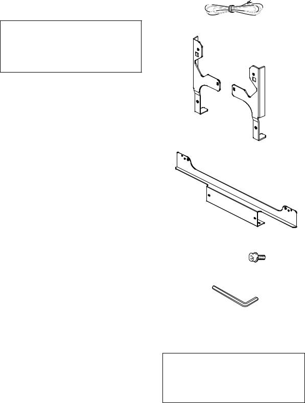
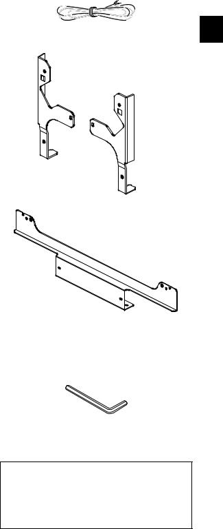
CHECKING THE ACCESSORIES
•Speaker Cable × 2
•Speaker Mounting Fittings
Bracket, for Right and Left Sides
Bracket for Center
• Speaker Mounting Screw
(M5 × 10 mm : Black) × 12
•Hexagonal wrench
(Opposite side 4 mm for M5 use) x 1
•Operating Instructions
Installation
•Consult your dealer if you encounter any difficulties with this installation.
•Pioneer is not liable for any damage resulting from improper installation, improper use, modification, or natural disasters.
2
English
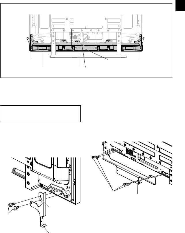
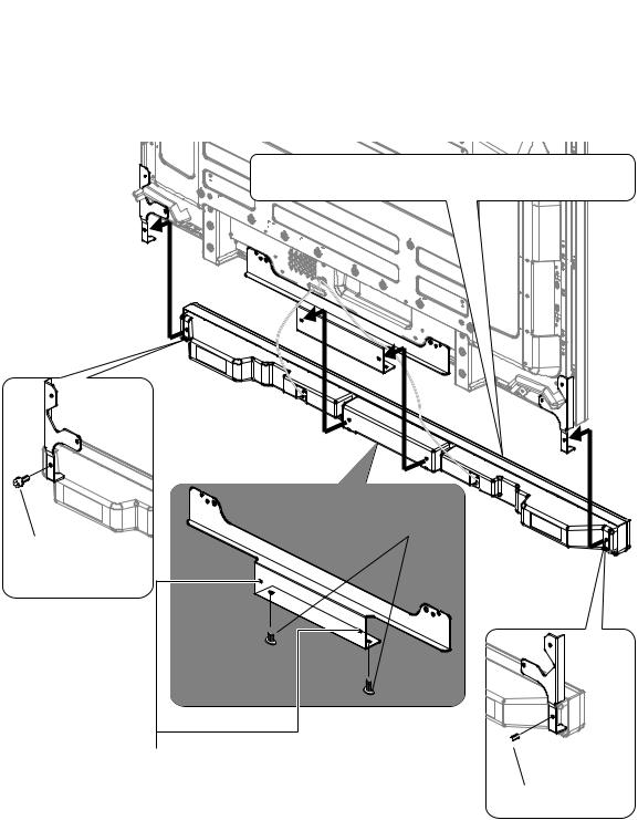
Plasma Display with the speaker installed
Speaker mounting  screw (M5 x 10 mm)
Speaker |
|
|
|
mounting |
|
|
|
screw |
|
|
Speaker |
(M5 x 10 mm) |
|
|
|
|
|
|
mounting screw |
|
|
|
(M5 x 10 mm) |
Speaker mounting fitting |
|
Speaker mounting |
Speaker mounting |
(right side) |
|
fitting (center) |
fitting (left side) |
Speaker |
Speaker cable |
Bead Band |
|
|
|
(Accessories of the Plasma Display) |
|
English
INSTALLATION ON THE PLASMA DISPLAY
Perform installation according to the following steps 1 to 4.
 NOTE:
NOTE:
Before attaching the speaker, please attach the table top stand to the Plasma Display unit.
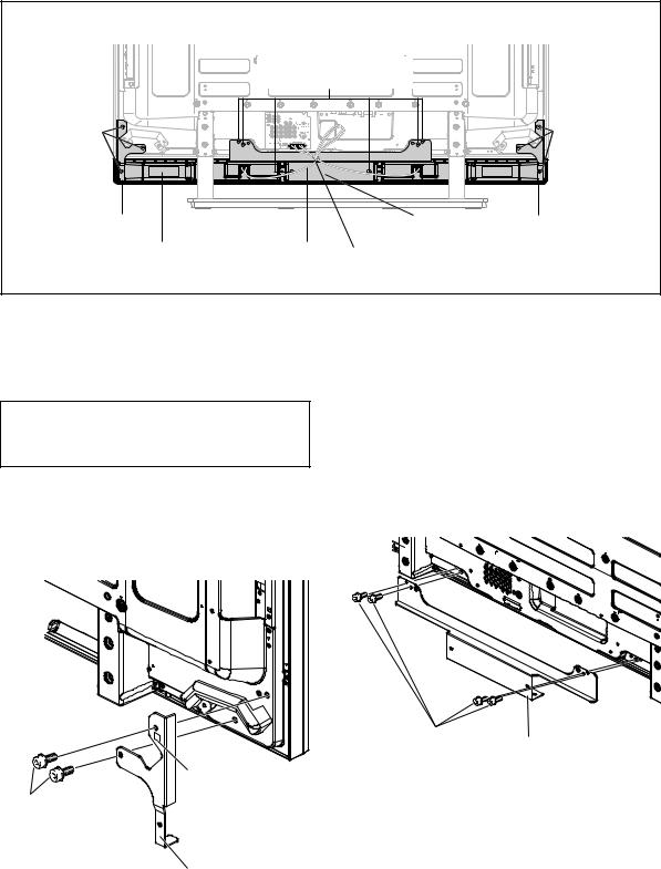
1. Attach the speaker mounting fittings to the rear of the Plasma Display.
•Attach the fittings for right and left sides to the bottom right and left on the rear panel of the Plasma Display using the supplied screws.
•Tighten the two screws in the order 1 followed by 2.
1
|
Label “L” is |
|
2 |
affixed to the left |
|
Speaker mounting |
side fitting. |
|
(Similarly, label |
||
screw (M5 x 10 mm) |
||
“R” is |
||
|
||
|
affixed to the |
|
|
right side fitting.) |
|
|
Speaker mounting fitting for the |
|
|
left side |
|
|
(the fitting method is the same |
|
|
as the fitting for the right side) |
2. Attach the center fitting to the lower center on the rear panel of the Plasma Display.
•Attach the center fitting to the lower center on the rear panel of the Plasma Display using the four supplied screws.
•Tighten the four screws in the order 1, 2, 3, 4as shown in the drawing.
•When fitting the screws, place screws 1 and 2 through the holes in the center fitting, and align screws 3 and 4 with the cutaway slots in the center fitting.
4
2
1
3
Speaker mounting
screw (M5 x 10 mm) Speaker mounting fitting for center
 NOTE:
NOTE:
•See page 6 for speaker mounting procedures when using the hung on wall unit.
3
English
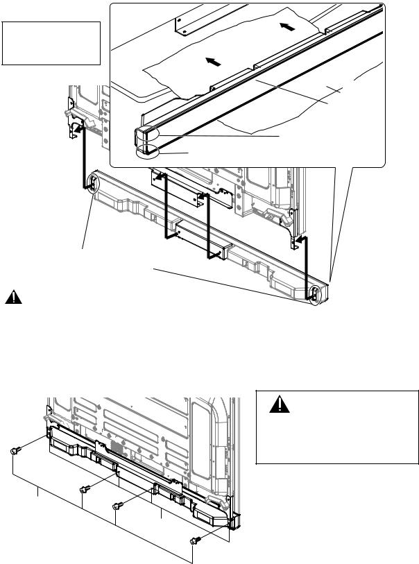
3. Fit the speaker to the mounting fittings in the correct direction.
• Be sure not to mount the speaker upside down.
For illustrative purposes, the table top stand is not presented here.
Protective |
wrapping |
Front side of the speaker
The upper side of the speaker does not have a round corner.
The bottom side of the sp
 eaker has a round corner when viewed from the front side of the Plasma Display.
Insert the speaker mounting fittings into the grooves at the rear of the speaker.
Caution
•To avoid any damage to the speaker and/or table top stand from striking against each other, fit the speaker to the mounting fittings while confirming their locations. As you may easily strike the stand, use the protective wrapping in which the speaker was wrapped between the speaker and stand.
•When the speaker mounting fittings do not fit the grooves at the rear of the speaker, adjust the speaker mounting fittings angle.
4. Fix the speaker mounting fittings and the speaker with the supplied screws.
•Fix the center part of the speaker first with the supplied screws, then fix the right and left sides alike.
•Tighten the four screws in the order 1, 2, 3, 4 as shown in the drawing.
4
|
2 |
Speaker |
1 |
mounting screw |
|
(M5 x 10 mm) |
|
Screw hole
3 
CAUTION
If you want to move the Plasma Display unit, make sure that you remove the speaker first. In addition, do not move the display holding on to the mounting fittings. This can result in injury or damage to the unit.
The screw hole at the bottom surface of the speaker mounting fitting is used when the Plasma Display is installed on the wall. It is not used when installed with the stand.
 NOTE:
NOTE:
If after attaching the speaker its position needs to be adjusted horizontally or vertically, first loosen the speaker mounting screws, reposition and then tighten the screws again at the appropriate position.
4
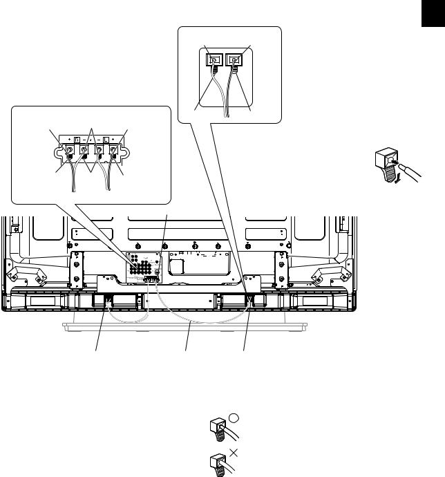
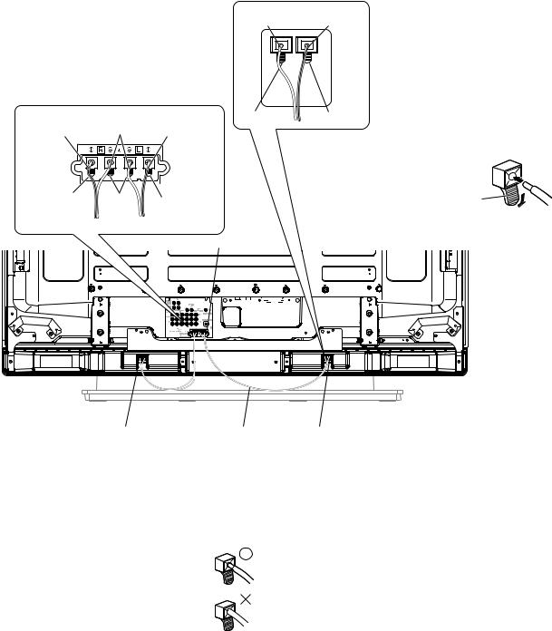
5.Connect the supplied speaker cables to the back of Plasma
Display.
•Connect the cables correctly with respect to the polarity of the Plasma Display and the speaker terminals, that is, cable to terminals andcable to terminals. To do so, connect the cable with the gray line to the terminals and the white cable to the terminals.
Gray line |
White |
Gray line |
Red |
Black |
Red |
|
|
White |
Gray line |
Black Red
English
6.Connect the other end of the speaker cables
to the speaker.
•Connect the cables correctly with respect to the polarity of the Plasma Display and the speaker terminals, that is, cable to terminals andcable to terminals. To do so, connect the cable with the gray line to the terminals and the white cable to the terminals.
• Press the lever and insert the end of the
cable.
• When you release the lever, it clamps onto
the speaker cable.
Lever 
Speaker terminal
English
|
|
|
|
|
|
|
|
|
|
|
|
|
|
|
|
|
|
|
|
|
|
|
|
|
|
|
|
|
|
|
|
|
|
|
|
|
|
|
|
|
|
|
|
|
|
|
|
|
|
|
|
|
|
|
|
|
|
|
|
|
|
|
|
|
|
|
|
|
|
|
|
|
|
|
|
|
|
|
|
|
|
|
|
|
|
|
|
|
|
|
|
|
|
|
|
|
|
|
|
|
|
|
|
|
|
|
|
|
|
|
|
|
|
|
|
|
|
|
|
|
|
|
|
|
|
|
|
|
|
|
|
|
|
|
|
|
|
|
|
|
|
|
|
|
|
|
|
|
|
|
|
|
|
|
|
|
|
|
|
|
|
|
|
|
|
|
|
|
|
|
|
|
|
|
|
|
|
|
|
|
|
|
|
Speaker terminal |
|
Speaker cable |
|
|
|
Speaker terminal |
|
|
||||||||||||||
 Caution
•Be sure to turn the connected devices off and remove the power cord from the wall outlet beforehand when changing the connection or installation method.
• If you insert the speaker cable too far so that the insulation is touching the speaker terminal, you may not get any sound. Please insert it with showing the copper wire.
• Check if the end of the speaker cables are securely connected to the terminals by slightly tugging on the cable after making connections. Loose connections may result in sound dropouts or noise.
•If there is a short in the and cables caused by an exposed lead wire, excessive load may be applied to the Plasma Display, resulting in interrupted operation or malfunction.
•Incorrect connections of the speaker cable to the right or left of the Plasma Display terminals with respect to the polarity may result in insufficient stereo sound effects, delivering poor bass sounds or unstable sound image.
•Bundle the code without pulling the cord.
5
English
When using the hung on wall unit:
First install the Plasma Display on the wall with only the speaker mounting fittings and speaker cable attached to the display, and then attach the speaker. (See page 3)
To facilitate attachment of wiring, it is recommended to complete the wiring on the sides of the Plasma Display before mounting speaker to the display.
 Caution
Be careful about the speaker mounting fittings when installing or connecting. This may result in injury.
3.Connect the supplied speaker cables to the back of the Plasma Display.
4.Place the Plasma Display on the mounting fittings of the hung on wall unit.
• For details, refer to the instruction manual supplied with the hung on wall unit.
5. Connect the other end of the speaker cables to the speaker.

 6. Place the speaker on the speaker mounting
 fittings in the correct direction.
4
Speaker mounting screw
(M5 x 10 mm)
Speaker mounting screw (M5 x 10 mm)
2 
1
 3
3
When using the hung on wall unit, do not use these
holes.
Speaker mounting screw (M5 x 10 mm)
7. Tighten using the supplied screws (4 locations).
• Tighten the four screws in the order 1, 2, 3, 4 as shown in the drawing.
6
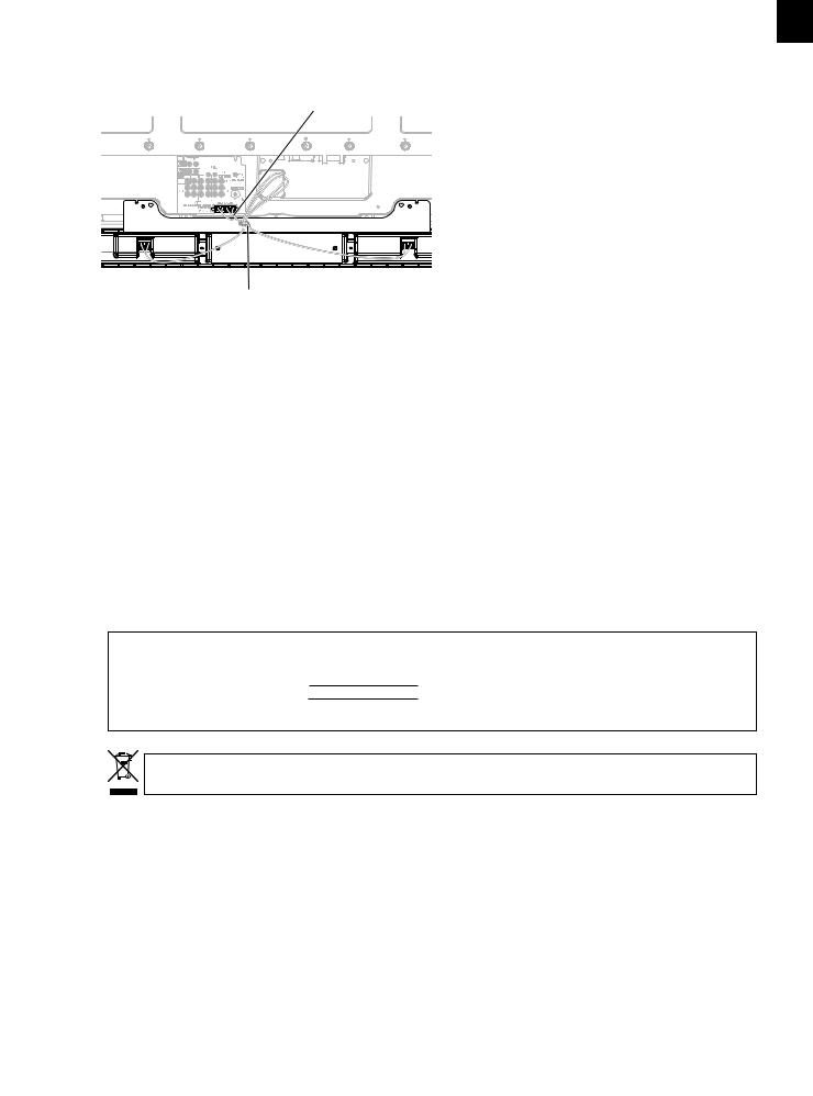
HOW TO ROUTE CABLES
Bead bands are included with the Plasma Display.
For tidying up your speaker cables, use the bead bands when needed.
Speaker cable
Rear of Display
Bead Band
CABINET MAINTENANCE
•Use a polishing cloth or dry cloth to wipe off dust and dirt.
•When the cabinet is very dirty, wipe with a soft cloth moistened with water-diluted cleanser; then wipe again with a dry cloth. Do not use furniture wax or cleaners. They may damage the surface of the cabinet.
•Never use thinner, benzine, insecticide sprays and other chemicals on or near the cabinets, since these will corrode the surfaces.
•When a chemical cloth is used, read the cautions for the chemical cloth carefully.
English
SPECIFICATIONS
Cabinet: Bass-reflex type
Used speaker (two-way system):
Woofer (for low tones) .......... |
4.8 cm × 13 cm cone type |
Tweeter (for high tones) ........... |
2.5 cm semidome type |
Nominal impedance ..................................................... |
8 Ω |
Frequency Range ................................ |
66 Hz to 30 000 Hz |
Sensitivity (1 m, 1 W) ............................................... |
80 dB |
Permissible input : |
|
Max. input .............................................................. |
13 W |
Rated input .............................................................. |
4 W |
Crossover frequency ................................................ |
3 kHz |
External Dimensions |
|
..................... |
1 470 mm (W) × 87 mm (H) × 115 mm (D) |
Weight ..................................................................... |
3.8 kg |
Accessory parts
............................................................ Speaker cable × 2
............................................................................. Bracket Right × 1 Left × 1 Center × 1
.............................................. Screw (M5 × 10 mm) × 12
..................................................... Hexagonal wrench x 1
.............................................. Operating Instructions × 1
NOTE:
Specifications and design subject to possible modification without notice, due to improvements.
English
IMPORTANT NOTICE – RECORD THE MODEL NUMBER AND SERIAL NUMBERS OF THIS EQUIPMENT BELOW. THE NUMBERS ARE ON THE REAR.
MODEL NO.
SERIAL NO.
KEEP THESE NUMBERS FOR FUTURE USE.
D1-4-2-6-2_En
If you want to dispose this product, do not mix it with general household waste. There is a separate collection system for used electronic products in accordance with legislation that requires proper treatment, recovery and recycling.
Private households in the 25 member states of the EU, in Switzerland and Norway may return their used electronic products free of charge to designated collection facilities or to a retailer (if you purchase a similar new one).
For countries not mentioned above, please contact your local authorities for the correct method of disposal.
By doing so you will ensure that your disposed product undergoes the necessary treatment, recovery and recycling and thus prevent potential negative effects on the environment and human health.
7

English
8
Merci pour votre achat de cet appareil Pioneer.
Veuillez lire attentivement la totalite de ce mode d’emploi avant d’utiliser vos enceintes acoustiques de façon à pouvoir en tirer le meilleur profit. Après lecture complète du livret d’instructions de fonctionnement, le ranger dans un endroit sûr afin de pouvoir vous y reporter facilement en cas de besoin lors de l’utilisation des l’enceintes acoustiques.
ATTENTION
À propos de la compatibilité
Ce produit est conçu exclusivement pour l’utilisation avec un Écran Plasma Pioneer. Pour de plus amples informations sur la compatibilité, veuillez vous adresser au distributeur ou au centre de service Pioneer agréé le plus proche.
À propos de l’installation et des réglages
•Si vous déplacez l’Écran Plasma, veillez à retirer d’abord les enceintes. De plus, ne déplacez pas l’écran en le tenant par ses ferrures de fixation, car vous pourriez vous blesser ou endommager l’appareil.
•Cette enceinte est large et elle risque d’être déstabilisée si elle est installée par une seule personne. Ce qui peut entraîner des blessures ou des dégâts à l’appareil. Par conséquent, il est conseillé d’agir à deux pour assembler et installer les éléments.
•À l’installation des enceintes, utilisez uniquement les vis fournies, car d’autres pourraient se détacher de l’unité principale et entraîner la chute des enceintes.
•A l’installation des enceintes, serrez les vis à fond.
•Manipuler les enceintes avec suffisamment de soin, car autrement, l’enjoliveur frontal et le coffret risqueraient d’être endommagés ou hors d’usage en les soumettant à des chocs externes exagérés.
•La présence d’un écran d’ordinateur ou d’un moniteur à tube cathodique près des enceintes peut provoquer des interférences et une distorsion des couleurs. Si c’est le cas, éloignez l’écran par rapport aux enceintes.
À propos de l’entrée des signaux
•Afin d’éviter d’endommager les enceintes acoustiques, suite à une surcharge à l’entrée, veuillez observer les précautions suivantes:
•N’utilisez jamais les enceintes avec un appareil autre que l’Écran Plasma Pioneer spécifié. Faute de quoi, des dégâts, voire un incendie pourraient en résulter.
•Prenez soin de mettre hors tension les appareils raccordés et de débrancher le cordon d’alimentation au niveau de la prise secteur avant de changer les connexions ou la méthode d’installation.
•Si vous utilisez une fonction de contrôle des tonalités pour accentuer fortement les aigus, n’élevez pas excessivement le volume sonore.
Français
VÉRIFICATION DES
ACCESSOIRES
•Câbles d’enceinte × 2
•Supports pour montage des enceintes
Support, pour côtés gauche et droit
Français
Support central
•Vis de montage d’enceintes
(M5 × 10 mm : Noires) × 12 
•Clé hexagonale
(Taille en diagonale 4 mm pour utilisation M5) x 1
•Mode d’emploi
Installation
•En cas de difficultés, veuillez consulter votre revendeur.
•Pioneer ne saurait être tenu responsable d’aucun dommage résultant d’une installation ou d’une utilisation incorrecte de ce produit, de sa modification ou encore de catastrophes naturelles.
9
Français
Écran Plasma doté de ses enceintes
Vis de montage d’enceintes (M5 x 10 mm)
Ferrure de montage d’enceintes (côté droit)
Vis de montage d’enceintes (M5 x 10 mm)
Ferrure de montage |
d’enceintes (centre) |
Enceintes |
Câble d’enceinte |
|
Collier à grains |
|
(Accessoire pour Écran Plasma) |
Vis de montage d’enceintes (M5 x 10 mm)
Ferrure de montage d’enceintes (côté gauche)
INSTALLATION SUR L’ÉCRAN PLASMA
Effectuez l’installation comme décrit aux étapes 1 à 4 cidessous.
 REMARQUE:
Avant de monter l’enceinte, fixez le support du dessus de table sur l’Écran Plasma.
1. Fixez les ferrures de montage d’enceintes sur l’arrière de l’Écran Plasma.
•Fixez les ferrures pour les côtés gauche et droit sur la partie inférieure gauche et droite à l’arrière de l’Écran Plasma en vous servant des vis fournies.
•Serrez les deux vis dans l’ordre suivant : 1 puis 2.
1
|
Une étiquette “L” |
|
2 |
est fixée sur la ferrure |
|
Vis de montage |
du côté gauche. (De |
|
même, une étiquette |
||
d’enceintes |
||
“R” est fixée sur celle |
||
(M5 x 10 mm) |
||
du côté droit.) |
||
|
Ferrure de montage d’enceinte pour le côté gauche (La même méthode de montage s’applique au côté droit).
2.Fixez la ferrure centrale dans la partie centrale inférieure sur le panneau arrière de
l’Écran Plasma.
•Fixez la ferrure centrale dans le bas au centre sur le panneau avant de l’Écran Plasma au moyen des quatre vis fournies.
•Serrez les quatre vis dans l’ordre : 1, 2, 3, 4, comme indiqué sur le dessin.
•Lors de la fixation des vis, placez les vis 1 et 2 par les trous dans la ferrure centrale et alignez les vis 3 et 4 avec les encoches découpées dans la ferrure centrale.
4
2
1
3
Vis de montage d’enceintes
(M5 x 10 mm) Ferrure de montage d’enceinte pour le centre
 REMARQUE:
•Reportez-vous à la page 13 pour la méthode de fixation des enceintes lorsque l’Écran est suspendu sur une paroi.
10
Français
3. Fixez les enceintes sur les ferrures de montage dans la bonne direction.
• Prenez soin de ne pas monter les enceintes à l’envers.
Pour des raisons d’illustration, le socle de table n’est pas présenté ici.
Emballage
 de protection
Face avant des enceintes
Le côté supérieur des enceintes n’a pas de coin arrondi.
Le côté inférieur des enceintes a un coin arrondi quand on les regarde depuis
 l’avant de l’Écran Plasma.
Insérez les ferrures de montage d’enceintes dans les rainures à l’arrière des enceintes.
Attention
•Pour éviter tout dégât aux enceintes et/ou au socle de table, provoqué par des chocs mutuels, fixez les enceintes sur les ferrures de montage en observant bien leurs emplacements. Comme le socle risque d’être cogné, servez-vous de l’emballage de protection dans lequel les enceintes étaient enveloppées pour éviter les coups entre les enceintes et le socle.
•Si les ferrures de montage d’enceintes ne correspondent pas aux rainures à l’arrière des enceintes, ajustez l’angle des ferrures.
4. Fixez les ferrures de montage d’enceintes et les enceintes au moyen des vis fournies.
•Fixez d’abord la partie centrale de l’enceinte au moyen des vis fournies, puis fixez les côtés gauche et droit de la même façon.
•Serrez les quatre vis dans l’ordre : 1, 2, 3, 4, comme indiqué sur le dessin.
Français
4 |
|
|
2 |
Vis de montage |
1 |
d’enceintes |
|
(M5 x 10 mm) |
Trou de vis |
|
3 
ATTENTION
Si vous voulez déplacer l’Écran Plasma, veillez à enlever d’abord les enceintes.
De plus, ne déplacez pas l’écran en le tenant par les support de montage. Vous pourriez vous blesser ou endommager l’écran.
Le trou de vis dans la surface inférieure de la ferrure de montage d’enceintes s’emploie quand l’Écran Plasma est installé sur une paroi. Il n’est pas utilisé lors d’une installation sur socle.
 REMARQUE:
Si, après avoir installé les enceintes, leur position doit être ajustée dans le sens horizontal ou vertical, desserrez d’abord les vis de fixation d’enceintes, modifiez la position et serrez à nouveau les vis à l’endroit adéquat.
11
Français
5.Branchez les câbles d’enceintes fournis sur l’arrière de l’Écran
Plasma.
•Connectez les câbles correctement par rapport à la polarité des bornes de l’écran plasma et des enceintes, c’est-à-dire, câbles aux bornes et câbles aux bornes . Pour ce faire, connectez le câble portant le trait gris aux borneset le câble blanc aux bornes .
Trait gris |
Blanc Trait gris |
6.Branchez l’autre bout des câbles d’enceintes
Blanc |
Trait gris |
sur les enceintes. |
|
|
• Connectez les câbles correctement |
|
|
par rapport à la polarité des bornes |
|
|
de l’écran plasma et des enceintes, |
|
|
c’est-à-dire, câbles aux bornes |
|
|
et câbles aux bornes . Pour ce |
|
|
faire, connectez le câble portant le |
|
|
trait gris aux bornes et le câble |
Noir |
Rouge |
blanc aux bornes . |
|
•Appuyez sur le levier et insérez l’extrémité du câble.
•Quand vous relâchez le levier, la borne
serre sur le câble d’enceinte.
Rouge |
Noir |
Rouge |
Levier |

 Borne d’enceinte
|
|
|
|
|
|
|
|
|
|
|
|
|
|
|
|
|
|
|
|
|
|
|
|
|
|
|
|
|
|
|
|
|
|
|
|
|
|
|
|
|
|
|
|
|
|
|
|
|
|
|
|
|
|
|
|
|
|
|
|
|
|
|
|
|
|
|
|
|
|
|
|
|
|
|
|
|
|
|
|
|
|
|
|
|
|
|
|
|
|
|
|
|
|
|
|
|
|
|
|
|
|
|
|
|
|
|
|
|
|
|
|
|
|
|
|
|
|
|
|
|
|
|
|
|
|
|
|
|
|
|
|
|
|
|
|
|
|
|
|
|
|
|
|
|
|
|
|
|
|
|
|
|
|
|
|
|
|
|
|
|
|
|
|
|
|
|
|
|
|
|
|
|
|
|
|
|
Câble d’enceinte |
|
|
|
|
|
|
|
|
|
|
||||
Borne d’enceinte |
|
|
|
|
|
Borne d’enceinte |
|
|
|||||||||||||||
 Attention
•Prenez soin de mettre hors tension les appareils raccordés et de débrancher le cordon d’alimentation au niveau de la prise secteur avant de changer les connexions ou la méthode d’installation.
•Si vous insérez le câble d’enceintes trop loin,
au point que l’isolant touche la borne d’enceinte, il est possible qu’aucun son ne soit obtenu. Insérez le câble en laissant le fil de cuivre visible.
• Vérifiez si le bout des câbles d’enceintes est bien immobilisé dans les bornes en tirant légèrement sur le câble après son branchement. Des connexions relâchées risquent de provoquer des pertes de son ou des parasites.
•Si un court-circuit s’est établi entre les câbles et à cause de fils dénudés, une charge excessive risque d’être appliquée à l’Écran Plasma, ce qui provoquerait une interruption ou un dysfonctionnement.
•Des branchements incorrects, ne respectant pas les polarités des câbles d’enceintes sur les bornes gauche et droit de l’Écran Plasma, dégraderont les effets stéréo, les graves laisseront à désirer et l’image sonore sera instable.
•Regroupez les cordons sans les étirer.
12
 Loading...