


Plasma Display Écran à plasma Plasma-Display Display a Plasma Plasmascherm Pantalla de plasma
PDP-50MXE20 PDP-50MXE20-S PDP-60MXE20
Start up Guide
Guide de démarrage
Startleitfaden
Guida iniziale
Startgids
Guía resumida

English
This unit has been designed for use as a computer display monitor. The optional video card is required if you wish to view other video signals on the monitor. For details consult your local retail dealer.
Français
Cet appareil est conçu pour une utilisation comme moniteur d’affichage d’ordinateur.
La carte vidéo optionnelle est nécessaire si vous souhaitez regarder d’autres signaux sur ce moniteur. Pour plus de renseignements, consultez votre revendeur.
Deutsch
Dieses Gerät ist als Monitor für Personalcomputer konzipiert.
Wenn andere Videosignale auf diesem Monitor betrachtet werden sollen, muss die optionale Videokarte installiert werden. Weitere Einzelheiten hierzu erfahren Sie von Ihrem Fachhändler.
Italiano
Questo apparecchio è stato costruito per essere usato come monitor che accompagna un computer.
Per poter visualizzare su questo schermo segnali video di altro tipo è necessario far uso della scheda video opzionale. Per dettagli in proposito rivolgersi al rivenditore.
Nederlands
Dit toestel is ontworpen voor gebruik als een computermonitor.
U hebt de los verkrijgbare videokaart nodig indien u de monitor wilt gebruiken voor weergave van andere videosignalen. Raadpleeg uw plaatselijke dealer voor nadere bijzonderheden.
Español
Esta unidad ha sido diseñada para ser empleada como monitor de computadora.
Para poder ver otras señales de vídeo en el monitor, es necesario instalar la tarjeta de vídeo opcional. Para más detalles, consulte a su distribuidor en la tienda de su localidad.
English
Start up Guide
Thank you very much for purchasing this PIONEER product. Before using your Plasma Display, please read the “Safety Precautions” and these “Start up Guide” carefully so you will know how to operate the Plasma Display properly. Keep this manual in a safe place. You will find it useful in the future.
Notes on Installation Work:
This product is marketed assuming that it is installed by qualified personnel with enough skill and competence. Always have an installation specialist or your dealer install and set up the product. PIONEER cannot assume liabilities for damage caused by mistake in installation or mounting, misuse, modification or a natural disaster.
Note for Dealers:
After installation, be sure to deliver this manual to the customer and explain to the customer how to handle the product.
If you want to dispose this product, do not mix it with general household waste. There is a separate collection system for used electronic products in accordance with legislation that requires proper treatment, recovery and recycling.
Private households in the 25 member states of the EU, in Switzerland and Norway may return their used electronic products free of charge to designated collection facilities or to a retailer (if you purchase a similar new one).
For countries not mentioned above, please contact your local authorities for the correct method of disposal.
By doing so you will ensure that your disposed product undergoes the necessary treatment, recovery and recycling and thus prevent potential negative effects on the environment and human health.
i
En
English
Safety Precautions
IMPORTANT
CAUTION
RISK OF ELECTRIC SHOCK
DO NOT OPEN
The lightning flash with arrowhead symbol, |
CAUTION: |
The exclamation point within an equilateral |
within an equilateral triangle, is intended to |
TO PREVENT THE RISK OF ELECTRIC |
triangle is intended to alert the user to the |
alert the user to the presence of uninsulated |
SHOCK, DO NOT REMOVE COVER (OR |
presence of important operating and |
"dangerous voltage" within the product's |
BACK). NO USER-SERVICEABLE PARTS |
maintenance (servicing) instructions in the |
enclosure that may be of sufficient |
INSIDE. REFER SERVICING TO QUALIFIED |
literature accompanying the appliance. |
magnitude to constitute a risk of electric |
SERVICE PERSONNEL. |
|
shock to persons. |
|
D3-4-2-1-1_En-A |
|
|
WARNING
This equipment is not waterproof. To prevent a fire or shock hazard, do not place any container filed with liquid near this equipment (such as a vase or flower pot) or expose it to dripping, splashing, rain or moisture.
WARNING: THIS APPARATUS MUST BE EARTHED.
CAUTION: WHEN POSITIONING THIS EQUIPMENT
ENSURE THAT THE MAINS PLUG AND SOCKET IS EASILY ACCESSIBLE.
To ensure proper heat radiation, distance the unit slightly from other equipment, walls, etc. (normally more than 10 cm). Avoid the following installations which will block vents and cause heat to build up inside, resulting in fire hazards.
•Do not attempt to fit the unit inside narrow spaces where ventilation is poor
•Do not place on carpet
•Do not cover with cloth, etc.
•Do not place on its side
•Do not place it upside down
•If planning special installation such as fitting close to the wall, placing it horizontally, etc., be sure to consult your Pioneer dealer first.
WARNING
To prevent a fire hazard, do not place any naked flame sources (such as a lighted candle) on the equipment.
This product complies with the Low Voltage Directive (73/23/EEC, amended by 93/68/EEC), EMC Directives (89/336/EEC, amended by 92/31/EEC and 93/68/EEC).
CAUTION
The MAIN POWER switch on this unit will not completely shut off all power from the AC outlet. Since the power cord serves as the main disconnect device for the unit, you will need to unplug it from the AC outlet to shut down all power. Therefore, make sure the unit has been installed so that the power cord can be easily unplugged from the AC outlet in case of an accident. To avoid fire hazard, the power cord should also be unplugged from the AC outlet when left unused for a long period of time (for example, when on vacation).
The following symbols are found on labels attached to the product. They alert the operators and service personnel of this equipment to any potentially dangerous conditions.
 WARNING
This symbol refers to a hazard or unsafe practice which can result in personal injury or property damage.
 CAUTION
This symbol refers to a hazard or unsafe practice which can result in severe personal injury or death.
Operating Environment
Operating environment temperature and humidity:
+0 ºC to +40 ºC (+32 ºF to +104 ºF); less than 85 %RH (cooling vents not blocked)
Do not install this unit in a poorly ventilated area, or in locations exposed to high humidity or direct sunlight (or strong artificial light)
WARNING
Before plugging in for the first time, read the following section carefully.
The voltage of the available power supply differs according to country or region. Be sure that the power supply voltage of the area where this unit will be used meets the required voltage (e.g., 230 V or 120 V) written on the rear panel.
WARNING
This product equipped with a three-wire grounding (earthed) plug - a plug that has a third (grounding) pin. This plug only fits a grounding-type power outlet. If you are unable to insert the plug into an outlet, contact a licensed electrician to replace the outlet with a properly grounded one. Do not defeat the safety purpose of the grounding plug.
D3-4-2-1-6_A_En
ii
En

Contents
Safety Precautions ................................... |
i |
Features ................................................... |
2 |
Before Proceeding ................................... |
3 |
Checking supplied accessories .......................... |
3 |
Part Names and Functions ..................... |
4 |
Main unit .............................................................. |
4 |
Remote control unit ............................................ |
5 |
Connection panel |
|
(PDP-50MXE20/PDP-50MXE20-S) ...................... |
7 |
Connection panel (PDP-60MXE20) .................... |
8 |
Setting the Onscreen Display |
|
Language (Computer Signal) ............... |
13 |
Setting the Onscreen Display |
|
Language (Video Signal) ...................... |
14 |
Additional Information ......................... |
15 |
Cleaning ............................................................. |
15 |
Troubleshooting ................................................ |
16 |
Precautions regarding use ............................... |
18 |
STANDBY/ON indicator .................................... |
18 |
Specifications .................................................... |
19 |
Installation and Connections |
................. 9 |
Installation of the unit ......................................... |
9 |
Power cord connection ..................................... |
11 |
How to route cables .......................................... |
12 |
English
CD-ROM (PIONEER PLASMA-UM)
The Operating Instructions are found in the form of a PDF (Portable Document Format) file inside the accessory CDROM. To view the file, the use of Adobe Reader is required.
For Windows Users:
1Place the accessory CD-ROM into your computer’s CD-ROM drive.
2The menu screen should appear automatically.
*If the menu screen does not appear automatically, it can be displayed in the following way: 1 Double-click on the [My Computer] icon on your computer’s desktop.
2 Display the contents of the CD-ROM by double-clicking on the CD-ROM drive where the CD-ROM is loaded. 3 Double-click on the file start_menu.pdf.
4 When the menu appears, continue with step 3 below.
3When the menu appears, click on the icon corresponding to your Plasma Display’s model number.
4The Operating Instruction PDF file will open.
For Macintosh Users:
1Place the accessory CD-ROM into your computer’s CD-ROM drive.
2Double-click on the [PIONEER PLASMA-UM] icon on the computer desktop.
3From the displayed files, double-click on start_menu.pdf.
4When the menu appears, click on the icon corresponding to your Plasma Display’s model number.
5The Operating Instruction PDF file will open.
To Obtain Adobe Reader:
The use of Adobe Reader is required to view the Operating Instruction manual included on the CD-ROM disc,. To obtain Adobe Reader free of charge, confirm that you are connected to the Internet, then:
1Click on the [Get Acrobat] icon on the menu screen.
2Download Adobe Reader from the Adobe download site, and follow the onscreen instructions for installing it on your computer.
1
En

English
Features
¶Introduces newly developed Wide Plasma Panel
The new wide high-precision plasma panel (1365x768 / 16:9) pushes the envelope of previous high-luminance panels, producing brighter, clearer images with higher contrast.
¶ES Slot interface for enhanced potential
The display is provided with a built-in ES Slot Interface to allow the installation of cards for the connection of external devices, thus enhancing its expansion potential.
¶ Supports wide range of computer and video signals
(analog/digital)
Supports non-compressed display of signals ranging from 640x400 and 640x480 (VGA) to 1024x768 (XGA), and compressed display of 1280x1024 (SXGA), 1400x1050 (SXGA+) and 1600x1200 (UXGA) signals. Further, aspect ratio and screen size settings supported include [DOT BY DOT], [4:3] and [FULL] (*1).
*Supported signals are different on INPUT1 and INPUT2.
*1 Aspect ratio and screen size appearance will differ depending on input signal.
¶Free Installation Configuration
– Broader installation possibilities with thinner,
lighter, high-endurance design –
PDP-50MXE20/PDP-50MXE20-S:
While producing a large 50" screen image, the display is only 99 mm thick, and weighs in at only 35.5 kg.
PDP-60MXE20:
While producing a large 60" screen image, the display is only 122 mm thick, and weighs in at only 61.5 kg.
On the other hand, the efficient heat-radiating design greatly improves environmental operating conditions. The thinner, lighter design, coupled to high-endurance construction greatly broadens the range of possible installation locations and styles.
¶ High reliability for commercial applications
This display is provided with features giving it high dependability in commercial applications, including the ability to suppress peak luminance in accordance with the viewing program, and to change the cooling fan’s speed in accordance with changes in operating environment. Such features provide safety and highendurance under conditions of commercial use.
¶ Improved usability
User convenience has been improved by the inclusion of features making the display even more compatible with your computer. Some of these include the one-touch screen adjustment, [AUTO SET UP] function for computer connections, and the POINT ZOOM function to enlarge local portions of the screen image to display important detailed program data.
¶ Power-Saving Design
The display is provided with a variety of power-saving functions, including an automatic brightness function with ambient light sensor.
¶Optional line (sold separately)
(For details, please consult the dealer where this unit was purchased.)
1Table top stand: Display stand.
2Wall installation unit:
Wall installation bracket designed as a wall interface for securing the unit.
3Speaker system designed specifically for Plasma Displays (width: 9 cm): 2-way speaker units featuring 5 cm tweeter and 8
cm woofer in vertical arrangement.
4 Video card: |
Expansion card allows viewing of video signals |
|
and computer analog RGB signals. |
|
Cards used in the expansion slots should be |
|
manufactured or recommended by Pioneer. |
|
Using other expansion cards may result in |
|
malfunction. |
2
En
Before Proceeding
Checking supplied accessories |
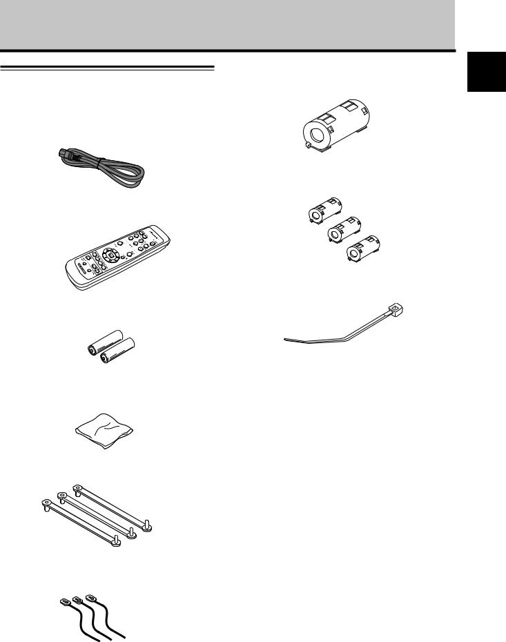
7 Ferrite core (for power cord) |
Check that the following accessories were supplied.
1 Power cord
8 Ferrite cores (x 3) (for audio cables)
2 Remote control unit
9 Cable tie
3 AA (R6) batteries (x 2)
|
÷ |
These Operating Instructions (CD-ROM) |
4 Cleaning cloth (for screen) |
÷ |
Start up Guide |
5 Speed clamps (x 3)
6 Bead band (x 3)
English
3
En
English
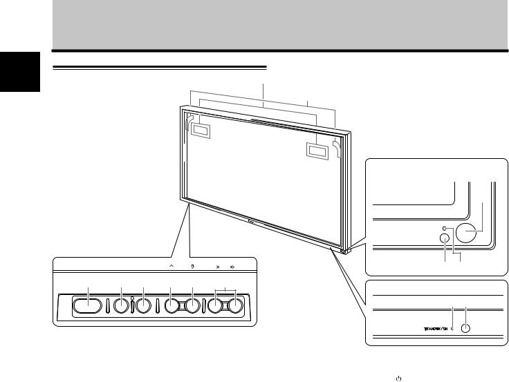
Part Names and Functions
Main unit |
4 (PDP-50MXE20/PDP-50MXE20-S) |
|
4 (PDP-60MXE20) |
|
Main unit |
PDP-50MXE20/
PDP-50MXE20-S
1
STANDBY
Operation panel on the ON main unit
STANDBY/ON |
MENU |
DISPLAY |
INPUT SCREEN SIZE – VOL + |
2 3 |
||
/ SET |
|
|
|
|||
5 |
6 |
7 |
8 |
9 |
0 |
PDP-60MXE20 |
|
|
|
|
|
|
|
|
|
|
|
|
|
3 1 |
Main unit
1 Remote control sensor |
5 STANDBY/ON button ( ) |
|
Point the remote control toward the remote sensor to |
Press to put the display in operation or standby mode. |
|
|
||
operate the unit. |
6 MENU button |
|
2 Ambient light sensor (PDP-50MXE20/PDP- |
Press to open and close the on-screen menu. |
|
7 DISPLAY/SET button |
||
50MXE20-S) |
||
|
This sensor measures the level of light inside the viewing room; it is enabled when the [ENERGY SAVE] option is set to [AUTO].
3 STANDBY/ON indicator
8 INPUT (’) button
When the unit is operating: The indicator lights green.
When flashing, the indicator is used to indicate error
messages. 9 SCREEN SIZE (‘) button
The indicator flashes green once every one second when the [POWER MGT.] function is operating.
When the unit is in standby mode: The indicator lights red.
When flashing, the indicator is used to indicate error messages.
4 Handles
4
En
Part Names and Functions
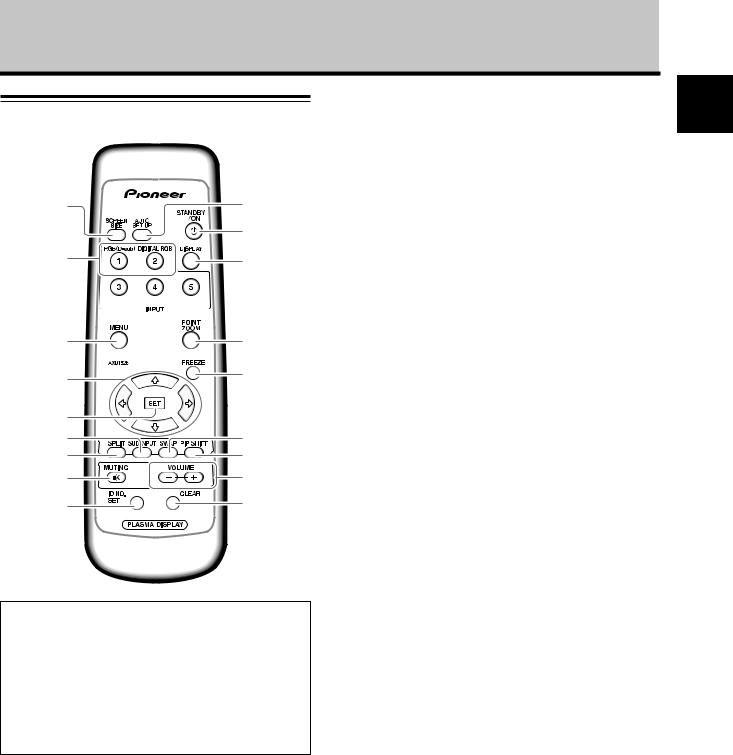
Remote control unit
1 0
-
2 |
= |
3 |
~ |
4 |
! |
|
|
5 |
|
6 |
@ |
7 |
# |
8 |
$ |
9 |
% |
When handling the remote control unit
¶Do not drop the remote control unit or expose it to moisture.
¶Do not use the remote control unit in a location subject to direct sunlight, heat radiation from a heater, or in a place subject to excessive humidity.
¶When the remote control unit’s batteries begin to wear out, the operable distance will gradually become shorter. When this occurs, replace all batteries with new ones as soon as possible.
1SCREEN SIZE button
Press to select the screen size.
2INPUT buttons
Press to select the input.
3MENU button
Press to open and close the on-screen menu.
4ADJUST (5/∞/3/2) buttons
Use to navigate menu screens and to adjust various settings on the unit.
5SET button
Press to adjust or enter various settings on the unit.
6SUB INPUT button
During multi-screen display, use this button to change inputs to subscreens.
7SPLIT button
Press to switch to multi-screen display.
8MUTING button
Press to mute the volume.
9ID NO. SET button
Button used by professional installers.
0AUTO SET UP button
When using computer signal input, automatically sets the [POSITION], [CLOCK] and [PHASE] to optimum values.
-STANDBY/ON button ( )
)
Press to put the unit in operation or standby mode.
=DISPLAY button
Press to view the unit’s current input and setup mode.
~POINT ZOOM button
Use to select and enlarge one part of the screen.
!FREEZE button
When memo screen function is enabled, a still image is displayed in the subscreen.
@ SWAP button
During multi-screen display, use this button to switch between main screen and subscreen.
#PIP SHIFT button
When using the picture-in-picture mode with multiscreen display, use this button to move the position of subscreen.
$VOLUME (+/–) buttons
Use to adjust the volume.
%CLEAR button
Button used by professional installers.
5
English
En
English
Part Names and Functions
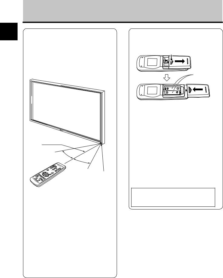
Operating range of the remote control unit
When operating the remote control unit, point it at the remote sensor located on the front panel of the main unit. The remote control unit is operable up to 7 m from the unit and within a 30 angle on each side of the sensor.
Inserting the batteries in the remote control unit
While pressing down lightly, slide in the direction of the arrow.
Two AA (R6) batteries
Designated batteries
Please use size AA (R6) or AA (LR6).
7 m
30°
30°
Remote Sensor
If you are having difficulty with operation of the remote control unit
¶The remote control unit may not operate if there are objects placed between it and the display.
¶Operational distance will gradually become shorter as the batteries begin to wear out, replace weak batteries with new ones as soon as possible.
¶This unit discharges infrared rays from the screen. Placing a video deck or other component that is operated by an infrared remote control unit near this unit may hamper that component’s reception of the remote control’s signal, or prevent it from receiving the signal entirely. Should this occur, move the component to a position further away from this unit.
¶Depending on the installation surroundings, this unit’s remote control unit may be influenced by the infrared rays discharged from the Plasma Display, hampering reception of its rays or limiting its operational distance. The strength of infrared rays discharged from the screen will differ according to the picture displayed.
 CAUTION
¶Do not use batteries other than those designated, and do not mix old and new batteries together, since rupture or leakage may result, leading to danger of fire, personal injury, or contamination.
¶When loading batteries into the remote control unit, insert the batteries with (+) and (–) polarities matching those indicated in the diagram. Inserting batteries incorrectly may result in battery rupture or leakage, leading to danger of fire, personal injury, or contamination.
¶Do not heat or disassemble batteries, and do not dispose of batteries in fire or water, since battery rupture or leakage may result, leading to danger of fire or personal injury.
¶When not using the remote control unit for extended periods of time, remove the batteries and store them separately. Leaving batteries unused in the unit may result in battery leakage, leading to danger of fire, personal injury, or contamination.
When disposing of used batteries, please comply with governmental regulations or environmental public institution’s rules that apply in your country/area.
6
En
Connection panel (PDP-50MXE20/PDP-50MXE20-S)
The connection panel is provided with two video input terminals and one video output terminal. Audio input/ output and speaker output terminals are also provided.
Part Names and Functions
English
-=
IN |
OUT |
|
|
|
OUTPUT INPUT1 INPUT2 |
INPUT1 |
INPUT2 |
|
ANALOG RGB OUT |
ANALOG RGB IN |
DIGITAL RGB |
|
(D-Sub) |
(D-Sub) |
(DVI-D) |
|
|
COMBINATION |
RS-232C |
AUDIO AUDIO AUDIO |
|
|
|
1 |
2 |
3 |
4 |
567 |
8 |
9 |
0 |
1SPEAKER (R) terminal
For connection of an external right speaker. Connect a speaker that has an impedance of 6 Ω.
2SPEAKER (L) terminal
For connection of an external left speaker. Connect a speaker that has an impedance of 6 Ω.
3COMBINATION IN/OUT
Never connect any component to these connectors without first consulting your Pioneer installation technician.
These connectors are used for Plasma Display setup adjustments.
4RS-232C
Never connect any component to this connector without first consulting your Pioneer installation technician.
This connector is used for Plasma Display setup adjustments.
5AUDIO (OUTPUT) (Stereo mini jack)
Use to output the audio of the selected source component connected to this unit to an AV amplifier or similar component.
Note: No sound is produced from the AUDIO (OUTPUT) jack when the MAIN POWER switch is set to OFF or ON (standby).
6AUDIO (INPUT1) (Stereo mini jack)
Use to obtain sound when INPUT1 is selected. Connect the audio output jack of components connected to INPUT1 to this unit.
7AUDIO (INPUT2) (Stereo mini jack)
Use to obtain sound when INPUT2 is selected. Connect the audio output jack of components connected to INPUT2 to this unit.
8ANALOG RGB OUT (INPUT1) (mini D-sub 15 pin)
Use the ANALOG RGB OUT (INPUT1) terminal to output the video signal to an external monitor or other component.
Note: The video signal will not be output from the ANALOG RGB OUT (INPUT1) terminal when the main power of this unit is off or in standby mode.
9ANALOG RGB IN (INPUT1) (mini D-sub 15 pin)
For connection of a personal computer (PC) or similar component. Make sure that the connection made corresponds to the format of the signal output from the connected component.
0DIGITAL RGB (INPUT2) (DVI-D jack)
Use to connect a computer.
-AC IN
Use to connect the supplied power cord to an AC outlet.
=MAIN POWER switch
Use to switch the main power of the unit on and off.
7
En
English
Part Names and Functions
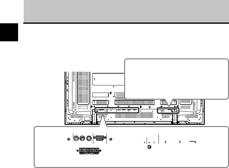
Connection panel (PDP-60MXE20)
The connection panel is provided with two video input terminals and one video output terminal. Audio input/ output and speaker output terminals are also provided.
IN |
OUT |
|
|
COMBINATION |
|
RS-232C |
|
1 |
2 |
3 |
4 |
1COMBINATION IN/OUT
Never connect any component to these connectors without first consulting your Pioneer installation technician.
These connectors are used for Plasma Display setup adjustments.
2SPEAKER (R) terminal
For connection of an external right speaker. Connect a speaker that has an impedance of 6 Ω.
3SPEAKER (L) terminal
For connection of an external left speaker. Connect a speaker that has an impedance of 6 Ω.
4RS-232C
Never connect any component to this connector without first consulting your Pioneer installation technician.
This connector is used for Plasma Display setup adjustments.
5AUDIO (OUTPUT) (Stereo mini jack)
Use to output the audio of the selected source component connected to this unit to an AV amplifier or similar component.
Note: No sound is produced from the AUDIO (OUTPUT) jack when the MAIN POWER switch is set to OFF or ON (standby).
6AUDIO (INPUT1) (Stereo mini jack)
Use to obtain sound when INPUT1 is selected. Connect the audio output jack of components connected to INPUT1 to this unit.
8
- =


OUTPUT |
INPUT1 INPUT2 |
INPUT1 |
INPUT2 |
|
ANALOG RGB OUT |
ANALOG RGB IN |
DIGITAL RGB |
|
(D-Sub) |
(D-Sub) |
(DVI-D) |
AUDIO |
AUDIO AUDIO |
|
|
567 8 9 0
7AUDIO (INPUT2) (Stereo mini jack)
Use to obtain sound when INPUT2 is selected. Connect the audio output jack of components connected to INPUT2 to this unit.
8ANALOG RGB OUT (INPUT1) (mini D-sub 15 pin)
Use the ANALOG RGB OUT (INPUT1) terminal to output the video signal to an external monitor or other component.
Note: The video signal will not be output from the ANALOG RGB OUT (INPUT1) terminal when the main power of this unit is off or in standby mode.
9ANALOG RGB IN (INPUT1) (mini D-sub 15 pin)
For connection of a personal computer (PC) or similar component. Make sure that the connection made corresponds to the format of the signal output from the connected component.
0DIGITAL RGB (INPUT2) (DVI-D jack)
Use to connect a computer.
-AC IN
Use to connect the supplied power cord to an AC outlet.
=MAIN POWER switch
Use to switch the main power of the unit on and off.
En
Installation and Connections
Installation of the unit
Installation using the optional PIONEER stand or other mounting brackets
÷Please be sure to request installation or mounting of this unit by an installation specialist or the dealer where purchased.
 CAUTION
÷Use only those stands or mounting brackets designated by Pioneer. If other non-recommended products are used, the unit may fall and be damaged or otherwise malfunction.
÷Assemble stands or mounting brackets correctly in accordance with the instructions provided or other applicable installation instructions.
÷Two or more people should always work together when installing or removing this unit.
÷The installation location selected should be fully capable of supporting the weight of this unit, and be a stable, flat, and even surface. If installed in other locations, the unit may fall or be damage.
÷After installation, take appropriate measures to prevent the installation from falling. The failure to take such measures could allow the unit to fall, causing injuries or damage.
Wall-mount installation of the unit
This unit has been designed with bolt holes for wall-mount installation, etc. The installation holes provided are shown in the accompanying illustration.
÷Be sure to attach in 4 or more locations above and below, left and right of the center line.
÷Use bolts that are long enough to be inserted 12 mm to 18 mm into the main unit from the attaching surface for both a holes and b holes. Refer to the side view diagram in the accompanying illustration.
÷As this unit is constructed with glass, be sure to install it on a flat, unwarped surface.
 CAUTION
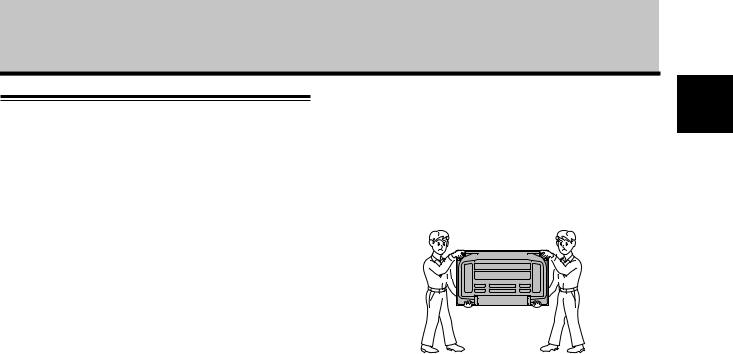
÷Handles should not be removed or reattached by anyone other than the professional installation technician or service personnel.
÷When moving the display, it should always be carried by two persons holding the rear handles in the manner shown.
Never attempt to move the Plasma Display by holding only one of the handles.
 CAUTION
When this unit is installed on a wall, the work should be done by a professional technician possessing the requisite technical knowledge and abilities; consult your dealer for more information. Improper or insufficient installation may result in accidents, damage or personal injury.
English
9
En

English
Installation and Connections
b hole* |
Air vents (fan) |
b hole* |
|
a hole |
|
|
a hole |
|
|
||
|
|
|
|
|
|
|
Attaching surface |
|
|
|
|
|
|
|
Installation |
|
|
|
|
|
|
|
bracket, etc. |
|
|
|
|
|
|
Main unit |
a hole |
|
|
|
|
|
|
|
|
|
|
|
|
|
Center line |
|
Bolt |
|
|
|
|
|
|
|
|
|
a hole |
|
a hole |
|
|
|
|
|
|
|
|
|
|
|
12 mm to 18 mm |
|
|
|
|
|
|
|
Bolt |
|
|
|
|
|
|
b hole |
|
b hole* |
a hole |
Center line |
a hole |
b hole* |
12 mm to 14 mm |
|
|
|
|
|
|
||||
Rear view diagram (PDP-50MXE20/PDP-50MXE20-S) |
Side view diagram |
|
Air vents (fan)
b hole* |
b hole* |
|
Center line |
a hole |
a hole |
Center line
b hole* |
b hole* |
Rear view diagram (PDP-60MXE20)
* Only for speaker unit
10
En
 Loading...