


COMPACT DISC RECORDER / MULTI-CD CHANGER |
×óBÀöù²/ |
|
|
CD SELECT |
OPEN/CLOSE |
OPEN/CLOSE |
|
1 |
|
|
1 |
0 |
3- COMPACT DISC MULTI CHANGER |
2 |
0 |
|
|
COMPACT DISC DIGITAL RECORDER |
||
2 |
0 |
|
3 |
REC/ |
|
|
REC MUTE |
||
|
|
|
CD=CD-R |
|
3 |
0 |
|
START |
¦ |
|
|
|
REC THIS |
|
3-CD CONTROL |
PLAY MODE INPUT |
COPY CONTROL |
¦ REC VOL |
POWER |
41 |
Á¢ DISPLAY |
|
41 |
Á¢ DISPLAY |
|
|
|
KEYBOARD |
|
CHARACTER |
|
|
PHONE |
INPUT |
|
|
6 |
7 |
6 |
7 |
ÑOFF _ON |
|
|
|
CD TEXT LegatoLinkConversion
ORDER NO.
RRV2352
COMPACT DISC RECORDER / MULTI-CD CHANGER
PDR-W839
THIS MANUAL IS APPLICABLE TO THE FOLLOWING MODEL(S) AND TYPE(S).
Type |
Model |
Remarks |
Power Requirement |
||
|
PDR-W839 |
|
KUXJ/CA |
AC120V |
|
WYXJ |
AC220-240V |
|
WVXJ |
AC220-240V |
|
[ EXPLANATORY NOTE ]
•After reparing the unit, make sure to return the operation condition to the shipping position. (for protection during packing)
Refer to P.81 “Setting the initial condition for shippping”.
FOR U.S. MODELS
NECESSARY INFORMATION FOR DHHS RULES MARKED ON THE REAR BASE AND ON THE TOP OF CD MECHANISM AS BELOW.
DANGER – LASER RADIATION WHEN OPEN. AVOID DIRECT EXPOSURE TO BEAM.
CONTENTS
1. SAFETY INFORMATION |
.......................................... |
2 |
|||||||||
|
|
|
|
|
|
||||||
2. EXPLODED VIEWS AND PARTS LIST |
.................... |
4 |
|||||||||
|
|
|
|||||||||
3. BLOCK DIAGRAM AND SCHEMATIC DIAGRAM |
..... |
12 |
|||||||||
|
|||||||||||
4. PCB CONNECTION DIAGRAM |
.............................. |
44 |
|||||||||
|
|
|
|||||||||
5. PCB PARTS LIST |
................................................... |
58 |
|||||||||
|
|
|
|
|
|
|
|||||
6. ADJUSTMENT |
........................................................ |
63 |
|||||||||
|
|
|
|
|
|
|
|
|
|||
7. GENERAL INFORMATION |
..................................... |
77 |
|||||||||
|
|
|
|
||||||||
7.1 DIAGNOSIS |
...................................................... |
77 |
|||||||||
|
|
|
|
|
|
|
|
||||
7.1.1 ERROR CODE |
............................................ |
77 |
|||||||||
|
|
|
|
|
|
||||||
7.1.2 SOLUTION OF 3CD TRAY MISMATCHING |
...... |
78 |
|||||||||
|
|||||||||||
7.1.3 POWER ON SEQUENCE |
......................... |
79 |
||||||||
|
|
|
|
|
||||||
7.1.4 ERROR MESSAGE “CHECK TEMP” |
|
....... |
82 |
|||||||
|
|
|
||||||||
7.1.5 CD-R DISC MANUFACTURER CODE |
|
........ |
82 |
|||||||
|
|
|
||||||||
7.1.6 DISASSEMBLY |
........................................ |
83 |
||||||||
|
|
|
|
|
|
|||||
7.1.7 DIAGNOSIS OF MAIN ASSY |
................... |
87 |
||||||||
|
|
|
|
|||||||
7.1.8 DIAGNOSIS OF CD-R CORE ASSY |
........ |
87 |
||||||||
|
|
|
||||||||
7.2 PARTS |
........................................................... |
88 |
||||||||
|
|
|
|
|
|
|
|
|||
7.2.1 IC |
............................................................. |
88 |
||||||||
|
|
|
|
|
|
|
|
|
||
7.2.2 DISPLAY |
................................................ |
102 |
||||||||
|
|
|
|
|
|
|||||
8. PANEL FACILITIES AND SPECIFICATIONS |
..... |
104 |
||||||||
|
||||||||||
PIONEER CORPORATION 4-1, Meguro 1-chome, Meguro-ku, Tokyo 153-8654, Japan PIONEER ELECTRONICS SERVICE, INC. P.O. Box 1760, Long Beach, CA 90801-1760, U.S.A. PIONEER EUROPE NV Haven 1087, Keetberglaan 1, 9120 Melsele, Belgium
PIONEER ELECTRONICS ASIACENTRE PTE. LTD. 253 Alexandra Road, #04-01, Singapore 159936 c PIONEER CORPORATION 2000
T – ZZV AUG. 2000 Printed in Japan
PDR-W839
1. SAFETY INFORMATION
This service manual is intended for qualified service technicians ; it is not meant for the casual do-it- yourselfer. Qualified technicians have the necessary test equipment and tools, and have been trained to properly and safely repair complex products such as those covered by this manual.
Improperly performed repairs can adversely affect the safety and reliability of the product and may void the warranty. If you are not qualified to perform the repair of this product properly and safely, you should not risk trying to do so and refer the repair to a qualified service technician.
WARNING
This product contains lead in solder and certain electrical parts contain chemicals which are known to the state of California to cause cancer, birth defects or other reproductive harm.
Health & Safety Code Section 25249.6 – Proposition 65
NOTICE
(FOR CANADIAN MODEL ONLY)
Fuse symbols  (fast operating fuse) and/or
  (slow operating fuse) on PCB indicate that replacement parts must be of identical designation.
REMARQUE
(POUR MODÈLE CANADIEN SEULEMENT)
Les symboles de fusible  (fusible de type rapide) et/ou
  (fusible de type lent) sur CCI indiquent que les pièces de remplacement doivent avoir la même désignation.
(FOR USA MODEL ONLY)
1. SAFETY PRECAUTIONS
The following check should be performed for the continued protection of the customer and service technician.
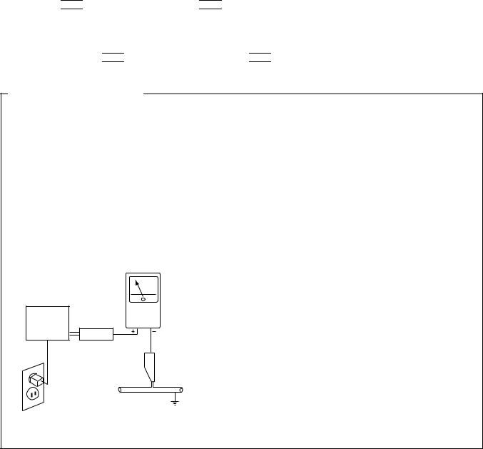
LEAKAGE CURRENT CHECK
Measure leakage current to a known earth ground (water pipe, conduit, etc.) by connecting a leakage current tester such as Simpson Model 229-2 or equivalent between the earth ground and all exposed metal parts of the appliance (input/output terminals, screwheads, metal overlays, control shaft, etc.). Plug the AC line cord of the appliance directly into a 120V AC 60Hz outlet and turn the AC power switch on. Any current measured must not exceed 0.5mA.
|
|
Reading should |
|
Leakage |
not be above |
Device |
current |
0.5mA |
under |
tester |
|
test |
|
|
Test all |
|
|
exposed metal |
|
|
surfaces |
|
|
Also test with |
|
|
plug reversed |
|
Earth |
(Using AC adapter |
|
ground |
plug as required) |
|
|
AC Leakage Test
ANY MEASUREMENTS NOT WITHIN THE LIMITS OUTLINED ABOVE ARE INDICATIVE OF A POTENTIAL SHOCK HAZARD AND MUST BE CORRECTED BEFORE RETURNING THE APPLIANCE TO THE CUSTOMER.
2. PRODUCT SAFETY NOTICE
Many electrical and mechanical parts in the appliance have special safety related characteristics. These are often not evident from visual inspection nor the protection afforded by them necessarily can be obtained by using replacement components rated for voltage, wattage, etc. Replacement parts which have these special safety characteristics are identified in this Service Manual.
Electrical components having such features are identified by marking with a  on the schematics and on the parts list in this Service Manual.
The use of a substitute replacement component which does not have the same safety characteristics as the PIONEER recommended replacement one, shown in the parts list in this Service Manual, may create shock, fire, or other hazards.
Product Safety is continuously under review and new instructions are issued from time to time. For the latest information, always consult the current PIONEER Service Manual. A subscription to, or additional copies of, PIONEER Service Manual may be obtained at a nominal charge from PIONEER.
2
CD RECORDER
IMPORTANT
THIS PIONEER APPARATUS CONTAINS
LASER OF CLASS ΙΙΙ b.
SERVICING OPERATION OF THE APPARATUS
S H O U L D B E D O N E B Y A S P E C I A L L Y
INSTRUTED PERSON.
LASER DIODE CHARACTERISTICS
MAXIMUM OUTPUT POWER: 23 mW
WAVELENGTH: 778 – 787 nm
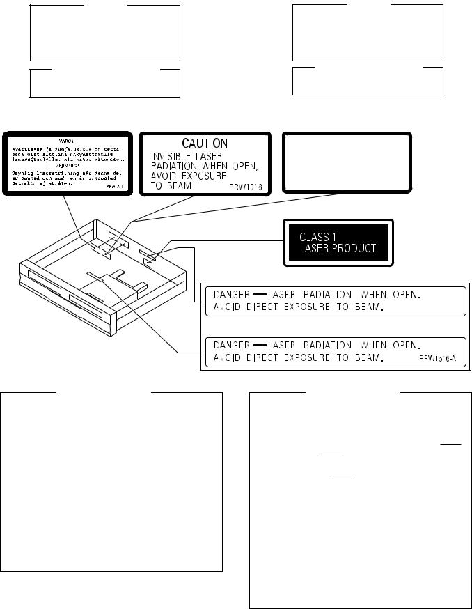
LABEL CHECK
WYXJ Type |
WVXJ Type |
PDR-W839
CD PLAYER
IMPORTANT
THIS PIONEER APPARATUS CONTAINS LASER OF CLASS 1.
SERVICING OPERATION OF THE APPARATUS S H O U L D B E D O N E B Y A S P E C I A L L Y INSTRUCTED PERSON.
LASER DIODE CHARACTERISTICS
MAXIMUM OUTPUT POWER: 5 mW
WAVELENGTH: 760 - 800 nm
WYXJ Type
ADVARSEL
USYNLIG LASERSTRÅLING VED ÅBNING NÅR SIKKERHED SAFBRYDERE ER UDE AF FUNKTION.
UNDGÅ UDSÆTTELSE FOR STRÅLING
VORSICHT!
UNSICHTBARE LASER-STRAHLUNG TRITT AUS, WENN DECKEL (ODER KLAPPE) GEÖFFNET IST! NICHT DEM STRAHL AUSSETZEN!
VRW1094
WYXJ and WVXJ Types
Printed on Rear Panel
KUXJ/CA Type
Printed on Rear Panel
CD RECORDER |
CD PLAYER |
Additional Laser Caution
1.Laser Interlock Mechanism
The position of the switch (S101) on the LOAB Assy for detecting loading state is detected by the system microprocessor, and the design prevents laser diode oscillation when the switch (S101) is not on TRAY terminal side (TRAY signal is OFF or high level.). Thus, the interlock will no longer function if the switch (S101) is
deliberately set to TRAY terminal side (low level).
The interlock also does not function in the test mode . Laser diode oscillation will continue, if pin 1 of CN101 on the CD-R CORE ASSY is connected to low level.
2.When the cover is opened with the servo mechanism block removed and turned over, close viewing of the objective lens with the naked eye will cause exposure to a Class 3 laser beam.
Refer to page 64.
Additional Laser Caution
1.Laser Interlock Mechanism
The position of the switch (S101) on the SELECT UNIT for detecting clamping state is detected by the system microprocessor, and the design prevents laser diode oscillation when the switch (S101) is not on CLMP terminal side (CLMP signal is OFF or high level.). Thus, the interlock will no longer function if the switch (S101) is
deliberately set to CLMP terminal side (low level).
The interlock also does not function in the test mode . Laser diode oscillation will continue, if pin 9 of TA2150FN (IC1101) on the 3CD ASSY is connected to GND, or pin 26 is connected to low level (ON), or else the terminals of Q1101 are shorted to each other (fault condition).
2.When the cover is opened with the servo mechanism block removed and turned over, close viewing of the objective lens with the naked eye will cause exposure to a Class 1 laser beam.
Refer to page 63.
3

PDR-W839
2. EXPLODED VIEWS AND PARTS LIST
NOTES: |
∙ Parts marked by "NSP" are generally unavailable because they are not in our Master Spare Parts List. |
||||||
|
∙ The mark found on some component parts indicates the importance of the safety factor of the part. |
||||||
|
Therefore, when replacing, be sure to use parts of identical designation. |
|
|||||
|
∙ Screws adjacent to |
mark on the product are used for disassembly. |
|
|
|||
2.1 PACKING |
6 |
12 |
3 |
|
|
|
|
|
|
|
|
|
|
|
|
|
13 |
|
|
(1) PACKING PARTS LIST |
|
||
|
|
|
Mark |
No. |
Description |
Part No. |
|
|
|
7 |
|
||||
|
|
|
|
|
|
|
|
|
|
1 |
KUXJ/CA and |
1 |
AC Power Cord |
See Contrast table (2) |
|
|
|
|
WYXJ Types |
2 |
Fuse (T5A) |
See Contrast table (2) |
|
|
|
|
Only |
|
3 |
Stereo Audio Cord (1m) |
RDE1036 |
|
|
|
KUXJ/CA and |
4 |
Operating Instructions |
See Contrast table (2) |
|
|
|
4 |
|
(English) |
|
||
|
|
|
WVXJ Types |
|
|
|
|
|
|
|
Only |
|
5 |
Sub Manual (English) |
See Contrast table (2) |
|
|
|
KUXJ/CA Type |
||||
|
|
5 |
6 |
Remote Control Unit |
PWW1171 |
||
|
|
|
Only |
|
7 |
Battery Cover |
RZN1156 |
|
|
10 |
|
8 |
Operating Instructions |
See Contrast table (2) |
|
|
|
|
|
(German/Italian) |
|
||
|
|
|
|
|
|
|
|
|
|
21 |
|
9 |
Operating Instructions |
See Contrast table (2) |
WYXJ Type Only |
|
|
|
|
(Dutch/Swedish) |
|
|
|
NSP |
10 |
Warranty Card |
See Contrast table (2) |
|
|
|
20 |
||||
13 |
8 |
|
11 |
V Spacer |
See Contrast table (2) |
|
|
|
|||||
|
|
18 |
NSP |
12 |
Dry Cell Battery (R6P, AA) |
VEM-013 |
|
|
|
|
|
|
|
|
|
|
|
13 |
Polyethylene Bag |
Z21-038 |
9 |
|
19 |
|
|
(230 × 340 × 0.03) |
|
14 (2/2) |
|
|
|
14 |
Protector F |
PHA1347 |
|
|
|
15 |
Protector R |
PHA1348 |
|
|
|
|
|
|||
|
|
|
|
16 |
Packing Case |
See Contrast table (2) |
14 (1/2)
15 (1/2)
15 (2/2)
WVXJ Type Only
17 |
11 |
1 |
2 |
16 |
17 |
Mirror Mat Sheet |
Z23-007 |
|
(750 × 600 × 0.5) |
|
18 |
Operating Instructions |
See Contrast table (2) |
|
(Spanish/Danish) |
|
19 |
Operating Instructions |
See Contrast table (2) |
|
(English/French) |
|
20 |
Keypad Stickers |
See Contrast table (2) |
21 |
Caution |
See Contrast table (2) |
(2) CONTRAST TABLE
PDR-W839/KUXJ/CA, WYXJ and WVXJ Types are constructed the same except for the following :
Mark |
No. |
Symbol and Description |
|
Part No. |
|
Remarks |
|
|
|
|
|||||
KUXJ/CA Type |
WYXJ Type |
WVXJ Type |
|||||
|
|
|
|
||||
|
|
|
|
|
|
|
|
|
1 |
AC Power Cord |
ADG7022 |
ADG1154 |
ADG1156 |
|
|
|
2 |
Fuse (T5A) |
Not used |
Not used |
AEK1046 |
|
|
|
4 |
Operating Instructions (English) |
PRB1307 |
Not used |
PRB1307 |
|
|
|
5 |
Sub Manual (English) |
PRB1308 |
Not used |
Not used |
|
|
|
8 |
Operating Instructions (German/Italian) |
Not used |
PRD1061 |
Not used |
|
|
|
9 |
Operating Instructions (Dutch/Swedish) |
Not used |
PRD1062 |
Not used |
|
|
NSP |
10 |
Warranty Card |
ARY7045 |
ARY7022 |
ARY7022 |
|
|
|
11 |
V Spacer |
Not used |
Not used |
PHC1094 |
|
|
|
16 |
Packing Case |
PHG2422 |
PHG2423 |
PHG2424 |
|
|
|
18 |
Operating Instructions (Spanish/Portuguese) |
Not used |
PRD1063 |
Not used |
|
|
|
19 |
Operating Instructions (English/French) |
Not used |
PRE1293 |
Not used |
|
|
|
20 |
Keypad Stickers |
Not used |
PRW1581 |
Not used |
|
|
|
21 |
Caution |
PRM1077 |
PRM1075 |
PRM1077 |
|
|
|
|
|
|
|
|
|
4
PDR-W839
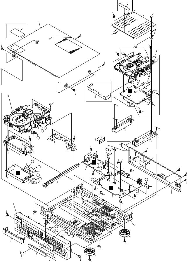
2.2 EXTERIOR SECTION |
32 |
KUXJ/CA |
|
|
|
Type Only |
|
|
39 |
17 |
39 |
|
25 |
||
|
|
||
|
|
|
KUXJ/CA |
18 |
|
|
Type Only |
|
|
|
|
35 |
|
|
|
39 |
|
|
|
|
|
Refer to |
|
|
|
"2.4 CD-R CORE |
44 |
|
39 |
(Mechanism) |
|
ASSY (1/2)". |
||
|
|
||
|
|
|
|
|
|
39 |
4 |
|
|
|
|
|
|
M |
|
|
39 |
|
K |
|
|
|
|
|
J |
M |
I |
|
|
|
F |
|
Refer to |
|
6 |
|
|
|
A |
|
K |
|
"2.6 3CD MICROCHANGER MECHANISM". |
|
|
|
|
5 |
44 |
|
|
H |
|
|
|
||
|
|
|
|
|
39 |
26 |
|
|
|
KUXJ/CA |
J |
|
I |
|
|
|
|||
|
Type Only |
|
|
L |
|
|
|
|
|
|
|
|
|
40 |
|
|
38 |
|
|
|
|
|
|
10 |
D |
|
|
|
|
38 |
|
|
|
|
C |
|
|
|
22 |
||
|
|
|
|
38 |
|
|
|
|||
|
|
|
38 |
|
|
|
|
|
||
|
|
|
|
|
|
WYXJ and |
|
|||
|
|
|
|
|
|
|
|
|||
|
|
|
12 B |
|
|
|
|
|||
|
|
|
|
|
E |
WVXJ Types Only |
|
|||
|
|
O |
|
|
23 |
|
39 |
36 or 37 |
|
21 |
24 |
|
|
|
|
|
|
13 |
|
|
39 |
|
|
|
|
|
|
F |
|
(WYXJ Type Only) |
||
39 |
|
|
|
|
|
|
|
G |
|
|
|
|
|
|
|
|
11 |
|
41 |
||
|
|
|
|
|
|
39 |
42 |
|||
2 |
|
|
|
|
|
|
|
|
||
|
8 |
D |
|
|
|
M |
|
|
|
|
|
|
|
|
|
|
|
39 |
|||
|
|
|
|
|
|
|
|
|
||
|
|
|
|
E |
|
|
|
|
|
|
|
|
|
|
|
|
|
|
|
|
|
|
D |
|
|
|
14 |
|
3 |
|
39 |
|
|
|
|
C |
|
28 |
|
|
|
||
|
|
|
|
|
|
|
|
|
||
39 |
|
|
|
B |
|
|
A |
|
|
H |
|
|
|
|
|
|
|
39 |
|||
|
|
|
9 |
|
43 |
|
|
|
16 |
|
|
|
|
|
|
28 |
H |
|
|||
|
|
|
|
|
|
|
L |
|||
|
|
|
|
|
|
|
|
|
|
|
Refer to |
|
|
|
|
|
|
15 |
7 |
19 |
|
|
|
|
|
|
|
|
1 |
|
|
|
"2.3 FRONT PANEL SECTION". |
|
|
|
|
|
|||||
|
|
|
|
|
|
|||||
39 |
|
|
|
|
|
|
|
|
15 |
|
|
|
|
|
|
|
|
|
|
|
|
|
|
|
27 |
38 |
|
|
|
|
|
|
|
|
|
|
|
|
|
|
|
||
|
|
|
|
|
17 G |
|
|
|
20 |
|
|
|
|
|
|
O |
|
|
|
|
|
|
|
|
|
|
|
|
|
|
|
|
|
|
|
|
|
|
A |
|
|
29 |
|
|
|
|
|
|
|
|
|
|
|
|
30 |
|
|
|
|
|
|
|
|
39 |
|
|
|
|
|
|
|
|
|
|
|
|
|
|
|
|
|
|
|
27 |
|
|
|
|
34 |
|
31 |
|
|
29 |
|
|
|
|
|
|
|
|
33 |
39 |
39 |
|
|
|
|
|
|
|
|
|
|
|
|
|||
39
39
5

PDR-W839
(1) EXTERIOR SECTION PARTS LIST
Mark |
No. |
Description |
|
|
Part No. |
|
Mark |
No. |
Description |
|
Part No. |
|
1 |
MAIN Assy |
See Contrast table (2) |
NSP |
21 |
Mechanism Base 839RR |
|
PNB1625 |
|||
|
2 |
3CD CORE Assy |
PWM2334 |
NSP |
22 |
Mechanism Base 839RL |
|
PNB1626 |
|||
|
3 |
POWER SUPPLY UNIT |
PWR1029 |
NSP |
23 |
3CD Mechanism Base R |
|
PNB1627 |
|||
NSP |
4 |
CD-R CORE (Mechanism) Assy |
PXA1631 |
NSP |
24 |
3CD Mechanism Base F |
|
PNB1628 |
|||
NSP |
5 |
3CD Microchanger Mechanism |
AXA7096 |
|
25 |
Shield Case |
|
PNB1630 |
|||
|
6 |
CD-R CORE (PCB) Assy |
PYY1286 |
|
26 |
Shield Plate |
|
See Contrast table (2) |
|||
|
7 |
9P Flat Flexible Cable/30V |
PDD1218 |
|
27 |
Disc Guard |
|
PNM1245 |
|||
|
8 |
16P Flat Flexible Cable/30V |
PDD1223 |
NSP |
28 |
PCB Holder |
|
PNW2029 |
|||
|
9 |
Connector Assy (7P) |
PDE1309 |
|
29 |
Insulator |
|
PNW2766 |
|||
|
10 |
Connector Assy (6P) |
PDE1310 |
|
30 |
Tray Panel C |
|
PNW2936 |
|||
|
11 |
Connector Assy |
PG06KK-F20 |
|
31 |
Tray Panel B R |
|
PNW2981 |
|||
|
12 |
Connector Assy |
PG11KK-E07 |
NSP |
32 |
Laser Caution Label |
|
See Contrast table (2) |
|||
|
13 |
Power Socket |
See Contrast table (2) |
|
33 |
Getter W739 KU |
|
PRW1542 |
|||
|
14 |
33P Flat Flexible Cable/30V |
PDD1215 |
|
34 |
CDR Getter |
|
AAX7837 |
|||
|
15 |
PCB Mold |
AMR2533 |
|
35 |
Disc Caution Label |
|
See Contrast table (2) |
|||
|
16 |
25P Flat Flexible Cable/30V |
PDD1217 |
|
36 |
Caution Label |
|
See Contrast table (2) |
|||
NSP |
17 |
Cord Stopper |
DNF1128 |
|
37 |
Caution Label HE |
|
See Contrast table (2) |
|||
|
18 |
Bonnet Case BR |
PYY1283 |
|
38 |
Screw |
|
ABA1207 |
|||
|
19 |
Rear Base |
See Contrast table (2) |
|
39 |
Screw |
|
BBZ30P080FCC |
|||
NSP |
20 |
Under Base |
PNA2561 |
|
40 |
Screw |
|
PPZ30P080FMC |
|||
|
|
|
|
|
|
|
|
41 |
Caution Label |
|
See Contrast table (2) |
|
|
|
|
|
|
|
|
42 |
Screw |
|
IBZ30P180FMC |
|
|
|
|
|
|
|
|
43 |
Power Button B |
|
PAC2009 |
|
|
|
|
|
|
|
|
44 |
Screw |
|
FBT40P080FZK |
(2) CONTRAST TABLE
PDR-W839/KUXJ/CA, WYXJ and WVXJ Types are constructed the same except for the following :
Mark |
No. |
Symbol and Description |
|
Part No. |
|
Remarks |
|
|
|
|
|||||
KUXJ/CA Type |
WYXJ Type |
WVXJ Type |
|||||
|
|
|
|
||||
|
|
|
|
|
|
|
|
|
1 |
MAIN Assy |
PWM2325 |
PWM2326 |
PWM2326 |
|
|
|
13 |
Power Socket |
AKP7032 |
Not used |
Not used |
|
|
|
13 |
1P AC Inlet |
Not used |
BKP1046 |
BKP1046 |
|
|
|
19 |
Rear Base 839KU |
PNA2554 |
Not used |
Not used |
|
|
|
19 |
Rear Base 839WY |
Not used |
PNA2553 |
PNA2553 |
|
|
|
26 |
Shield Plate |
PNB1631 |
Not used |
Not used |
|
|
NSP |
32 |
Laser Caution Label |
PRW1516 |
Not used |
Not used |
|
|
|
35 |
Disc Caution Label |
PRW1551 |
Not used |
Not used |
|
|
|
36 |
Caution Label |
Not used |
Not used |
PRW1018 |
|
|
|
37 |
Caution Label HE |
Not used |
PRW1233 |
Not used |
|
|
|
41 |
Caution Label |
Not used |
VRW1094 |
Not used |
|
|
|
|
|
|
|
|
|
6

PDR-W839
2.3 FRONT PANEL SECTION
|
18 |
18 |
|
|
|
2 |
18 |
|
3 |
18 |
|
|
|
|
|
|
9 |
|
|
|
18 |
|
I |
|
7 |
19 |
|
|
1 |
||
|
|
||
|
|
|
|
|
10 |
L |
|
|
|
18 |
|
|
|
4 |
|
14 |
13 |
12 |
|
|
|
||
|
|
|
|
|
|
|
5 |
|
11 |
7 |
|
|
|
|
|
|
|
|
8 |
|
|
16 |
|
|
|
|
17 |
|
15 |
|
CUT |
6
(1) FRONT PANEL SECTION PARTS LIST
Mark No. |
Description |
|
Part No. |
Mark No. |
Description |
|
Part No. |
||
|
1 |
OPERATING 1 Assy |
|
See Contrast table (2) |
|
11 |
Front Panel |
|
See Contrast table (2) |
2 |
OPERATING 2 Assy |
|
See Contrast table (2) |
12 |
Mode Button B |
|
PAC2011 |
||
3 |
OPERATING 3 Assy |
|
See Contrast table (2) |
13 |
Self-Lighted Button |
|
PAC2023 |
||
4 |
HEADPHONE Assy |
|
See Contrast table (2) |
14 |
Pioneer Badge |
|
PAM1776 |
||
5 |
22P Flat Flexible Cable/60V |
|
PDD1214 |
15 |
Display Panel |
|
See Contrast table (2) |
||
6 |
JOG Knob D508 |
|
PAC1939 |
16 |
LED Lens |
|
PNW2745 |
||
7 |
Play Button |
|
PAC1979 |
17 |
REC Ring |
|
PNW2795 |
||
8 |
Operation Button |
|
PAC1980 |
18 |
Screw |
|
PPZ30P080FZK |
||
9 |
O/C Button |
|
PAC1982 |
19 |
Screw |
|
ABA7009 |
||
10 |
Random Button |
|
PAC1996 |
|
|
|
|
|
|
(2) CONTRAST TABLE
PDR-W839/KUXJ/CA, WYXJ and WVXJ Types are constructed the same except for the following :
Mark |
No. |
Symbol and Description |
|
Part No. |
|
Remarks |
|
|
|
|
|||||
KUXJ/CA Type |
WYXJ Type |
WVXJ Type |
|||||
|
|
|
|
||||
|
|
|
|
|
|
|
|
|
1 |
OPERATING 1 Assy |
PWZ4133 |
PWZ4134 |
PWZ4134 |
|
|
|
2 |
OPERATING 2 Assy |
PWZ4141 |
PWZ4142 |
PWZ4142 |
|
|
|
3 |
OPERATING 3 Assy |
PWZ4149 |
PWZ4150 |
PWZ4150 |
|
|
|
4 |
HEADPHONE Assy |
PWZ4157 |
PWZ4158 |
PWZ4158 |
|
|
|
11 |
Front Panel 839KU |
PNW2983 |
Not used |
Not used |
|
|
|
11 |
Front Panel 839WY |
Not used |
PNW2979 |
PNW2979 |
|
|
|
15 |
Display Panel OR |
PAM1828 |
Not used |
Not used |
|
|
|
15 |
Display Panel BL EUR |
Not used |
PAM1832 |
PAM1832 |
|
|
|
|
|
|
|
|
|
7
PDR-W839
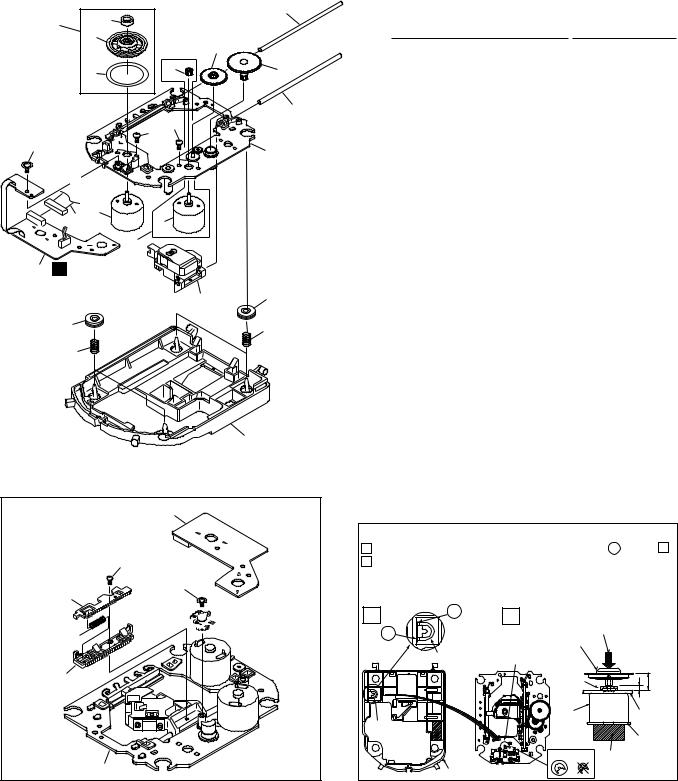
2.4 CD-R CORE (Mechanism) ASSY (1/2)
• Bottom View |
9 |
|
|
|
|
|
|
|
|
8 |
|
1 |
C |
12 |
|
|
|
|
|
|
|
||
|
|
|
17 |
|
|
|
|
|
|
|
|
3 |
|
|
|
|
|
|
|
|
Refer to |
18 |
|
|
|
|
|
|
|
13 |
|
|
"2.5 CD-R CORE ASSY (2/2)". |
|
|
|
|
|
|
|
|
|
|
6 |
|
|
|
|
|
7 |
|
|
|
|
|
5 |
|
|
To |
|
|
4 |
15 |
|
CD-R CORE |
|
|
2 |
CN101 |
||
|
|
|
|
||
|
|
|
|
|
|
|
|
|
14 |
|
|
11 |
16 |
10
∙ CD-R CORE (Mechanism) ASSY(1/2) PARTS LIST
Mark |
No. |
Description |
|
Part No. |
Mark No. |
Description |
|
Part No. |
|
NSP |
1 |
LOAB Assy |
|
VWG2171 |
|
11 |
Tray |
|
VNL1858 |
|
2 |
32P Flexible Cable / 30V |
|
PDD1222 |
12 |
Gear Pulley |
|
VNL1866 |
|
|
3 |
Connector Assy |
|
PG03KK-E07 |
13 |
Loading Gear |
|
VNL1860 |
|
|
4 |
DC Motor (LOADING) |
|
PXM1027 |
14 |
Drive Gear |
|
VNL1861 |
|
|
5 |
Connector Assy 2P |
|
VKP2253 |
15 |
Drive Cam |
|
VNL1862 |
|
|
|
|
|
|
|
|
|||
|
6 |
Motor Pulley |
|
PNW1634 |
16 |
Lock Plate |
|
VNL1820 |
|
|
7 |
Loading Motor Assy |
|
VXX2505 |
17 |
Bridge |
|
VNL1859 |
|
|
8 |
Clamper Plate |
|
VNE2162 |
18 |
Clamper |
|
VNL1738 |
|
|
9 |
Rubber Belt |
|
VEB1315 |
|
|
|
|
|
|
10 |
Loading Base S |
|
PNW2968 |
|
|
|
|
|
8
PDR-W839
2.5 CD-R CORE (Mechanism) ASSY (2/2)
|
|
|
∙ CD-R CORE (Mechanism) ASSY(2/2) |
|||
|
20 |
19 |
PARTS LIST |
|
||
25 |
|
Mark |
No. |
Description |
Part No. |
|
|
|
|||||
15 |
|
|
||||
|
10 |
|
|
|
|
|
|
|
NSP |
1 |
MECHA PCB Assy |
PWX1625 |
|
|
|
|
||||
7 |
9 |
11 |
NSP |
2 |
DC Motor (SPINDLE) |
PXM1044 |
|
|
|
3 |
DC Motor (CARRIAGE) |
PXM1045 |
|
|
|
|
|
4 |
Float Rubber |
PEB1308 |
|
|
18 |
|
5 |
Carriage Motor Assy |
PEA1353 |
|
|
|
|
|
|
|
23 23
22
16
To
CD-CORE
CN452
2
17 |
3 |
|
5
1 B
21 4
4 |
27 |
26 |
(Black) |
|
|
(Gray) |
|
8
∙ Bottom View |
1 |
24
22
14

 12
12
6
13
16
NSP |
6 |
Rack Spring |
DBH1285 |
NSP |
7 |
Reflection Sheet |
PNM1325 |
|
8 |
Float Base |
PNW2964 |
|
9 |
Pinion Gear |
PNW2994 |
|
10 |
Gear A |
PNW2855 |
|
11 |
Gear B |
PNW2856 |
|
12 |
Gear C |
PNW2969 |
|
13 |
Rack |
PNW2965 |
|
14 |
Rack Stopper |
PNW2966 |
NSP |
15 |
Disc Table |
PNW2860 |
|
16 |
Carriage Base |
PNW2967 |
|
17 |
Flexible Cable (08P) |
VDA1822 |
|
18 |
Guide Bar |
VLL1504 |
|
19 |
Sub Guide Bar |
VLL1505 |
NSP |
20 |
Magnet |
VYM1024 |
|
21 |
CD-R Pickup |
PEA1355 |
|
22 |
Screw |
Z39-018 |
|
23 |
Screw |
PMZ20P030FMC |
|
24 |
Screw |
JGZ17P030FMC |
|
25 |
Disc Table Assy |
PEA1349 |
|
26 |
Floating Spring (Gray) |
PBH1232 |
|
27 |
Floating Sprin B (Black) |
PBH1234 |
 How to Install the Disc Table
1 Use nippers or other tool to cut the two sections marked A in figure 1 .
2While supporting the spindle motor shaft with the stopper, put spacer on top of the carriage base, and stick the disc table on top (takes about 9kg pressure). Take off the spacer.
1 |
A |
2 |
|
A |
|
(Pressure of about 9kg) |
|
|
Disc table Assy |
|
|
|
|
|
|
|
Spacer |
Spacer setting |
|
|
Position |
|
|
|
|
Spacer |
11mm |
|
|
|
2.8mm |
|
|
Spindle |
Carriage |
Spacer |
|
motor |
Base |
|
|
|
PCB |
|
|
OK NG |
Stopper |
|
Servo Base |
|
|
9

PDR-W839
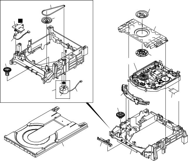
2.6 3CD MICROCHANGER MECHANISM
*1 : Floil (GYA1001) |
|
|
|
|
|
|
|
|
||
*2 : Dyefree (GEM1003) |
|
36 |
|
|
|
|
|
|||
|
|
|
|
|
|
|
|
|
|
|
|
|
|
|
|
|
|
|
37 |
|
|
|
|
|
|
|
36 |
|
|
|
|
|
|
|
|
|
|
|
|
|
|
29 |
|
|
|
|
|
|
36 |
|
|
|
|
|
|
|
|
*2 |
|
|
|
|
|
|
|
|
|
*2 |
(Gutter) |
|
|
|
|
30 |
28 |
|
|
|
|
|
|
|
|
|
|||
|
|
|
|
|
|
|
|
|
|
|
(No.36 Sub Tray Part) |
|
|
|
|
|
|
|
|
||
|
|
|
|
|
*2 |
|
|
|
|
|
|
|
|
|
*2 |
(Bottom Gutter) |
|
|
|
|
|
38 |
|
|
|
|
|
|
|
|
|
|
|
|
|
(Inside Gutter) |
|
|
|
31 |
|
||
*2 |
|
|
|
|
|
*2 |
|
|
|
|
|
|
|
|
|
(Gutter) |
|
|
|
||
(Left Front |
|
|
|
|
|
|
|
|
||
Under Gutter) |
|
|
|
|
*2 |
|
|
|
|
|
35 |
|
|
|
|
|
|
|
|
|
|
|
|
|
|
(Bottom Gutter) |
*1 |
*1 |
|
|
|
|
*2 |
|
|
|
|
|
|
|
|||
|
|
|
|
|
(Boss) |
|
|
|
||
|
33 |
|
|
|
(Gutter) |
|
|
|||
(Whole) |
|
|
|
|
32 |
|
|
27 |
|
|
34 |
|
|
|
|
|
|
|
|
||
|
|
|
|
|
|
|
|
*1 |
|
|
|
|
|
|
|
|
|
|
|
(Gutter) |
|
|
|
41 |
40 |
|
|
|
|
|
|
|
|
|
|
|
|
|
|
|
|
|
|
|
|
|
*1 |
|
|
|
|
|
|
|
|
|
|
(Gutter) |
|
|
|
25 |
|
||
|
|
|
45 |
19 |
|
|
|
|
||
|
|
|
|
|
|
(Blue) |
|
|||
|
42 |
39 |
|
|
|
|
|
|
22 |
|
|
|
|
|
|
|
|
|
20 |
|
|
|
|
|
|
|
|
|
11 |
|
|
|
|
|
*1 |
|
|
12 |
|
|
|
|
|
|
|
|
|
|
|
|
|
|
||
|
(Shaft) |
14 |
|
|
|
|
|
4 |
||
|
|
|
13 |
|
|
43 |
21 |
|||
|
|
|
|
|
|
|
||||
|
|
|
|
|
17 |
|
|
44 |
|
|
|
|
|
|
|
|
|
43 |
23 |
|
|
|
|
18 |
|
|
|
|
*1 |
|
|
|
|
|
|
|
|
|
|
|
|
||
|
|
|
|
|
*1 |
|
(Rail) |
|
|
|
|
|
|
|
|
16 |
|
|
|
||
|
|
|
|
|
|
|
|
|
||
|
|
|
|
|
(Gutter) |
|
|
|
|
|
|
|
|
|
|
|
|
|
24 |
|
|
|
|
|
|
|
|
|
|
|
|
|
|
|
|
*1 |
|
|
|
|
|
|
|
|
|
15 |
(Column) |
|
|
|
|
|
||
|
|
|
|
|
|
|
|
*1 |
|
|
|
|
|
|
|
|
|
|
|
|
|
|
|
|
|
|
|
|
|
|
(Inside Rail) |
|
|
|
|
|
|
|
|
|
8 |
|
|
|
|
|
|
|
|
|
|
|
9 |
|
|
|
|
|
|
|
|
|
*1 |
|
|
|
|
|
|
|
|
|
6 |
(Inside Rail) |
|
|
|
|
|
|
|
|
|
|
|
|
|
|
|
2 |
F |
|
|
7 |
|
|
|
|
|
|
|
|
|
|
|
|
|
||
|
|
|
|
G |
7 |
|
|
|
|
|
|
|
|
3 |
5 |
|
5 |
46 |
10 |
|
|
|
|
|
|
|
|
|
|
|
|
|
 E
E
1
26
(Black)
10
PDR-W839
∙ 3CD MICROCHANGER MECHANISM PARTS LIST
Mark |
No. |
Description |
|
Part No. |
|
1 |
MOTOR Unit |
|
AWU7431 |
|
2 |
LOADING Unit |
|
AWU7432 |
|
3 |
SELECT Unit |
|
AWU7433 |
|
4 |
PICKUP Unit |
|
KSM213CCM |
|
5 |
Carriage Motor |
|
VXM1033 |
|
6 |
Mechanism Base |
|
ANW7129 |
|
7 |
Motor Pulley |
|
PNW1634 |
|
8 |
Lift Spring |
|
ABH7173 |
|
9 |
Home Lever |
|
ANW7153 |
|
10 |
HL Spring 2 |
|
ABH7182 |
|
11 |
Extended Gear A |
|
ANW7138 |
|
12 |
Gear A |
|
ANW7136 |
|
13 |
Extended Gear B |
|
ANW7139 |
|
14 |
Gear B |
|
ANW7137 |
|
15 |
Gear Pully |
|
ANW7135 |
|
16 |
Select Lever |
|
ANW7143 |
|
17 |
EV Cam gear |
|
ANW7140 |
|
18 |
Belt |
|
AEB7159 |
|
19 |
Elevator Base |
|
ANW7132 |
|
20 |
Tray Guide |
|
ANW7150 |
|
21 |
TG Stopper |
|
ANW7151 |
|
22 |
TG Spring |
|
ABH7175 |
|
23 |
Cam Plate |
|
ANW7147 |
|
24 |
Lock Lever |
|
ANW7148 |
|
25 |
Float Rubber A (Blue) |
|
AEB7063 |
|
26 |
Float Rubber B (Black) |
|
AEB7066 |
|
27 |
Float Base |
|
ANW7130 |
|
28 |
Clamper Holder |
|
ANW7152 |
|
29 |
Yoke |
|
ANG7257 |
|
30 |
Clamper Magnet |
|
AMF7001 |
|
31 |
Clamper SO |
|
XNW3007 |
|
32 |
Swing Base |
|
ANW7131 |
|
33 |
Main Tray |
|
ANW7133 |
|
34 |
Lock Plate |
|
ANW7144 |
|
35 |
Lock Plate Spring |
|
ABH7174 |
|
36 |
SUB Tray |
|
ANW7134 |
|
37 |
Tray Label |
|
ARW7070 |
|
38 |
Stopper Arm |
|
ANW7145 |
|
39 |
Gear Shaft |
|
ANW7142 |
|
40 |
Loading Gear |
|
ANW7141 |
|
41 |
Elevator |
|
ANW7207 |
|
42 |
Elevator Cover |
|
ANW7206 |
NSP |
43 |
MB Spacer |
|
AEC7259 |
NSP |
44 |
MB3 Spacer |
|
AEC7263 |
|
45 |
Loading Gear 2 |
|
ANW7195 |
|
46 |
Spring Support |
|
ANG7342 |
11
PDR-W839
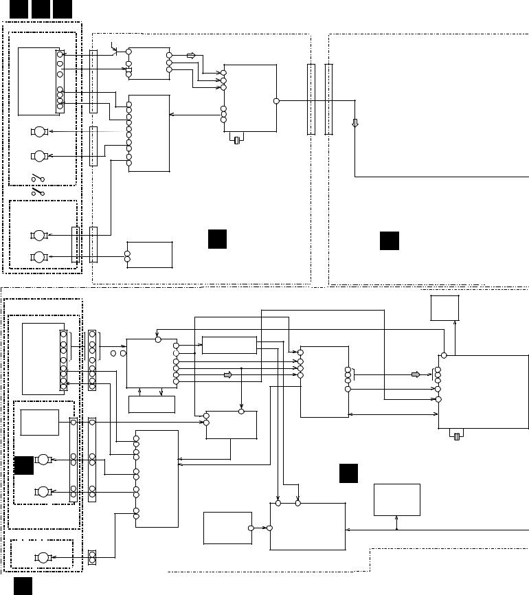
3. BLOCK DIAGRAM AND SCHEMATIC DIAGRAM
3.1 BLOCK DIAGRAM
AWU7431 E F G AWU7432AWU7433
3CD MECHA. Ass’y
CD PICKUP unit |
|
|
|
|
|
|
|
|
|
|
|
|
KSM213CCM |
CN1101 |
|
|
|
|
|
|
|
|
|
|
|
|
|
LD |
1 |
|
RFGO |
|
|
|
|
|
|
|
|
10 |
|
IC1101 |
|
|
|
|
|
|
|||
|
|
|
25 |
TEO |
|
|
|
CN1201 |
CN902 |
|
||
|
3 |
|
6 |
TA2150FN 14 |
|
|
|
|
||||
|
A –F |
FEO |
|
|
|
|
|
|
||||
|
– |
|
– |
RF AMP |
16 |
|
|
38 |
|
|
|
|
CD |
8 |
|
11 |
|
|
|
|
|
|
|
||
|
|
|
|
|
|
|
|
|
|
|||
|
|
|
|
|
|
|
46 |
|
|
|
|
|
PickUp |
|
|
|
|
|
|
|
|
|
|
|
|
13 |
|
|
|
|
|
|
43 |
IC1201 |
|
|
|
|
|
|
|
|
|
|
|
|
|
|
|
||
|
14 |
|
|
|
|
|
|
|
DOUT |
|
|
|
|
|
|
|
|
|
|
|
TC9495F |
|
|
||
|
15 |
|
|
|
|
|
|
|
|
|
||
|
F+/- 34 |
IC1301 |
|
|
|
|
9 |
|
|
|||
|
16 |
|
|
FOO |
48 |
CD DECORDER |
|
|
|
|||
|
|
|
35 |
M56788FP |
|
|
TRO |
|
|
|
||
|
|
T+/- |
|
|
FMO |
49 |
|
|
|
|
||
|
|
31 |
DRIVER |
|
|
|
|
|
|
|
||
SPINDLE MOTOR |
|
|
|
53 |
|
|
|
|
||||
CN1301 |
32 |
|
|
|
|
|
|
|
||||
|
|
|
|
|
|
|
|
|
||||
M |
|
SP+/- |
9 |
|
|
|
|
|
|
|
|
|
|
|
FCS |
|
|
|
|
|
|
|
|
||
|
|
10 |
|
|
|
|
X1201 |
|
|
|
||
|
|
|
|
|
|
|
|
|
|
|||
SLED MOTOR |
SL+/- |
12 |
TRK |
|
|
|
|
|
|
|
|
|
|
13 |
SPDL |
|
|
|
|
16.93MHz |
|
|
|
||
M |
|
LO+/- |
14 |
SLED |
|
|
|
|
|
|
|
|
INSIDE SW |
|
|
15 |
LOADING |
|
|
|
|
|
|
|
|
|
|
|
|
|
|
|
|
|
|
|
|
|
LOADING/SELECT |
|
|
|
|
|
3CD CORE ASSY |
MAIN ASS’Y |
|||||
|
|
|
|
|
(KUXJ/CA |
: PWM2325) |
||||||
UUNIT |
|
|
|
|
|
|
PWM2334 |
|
||||
|
|
|
|
|
|
|
(WYXJ,WVXJ : PWM2326) |
|||||
LOADING MOTOR |
CN1302 |
|
|
|
|
|
||||||
|
|
|
|
|
D |
|
|
|
|
|||
M |
|
|
|
|
|
|
|
|
H |
|
||
SELECT MOTOR |
|
1 |
IC1302 |
|
|
|
|
|
||||
M |
|
|
B A6417F |
|
|
|
|
|
|
|
|
|
|
|
7 |
|
|
|
|
|
|
|
|
||
|
|
|
MOTOR DRIVER |
|
|
|
|
|
|
|||
CD-R CORE MECHA. |
IC504 |
|
|
|
|
|
|
|
|
|
|
|
|
|
|
|
|
|
|
PCX1027 |
|
|
|
|
|
|
|
|
|
|
|
|
|
|
|
|
|
|
|
VCO |
|
CN1 |
CN101 |
|
|
|
|
|
|
|
|
|
|
|
|
|
|
||
|
|
|
|
|
|
|
|
IC251-IC254 |
|
|
|
|
|
|
|
|||
|
|
17 |
17 |
|
17.2872MHz |
|
|
|
|
|
|
|
|
|
|
|||
|
|
– |
– |
A-H |
|
48 |
|
WRF |
|
|
RUNNING OPC |
|
|
|
|
|
|
|
|
|
20 |
20 |
|
89 |
|
|
|
|
|
|
|
|
|
||||
CD-R |
|
|
|
|
|
CIRCUIT BLOCK |
|
|
|
|
|
|
|
|||||
23 |
23 |
91 - 98 |
|
|
88 RFDC |
|
|
|
43 |
|
|
|
|
|||||
|
IC101 |
|
|
|
|
|
|
|
|
|
||||||||
– |
– |
|
|
|
|
|
|
|
CDLRCK |
CDLRCK |
58 |
|||||||
PickUp |
|
|
|
FE |
|
|
|
|
|
|
|
|||||||
26 |
26 |
|
|
|
|
|
|
|
|
39 |
|
|
||||||
|
|
A K8567 |
10 |
|
|
|
|
|
|
CDBCK |
CDBCK |
|
||||||
PEA1356 32 |
32 |
|
|
9 |
TE |
|
|
|
|
|
41 |
|
CDDATA |
CDDATA |
||||
|
|
|
|
|
|
|
|
|
IC401 |
65 |
|
136 |
||||||
|
|
29 |
29 |
RF PROCESSOR80 |
RFAC |
|
|
|
|
|
50 |
67 |
|
134 |
||||
|
|
31 |
31 |
|
|
|
39 |
RFWBL |
|
|
|
|
|
|
CXD 2585Q |
66 |
|
135 |
|
|
|
|
|
|
|
|
|
|
|
|
|
||||||
|
|
30 |
30 |
|
|
|
|
|
|
|
|
|
|
|
|
CDTX |
CDTX |
|
|
|
|
|
|
|
|
|
|
|
|
|
|
|
CD DECODER 64 |
|
137 |
||
MECHA PCB ASSY |
|
|
LD CONTROL |
|
|
|
|
|
|
|
|
|
|
|
131 |
|||
|
|
|
|
|
|
|
|
|
|
|
|
|
|
|||||
|
|
|
CIRCUIT |
|
|
RFDC |
TE |
|
|
|
|
|
|
|
||||
PC651 |
CN601 |
CN452 |
|
|
|
|
31 |
|
|
|
|
|
|
|
||||
|
|
|
|
FG |
52 |
IC201 |
|
|
|
|
|
|
|
|||||
NJL5809K-F1 |
1 |
1 |
FG |
|
|
|
|
19 |
|
|
|
|
|
|
|
|||
FG Generator |
|
|
|
|
|
|
|
|
|
PA9007A |
|
|
|
|
|
|
X501 |
|
|
|
|
|
|
|
|
|
|
SERVO AMP IC |
|
|
|
|
|
|
|||
|
|
|
|
|
|
|
|
|
|
|
|
|
|
CD-R CORE ASS’Y |
|
|||
SPINDLE MOTOR |
|
FCS+/– 15 |
|
|
|
|
|
|
|
|
|
33.8688MHz |
||||||
|
|
16 |
IC451 |
|
|
|
|
|
|
|
|
|
|
|
||||
|
|
|
|
|
|
|
|
|
|
|
|
|
|
|||||
|
|
|
|
|
|
|
|
|
|
|
PYY1286 |
|
|
|||||
PXM1044 |
7 |
7 |
TRK+/– 17 |
|
|
|
|
|
|
|
|
|
|
|||||
B |
M |
|
18 |
BA5810FP |
|
|
|
|
|
|
|
|
|
|||||
8 |
8 |
|
|
|
|
|
|
|
|
|
|
|
|
|||||
|
|
DRIVER IC |
|
|
|
|
|
|
|
|
|
A |
|
|
||||
|
|
|
|
|
|
|
|
|
|
|
|
|
|
|||||
|
|
|
|
|
|
|
|
|
|
|
|
|
|
|
|
|||
|
|
|
SP+/– |
13 |
|
|
|
|
|
|
|
|
|
|
|
|
||
CARRIAGE MOTOR |
|
|
14 |
TRK |
|
|
|
|
|
|
|
|
|
|
|
|||
|
|
|
|
|
|
|
|
|
|
|
|
|
|
|||||
ASSY |
|
4 |
4 |
SL+/– |
11 |
FCS |
|
|
|
|
|
|
|
|
|
|
IC303 |
|
|
M |
|
|
|
|
|
|
|
|
|
|
|
||||||
|
6 |
6 |
|
12 |
SPDL |
|
|
|
|
|
|
AOUT |
BOUT |
|
PYY1287 |
|
||
PEA1353 |
|
|
|
|
|
|
|
|
|
|||||||||
|
|
|
|
SL D |
|
|
|
|
|
|
|
|
||||||
|
|
|
|
|
|
|
|
|
|
57 |
58 |
|
|
(BR93LC66 F) |
|
|||
PWX1625 |
|
L+/– |
|
LOADING |
|
|
|
|
|
|
|
|
|
|
|
|||
|
9 |
|
|
|
|
IC302 |
|
|
IC301 |
|
EEPROM |
|
||||||
|
|
|
|
|
10 |
|
|
|
|
|
|
|
|
|
|
|||
|
|
|
|
|
|
|
|
|
|
|
MM1522XU |
59 |
|
PE5190A |
|
|
|
|
|
|
|
|
|
|
|
|
|
|
|
4 |
MECHA. CONTROL |
|
|
|
|||
LOAB ASSY |
|
|
|
|
|
|
|
|
TEMPERATURE |
|
|
|
|
|||||
|
|
|
|
|
|
|
|
|
|
μ COM |
|
|
|
|||||
LOADING MOTOR |
|
|
|
|
|
|
|
|
SENSOR IC |
|
|
|
|
|
||||
CN453 |
|
|
|
|
|
|
|
|
|
|
|
|
|
|||||
|
|
|
|
|
|
|
|
|
|
|
|
|
|
|||||
ASSY |
|
|
1 |
|
|
|
|
|
|
|
|
|
|
|
|
|
|
|
|
M |
|
|
|
|
|
|
|
|
|
|
|
|
|
|
|
|
|
VXX2505 |
|
2 |
|
|
|
|
|
|
|
|
|
|
|
|
|
|
|
|
|
|
|
|
|
|
|
|
|
|
|
|
|
|
|
|
|
|
|
C VWG2171 |
|
|
|
|
|
|
|
|
|
|
|
|
|
|
|
|
||
12

PDR-W839
|
CDR CORE ASSY |
|
|
|
|
|||
: 3CD PLAY |
|
CN901 |
|
|
|
|
|
|
: CD-R PLAY |
|
|
|
|
|
|
|
|
|
|
V+5A V+5D |
CN202 |
|
|
|
|
|
CN1101 |
CN201 |
V+6P |
|
|
|
|
|
|
|
POWER SUPPLY UNIT |
|
||||||
|
|
V+8A |
|
|||||
|
|
V+16A |
|
|
PWR1029 |
|
AC IN |
|
|
|
V–16A |
|
|
|
|||
|
|
V+5K |
|
|
|
M |
|
|
|
|
V+6M |
|
|
|
|
|
|
|
|
V+5D |
|
|
|
|
|
|
|
|
VF–24 |
|
|
|
|
|
|
|
|
|
|
AOUTL |
|
IC801 |
|
|
|
|
|
|
|
|
|
||
|
|
|
|
+ / – |
|
|
|
|
|
|
|
|
|
25 |
26 |
2 |
|
|
|
|
|
|
|
3 |
5 |
L |
|
|
|
|
|
|
|
7 |
|
|
|
|
|
IC803 |
NJM2121M |
LINE IN |
||
|
|
|
13 A K4524VF |
|||||
|
|
|
IC802 |
|||||
|
|
|
|
CODEC |
|
|||
|
|
|
11 |
7 |
R |
|||
|
|
|
12 |
|
|
|
||
|
|
|
|
|
2 |
5 |
|
|
|
|
|
14 |
9 |
27 |
28 |
2 |
|
|
|
|
|
|
|
|||
|
|
|
XTI |
|
|
AOUTR |
|
KU type ONLY |
|
|
|
|
|
|
+ / – |
NJM2121M |
|
|
|
|
|
|
|
|
|
|
SR IN
|
|
|
|
|
|
EXCEPT KU type |
|
|
|||
|
|
|
|
DALRCK |
|
|
|
IC402 |
|
|
L |
|
|
|
|
DABCK |
|
|
|
PE8001A |
16 |
|
|
|
|
|
|
DADATA |
|
1 |
|
IC810 |
LINE OUT |
||
|
|
|
|
|
|
|
|
||||
|
|
|
|
|
|
3 |
|
|
|
||
|
|
|
|
|
|
|
|
|
NJM4558MD |
||
|
|
|
|
|
|
2 |
|
D/A |
13 |
|
|
|
|
|
|
|
|
|
|
|
|||
|
|
|
|
IC809 |
|
|
5 |
for output |
|
|
R |
|
|
|
|
|
|
XTI |
|
|
|||
|
|
|
|
|
DACMCK |
|
|
|
|
|
|
|
IC503 |
|
|
|
|
|
|
|
IC811 |
|
|
LC324265AT-25 |
|
|
|
|
|
|
BA4560F |
|
|||
|
|
|
|
|
|
|
|
||||
|
D-RAM |
|
|
|
|
|
|
|
|
|
|
|
Address |
Data |
|
|
|
|
|
|
|
|
|
|
|
|
|
|
|
|
|
|
|
JA602 |
|
|
|
|
|
|
|
|
|
|
|
|
OPTICAL |
|
|
|
CN502 |
CN601 |
|
|
|
|
|
|
DIGITAL IN |
|
|
|
ADDATA |
|
|
|
|
|
|
|
COAXIAL |
IC501 |
85 |
|
|
|
|
|
|
|
|
||
DALRCK |
CD-R PLAY 3CD PLAY |
|
|
|
|
|
|
|
|||
PDC069A |
79 |
DABCK |
|
|
|
|
|
|
|
||
DADATA |
|
|
|
|
|
L611 |
COAXIAL |
||||
|
|
77 |
|
|
|
|
|
|
|||
EFM |
|
|
|
|
|
|
|
||||
78 |
|
|
|
|
|
|
|
|
|||
|
|
|
|
|
|
|
|
DIGITAL OUT |
|||
ENCODER |
160 DIN3 |
|
|
|
|
|
|
|
|||
|
|
|
|
|
|
|
|
JA604 |
|
||
|
|
158 |
DIN1 |
|
|
|
|
|
|
OPTICAL |
|
|
|
DITOUT |
|
IC901 |
|
|
|
|
|
||
|
|
117 |
|
|
|
|
|
|
L |
||
91 |
62 |
|
|
|
|
|
|
|
|||
|
|
|
PD5603A |
|
|
|
|
||||
TX |
DAC CKOUT |
|
|
|
|
|
|||||
|
SYSTEM CONTROL |
|
|
|
|
||||||
AUX |
|
|
|
|
|
|
|
|
|||
|
|
CN302 |
CN904 |
μ-COM |
|
18 |
|
|
|
Headphone |
|
|
3CD PLAY |
|
|
|
|
||||||
|
|
|
|
|
25 |
KEY CLK |
|
CN1301 |
|
||
|
|
|
|
|
1 2 |
67 |
|
KEY DATA |
CN801 |
|
|
|
|
|
|
|
|
|
|
||||
CN901 |
|
HEADPHPONE |
Keyboard IN |
|
|
ASSY |
|
CN701 |
|
|
|
FLD! FLCL |
FLCE |
I J |
|
64 63 62 |
|
|
|
IC701 |
|
K |
|
LC75710NE |
|
|
|
FL DRIVER |
|
|
|
|
|
OPERATIG 1– 3 |
|
|
|
ASS’Y |
|
V701
FL DISPLAY
Key Input
REC VOL. (JOG
with Pus h Button)
OPERATING 1 ASSY |
OPERATING 2 ASSY |
OPERATING 3 ASSY |
HEADPHONE ASSY |
||||
(KUXJ/CA |
: PWZ4133) |
(KUXJ/CA |
: PWZ4141) |
(KUXJ/CA |
: PWZ4149) |
(KUXJ/CA |
: PWZ4157) |
(WYXJ,WVXJ |
: PWZ4134) |
(WYXJ,WVXJ |
: PWZ4142) |
(WYXJ,WVXJ |
: PWZ4150) |
(WYXJ,WVXJ |
: PWZ4158) |
13
|
1 |
|
2 |
|
3 |
|
4 |
|
|
|
|
|
|
PDR-W839
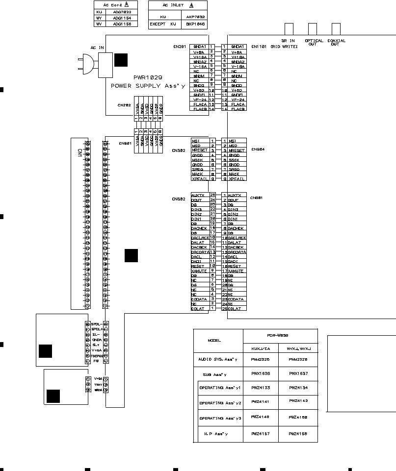
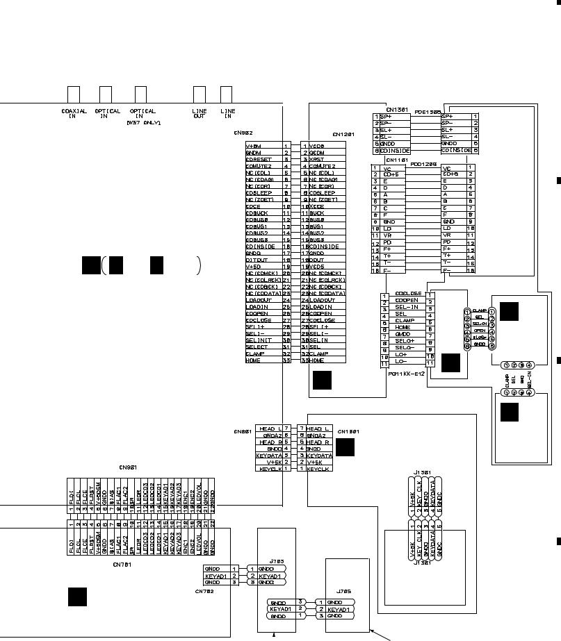
3.2 OVERALL WIRING DIAGRAM
A
B
C
M POWER SUPPLY
UNIT (PWR1029)
|
PDD1222 |
PG06KK-F20 |
|
|
PDD1218 |
|
F- |
CN101 |
|
T- |
|
|
|
|
|
T+ |
|
|
F+ |
|
|
GNDS |
|
|
GNDA |
|
|
F |
|
|
B |
|
CD |
A |
|
H |
|
|
- |
VCC |
|
|
|
|
R |
VC |
|
PICKUP |
GNDA |
|
|
G |
|
|
D |
|
|
C |
|
(PEA1352) |
E |
A |
VC |
||
|
FPDO |
|
|
V+5A |
|
|
V+5A |
|
|
CFREQ |
|
|
CMOD |
|
|
PGND |
CDR CORE ASSY |
|
VRDC |
|
|
VWDC2 |
(PYY1286) |
|
VWDC1 |
|
|
GNDD |
|
|
OSCEN |
|
|
ODON |
|
|
W/XR |
|
|
LDON |
|
B MECHA PCB |
|
|
|
PDD1217 |
|
ASSY (PWX1625) |
CN601 |
CN452 |
|
|
|
C LOAB ASSY (VWG2171) |
CN101 |
CN451 |
|
|
|
D |
|
|
|
|
|
14 |
|
|
|
|
|
1 |
|
|
2 |
3 |
4 |
|
5 |
|
6 |
|
7 |
|
8 |
|
|
|
|
PDR-W839
Note : When ordering service parts, be sure to refer to "EXPLODED VIEWS and
PARTS LIST" or "PCB PARTS LIST".
3CD MICRO CHANGER MECHANISM ASSY (AXA7096)
PDD1215
PICKUP UNIT (KSM213CCM)
H H 1/3- H 3/3
MAIN ASSY |
CN1302 |
CN101 |
|
|
(KUXJ/CA : PWM2325) |
|
|
||
|
UNITMOTOR (AWU7431) |
J102 |
|
|
(WYXJ,WVXJ : PWM2326) |
|
(AWU7432) |
||
|
|
|||
|
|
|
F |
|
|
|
|
|
|
|
|
|
|
LOADING |
|
|
|
|
UNIT |
|
|
J102 |
J101 |
|
|
|
E |
|
|
3CD CORE |
|
|
||
|
|
|
||
D ASSY |
|
|
|
|
(PWM2334) |
|
|
J101 |
|
|
|
|
|
|
PDE1309 |
|
|
|
G |
|
|
|
|
|
|
HEADPHONE ASSY |
|
SELECT |
|
L |
|
UNIT |
||
(KUXJ/CA |
: PWZ4157) |
|
(AWU7433) |
|
|
(WYXJ,WVXJ : PWZ4158) |
|
|
|
PDD1214
KEY BOARD JACK
I OPERATING 1 ASSY (KUXJ/CA : PWZ4133) (WYXJ,WVXJ : PWZ4134)
|
|
|
|
|
|
|
|
|
K |
OPERATING 3 ASSY |
|
J |
OPERATING 2 ASSY |
||||
(KUXJ/CA : PWZ4149) |
|||||
(KUXJ/CA |
: PWZ4141) |
|
|||
|
|
|
|||
(WYXJ,WVXJ : PWZ4142) (WYXJ,WVXJ : PWZ4150)
A
B
C
D
15
|
5 |
|
6 |
|
7 |
|
8 |
|
|
|
|
|
|
||||
|
|
|
|
|
|
1 |
|
2 |
|
3 |
|
4 |
|
|
|
|
|
|
PDR-W839
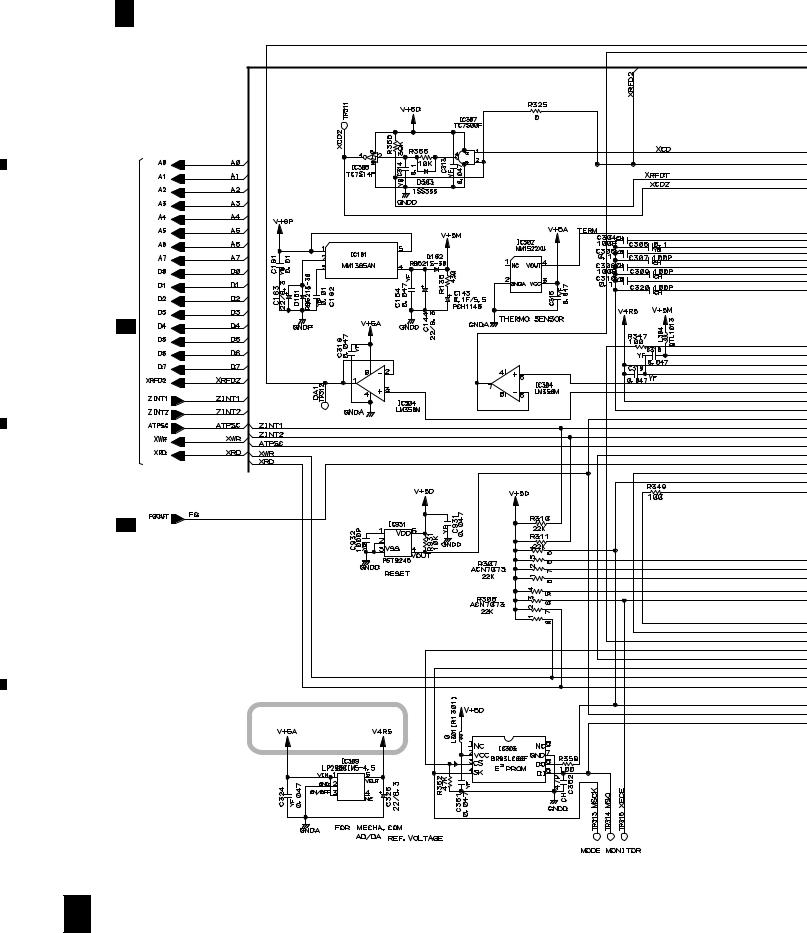
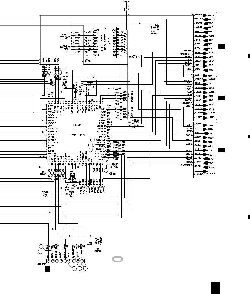
3.3 CD-R CORE ASSY(1/5)
A 1/5
A
CD-R CORE ASSY (PYY1286)
B
A 4/5
A 3/5
Regulator |
C
D
16 A 1/5
|
1 |
|
2 |
|
3 |
|
4 |
|
|
|
|
|
|
||||
|
|
|
|
|
|
5 |
|
6 |
|
7 |
|
8 |
|
|
|
|
|
|
PDR-W839
A
A 3/5
A 2/5
Mecha. Control 10 |
A5/5 |
|
U-com |
8 |
|
|
9 |
|
|
|
7 |
|
|
6 |
2
1 
CN302 |
: The power supply is shown with the marked box. |
|
|
|
H 3/3 CN904 3 4 5 |
A 1/5 17
B
C
D
|
5 |
|
6 |
|
7 |
|
8 |
|
|
|
|
|
|
||||
|
|
|
|
|
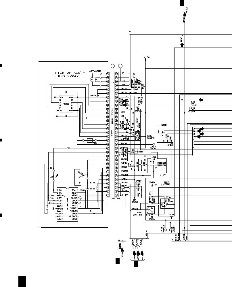
|
1 |
|
2 |
|
3 |
|
4 |
|
|
|
|
|
|
PDR-W839
A 1/5
3.4 CD-R CORE ASSY(2/5)
A |
A |
2 /5 |
CD-R CORE ASSY (PYY1286)
11 |
12 |
B
C |
|
|
|
(R) |
|
|
(R) |
|
|
CN1 CN101 |
|
D |
(R) |
(R) |
|
|
|
|
A 1/5 |
A 4/5 |
|
|
|
18 |
A 2/5 |
|
|
1 |
|
2 |
|
3 |
|
4 |
|
|
|
|
|
|
||||
|
|
|
|
|
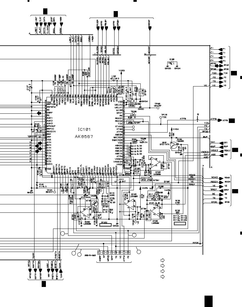
5  6
6
A 1/5 |
A 4/5 |
|
RF PROCESSOR
|
|
F Rank : 1% |
15 |
|
17 |
|
|
|
14 |
CN102 |
16 |
13 |
|
TP_POINT
A 3/5
7 |
|
8 |
|
|
|
PDR-W839
A
F Rank : 1%
SIGNAL ROUTE  : RF SIGNAL
(OP)
: OPTICAL SIGNAL
(CO)
: COAXI AL SIGNAL
(D)
: AUDIO SIGNAL (DIGITAL)
(R)
: AUDIO SIGNAL (REC)
A 5/5
A 4/5
A 1/5
A 3/5
A 2/5 19
B
C
D
|
5 |
|
6 |
|
7 |
|
8 |
|
|
|
|
|
|
||||
|
|
|
|
|
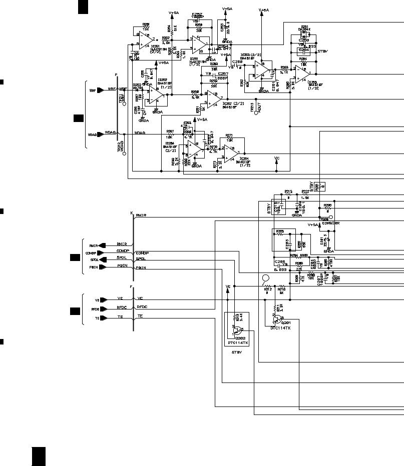
|
1 |
|
2 |
|
3 |
|
4 |
|
|
|
|
|
|
PDR-W839
3.5 CD-R CORE ASSY(3/5)
A
A 3/5
CD-R CORE ASSY (PYY1286) 
A 2/5
B
|
A 5/5 |
C |
18 |
|
A 2/5 |
D
20 A 3/5
|
1 |
|
2 |
|
3 |
|
4 |
|
|
|
|
|
|
||||
|
|
|
|
|
|
5 |
|
6 |
|
7 |
|
8 |
|
|
|
|
|
|
PDR-W839
A
A 4/5
A 1/5
A 2/5
Multiplexer
B
A 1/5
C
Servo Amp IC
D
A 3/5 21
|
5 |
|
6 |
|
7 |
|
8 |
|
|
|
|
|
|
||||
|
|
|
|
|
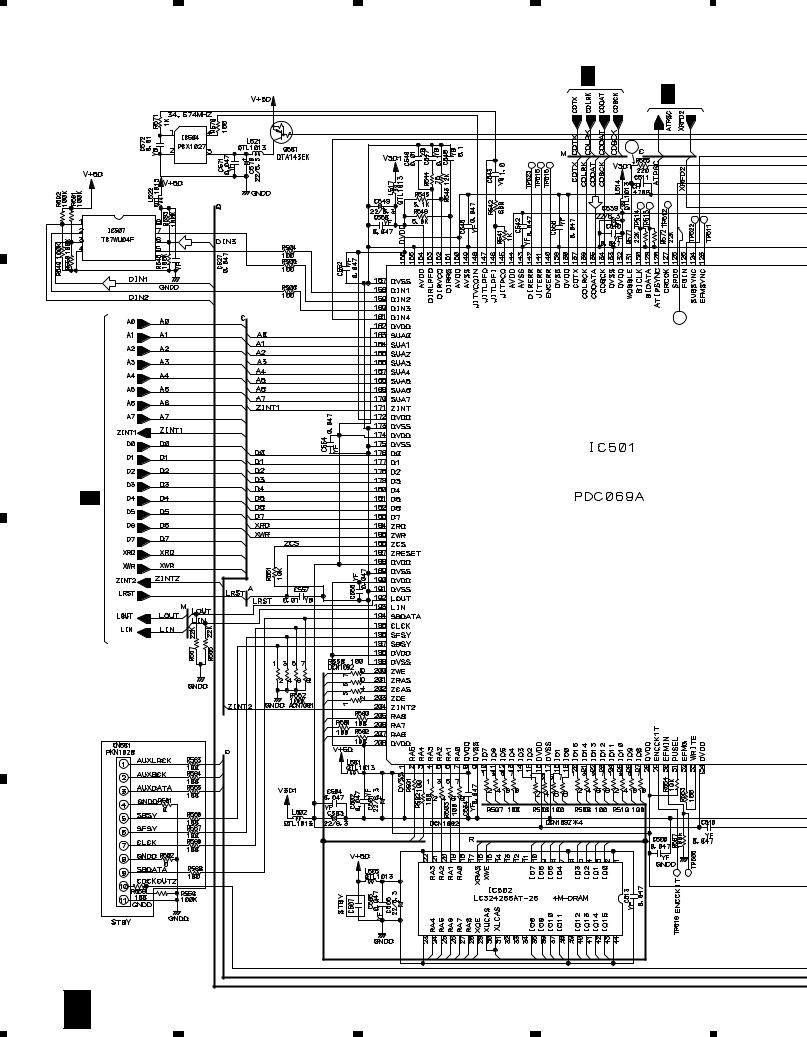
|
1 |
2 |
3 |
4 |
PDR-W839 |
|
|
|
|
3.6 CD-R CORE ASSY(4/5) |
|
A 5/5 |
||
|
|
|
|
A 1/5 |
A |
|
|
|
|
|
|
|
|
24 |
|
|
(CO) |
|
|
|
(OP) |
|
|
|
|
|
|
|
23 |
B |
|
|
|
|
|
A 1/5 |
|
|
EFM ENCODER |
|
|
|
|
|
C |
|
|
|
|
D |
|
|
|
|
22 |
A 4/5 |
|
|
|
|
1 |
2 |
3 |
4 |
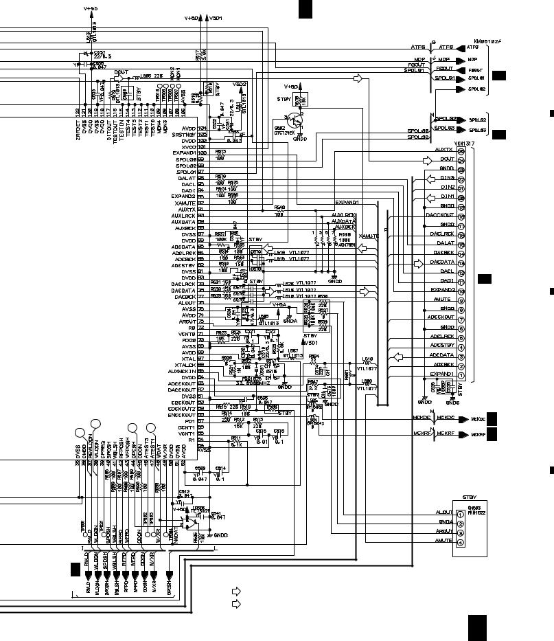
|
5 |
|
6 |
|
7 |
|
8 |
|
|
|
|
|
|
PDR-W839
A 4/5
CD-R CORE ASSY (PYY1286)
A
|
|
|
|
|
|
3/5 |
|
(D) |
|
|
(D) |
|
A |
|
|
|
|
|
CN502 |
A 5/5 |
|
|
|
|
|
|
|
|
|
|
|
(D) |
|
|
|
|
|
|
|
(CO) |
|
|
|
|
|
|
(OP) |
|
|
|
|
|
|
|
B |
|
|
|
(R) |
(D) |
|
2/3CN601 |
|
|
|
(R) |
|
|
|
|
|
|
|
|
|
H |
|
|
|
(D) |
(D) |
|
|
|
|
|
|
|
|
|
|
|
|
|
(R) |
|
|
|
|
|
|
|
|
C |
20 |
21 |
22 |
|
|
|
A 5/5 |
19 |
|
|
|
A 2/5 |
||
|
|
|
|
|
||
|
|
|
|
|
|
|
A |
|
|
|
|
|
D |
|
SIGNAL ROUTE |
|
|
|
||
2/5 |
|
|
|
|
||
|
(R) |
: AUDIO SIGNAL (REC) |
|
|
|
|
|
|
|
|
|
|
|
(D)
: AUDIO SIGNAL (DIGITAL)
A 4/5 23
|
5 |
|
6 |
|
7 |
|
8 |
|
|
|
|
|
|
||||
|
|
|
|
|
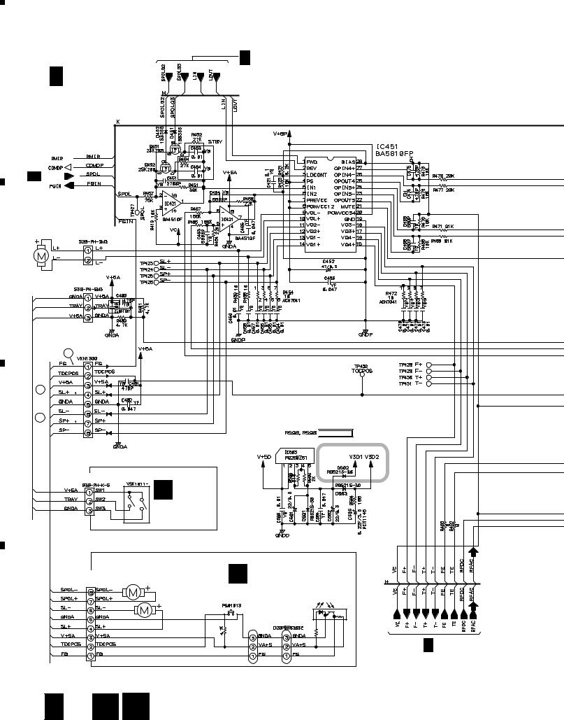
A
B
C
D
1 |
|
2 |
|
3 |
|
4 |
|
|
|
|
|
PDR-W839
3.7 CD-R CORE ASSY(5/5),MECHA PCB ASSY and LOAB ASSY
A 4/5
A 5/5
CD-R CORE ASSY
(PYY1286)
5CH BTL Driver
3/5A

LOADING MOTOR
PXM1017
CN453
VKP2253
CN451
27 CN452
25
26

 F Rank (1%)
CN101 S101
B
LOAB ASSY
(VWG2171)
CN601 |
DC MOTOR ASSY |
MECHA PCB ASSY |
|
(SPINDLE) |
C (PWX1625) |
|
|
08FM-1.0ST |
PXM1044 |
|
|
|
S601 |
|
|
|
CARRIAGE MOTOR |
|
|
|
ASSY (SLIDER) |
PC651 |
|
|
PEA1359 |
|
|
|
NJL5803K-F1 |
|
|
|
R602 |
J601 |
R651 |
|
240 |
||
|
|
|
A 2/5 |
24 A 5/5 B 
 C
C
|
1 |
|
2 |
|
3 |
|
4 |
|
|
|
|
|
|
||||
|
|
|
|
|
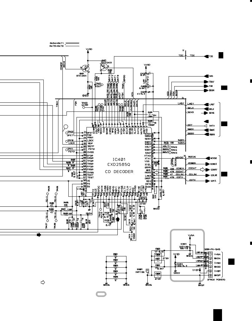
|
5 |
|
6 |
|
7 |
|
8 |
|
|
|
|
PDR-W839

 F rank (1%)

A 2/5
 A 1/5
A 1/5


 1/5A 28

(D) |
A4/5 |
|
(D) |
A
B
SIGNAL ROUTE  : RF SIGNAL
(D)
: AUDIO SIGNAL (DIGITAL)
C
CN901
(GND reinforcement for radiation measures)
M
CN202
D
: The power supply is shown with the marked box.
A 5/5 25
|
5 |
|
6 |
|
7 |
|
8 |
|
|
|
|
|
|
||||
|
|
|
|
|
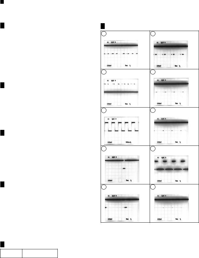
PDR-W839
VOLTAGES and WAVEFORMS
 Signal Logic
• Spindle System
A 4/5 CD-R CORE ASSY
Media |
Pickup Position |
SPLG1 |
SPLG3 |
|
(IC501-pin97) |
(IC501-pin99) |
|||
|
|
|||
|
|
|
|
|
CD |
Inner |
5V |
0V |
|
|
|
|
||
Outer |
0V |
5V |
||
|
||||
|
|
|
|
|
|
12cm Inner |
5V |
0V |
|
CD-R |
|
|
|
|
12cm Outer |
0V |
5V |
||
CD-RW |
||||
|
|
|
||
8cm CD-R |
0V |
5V |
||
|
||||
|
|
|
|
|
|
STOP |
5V |
5V |
|
|
|
|
|
*Inner: Absolute time is less than 23 minutes. Outer: Absolute time is more than 23 minutes.
A 1/5 CD-R CORE ASSY
Operating |
CLV |
ECLV |
Mode |
(IC301-pin 30) |
(IC301-pin 29) |
|
|
|
STOP |
0V |
0V |
|
|
|
CAV, W-CLV |
5V |
0V |
|
|
|
E-CLV |
5V |
5V |
|
|
|
*W-CLV: WOBBLECLV , E-CLV: EFMCLV
•Digital Input System
A 4/5 CD-R CORE ASSY
|
at FS = 44.1 kHz |
Others |
|
|
|
|
|
XVCO |
0V |
5V |
|
(IC501-pin 101) |
|||
|
|
||
|
|
|
|
|
|
|
|
|
at DIGITAL LOCK |
at DIGITAL UNLOCK |
|
|
|
|
|
DIRERR |
0V |
5V |
|
(IC501-pin 142) |
|||
|
|
||
|
|
|
• Audio System
A 4/5 CD-R CORE ASSY
|
A/D Converter used |
||
|
|
|
|
|
at Analog REC Pause, |
Others |
|
|
REC, Monitor |
||
|
|
||
ADCSTBY |
5V |
0V |
|
(CN502-pin 4) |
|||
|
|
||
|
|
|
|
|
at MUTE ON |
at MUTE OFF |
|
|
(Audio Signal Not Output) |
(Audio Signal Output) |
|
|
|
|
|
AMUTE |
5V |
0V |
|
(CN502-pin 9) |
|||
|
|
||
|
|
|
• Others |
|
|
A 1/5 CD-R CORE ASSY |
||
XPFAIL |
5V |
|
(CN302-pin 9) |
||
|
||
Note :
The encircled numbers denote measuring point in the schematic diagram.
A 1/5 CD-R CORE ASSY
1 |
CN302 - pin 1 (MSI) |
6 |
IC301 - pin 21 (CLOCKDEC) |
|
V: 200mV/div. , H: 5msec/div. |
V: 200mV/div. , H: 5msec/div. |
|||
|
|
2 |
CN302 - pin 2 (MSO) |
7 |
IC301 - pin 24 (XLATDEC) |
|
V: 200mV/div. , H: 5msec/div. |
V: 200mV/div. , H: 5msec/div. |
|||
|
|
3 |
CN302 - pin 5 (MSCK) |
8 |
IC301 - pin 25 (CLOCKRF) |
|
V: 200mV/div. , H: 500nsec/div. |
V: 200mV/div. H: 5msec/div. |
|||
|
|
|||
|
(PLAY) |
|
|
4 |
CN302 - pin 7 (SYSREQ) |
9 |
IC301 - pin 26 (DATA) |
|
V: 200mV/div. , H: 5msec/div. |
V: 200mV/div. , H: 5msec/div. |
|||
|
|
5 |
CN302 - pin 8 (MACK) |
10 |
IC301 - pin 27 (XLATRF) |
|
V: 200mV/div. , H: 5msec/div. |
|
V: 200mV/div. , H: 5msec/div. |
26
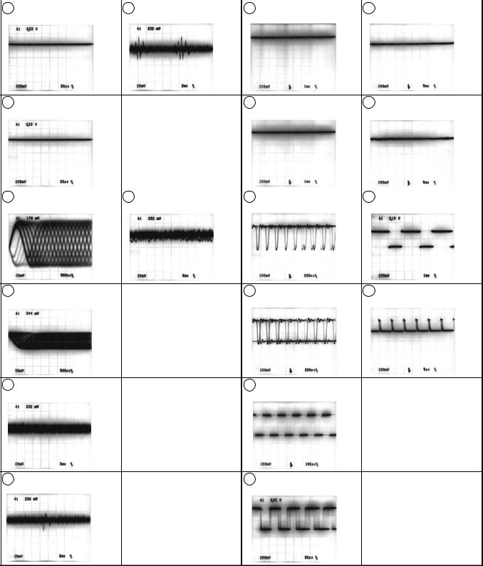
PDR-W839
A |
2/5 CD-R CORE ASSY |
|
|
A |
4/5 CD-R CORE ASSY |
A |
5/5 CD-R CORE ASSY |
|||
|
|
|
|
|
|
|
|
|
|
|
11 |
CN101 - pin 29 (F+) |
17 |
CN102-pin 8 (FE) |
19 |
IC501 - pin 37 (REWLDON) |
25 |
CN452 - pin 4 (SL+) |
|||
|
|
V: 200mV/div. , H: 20μsec/div. |
|
V: 20mV/div. , H: 2msec/div. |
|
|
V: 200mV/div. , H: 1msec/div. |
|
|
V: 200mV/div. , H: 5msec/div. |
|
|
|
|
(PLAY) |
|
|
(REC) RW |
|
|
(PLAY) |
12 |
CN101 - pin 30 (T+) |
20 |
IC501 - pin 38 (WLDON) |
26 |
CN452 - pin 7 (SP+) |
|
V: 200mV/div. , H: 20μsec/div. |
|
V: 200mV/div. , H: 1msec/div. |
|
V: 200mV/div. , H: 5msec/div. |
|
|
|
(REC) |
|
(PLAY) |
|
|
|
A |
3/5 CD-R CORE ASSY |
|
|
|
|
|
|
|
|
|
|
|
|
|
13 |
CN102 - pin 1 (EQRF) |
18 |
Foot of R212 (SPDL) |
21 |
IC501 - pin 45 (ODON) |
27 |
CN452 - pin 1 (FG) |
|
|
V: 20mV/div. , H: 500nsec/div. |
|
|
V: 20mV/div. , H: 2msec/div. |
|
V: 200mV/div. , H: 200nsec/div. |
|
V: 200mV/div. , H: 1msec/div. |
|
(PLAY) |
|
|
(PLAY) |
|
(REC) |
|
(PLAY) |
14 |
CN102 - pin 2 (RF) |
22 |
IC501 - pin 48 (WDAT) |
28 |
IC401 - pin 25 (MDP) |
|
V: 50mV/div. , H: 500nsec/div. |
|
V: 200mV/div. , H: 200nsec/div. |
|
V: 200mV/div. , H: 5μsec/div. |
|
(PLAY) |
|
(REC) |
|
(PLAY) |
15 |
CN102 - pin 4 (MPP) |
23 |
IC501 - pin 126 (SPDO) |
|
V: 20mV/div. , H: 2msec/div. |
|
V: 200mV/div. , H: 100μsec/div. |
|
(PLAY) |
|
(REC) |
16 |
CN102 - pin 5 (TE) |
24 |
Foot of R583 (ATFG) |
|
V: 20mV/div. , H: 2msec/div. |
|
V: 200mV/div. , H: 20μsec/div. |
|
(PLAY) |
|
(REC) |
27
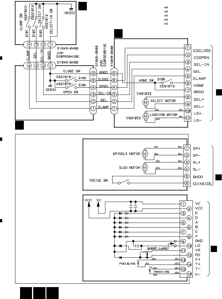
|
1 |
|
2 |
|
3 |
|
4 |
|
|
|
|
|
|
PDR-W839
3.8 MOTOR, LOADING, SELECT and PICKUP UNITS
A
J101
J101
B
G SELECT UNIT |
(T) |
: FOCUS SERVO LOOP LINE |
|
(F) |
|
(AWU7433) |
(S) |
: TRACKING SERVO LOOP LINE |
: SPINDLE SERVO LOOP LINE |
||
|
(C) |
: CARRIAGE SERVO LOOP LINE |
|
(L) |
: LOADING SERVO LOOP LINE |
E MOTOR UNIT (AWU7431)
CN101
S11B-PH-K-S
D CN1302
|
(L) |
(L) |
J102 |
J102 |
(L) |
|
||
F LOADING UNIT (AWU7432) |
(L) |
|
|
|
|
PICKUP UNIT |
|
|
(KSM213CCM) |
(S) |
(S) |
|
(S) |
(S) |
|
(C) |
(C) |
|
(C) |
(C) |
CN1301
C
D
D
D CN1101
(F) |
(F) |
(T) |
(T) |
(T)(T)
(F)
(F)
28 E 
 F
F 
 G
G
|
1 |
|
2 |
|
3 |
|
4 |
|
|
|
|
|
|
||||
|
|
|
|
|
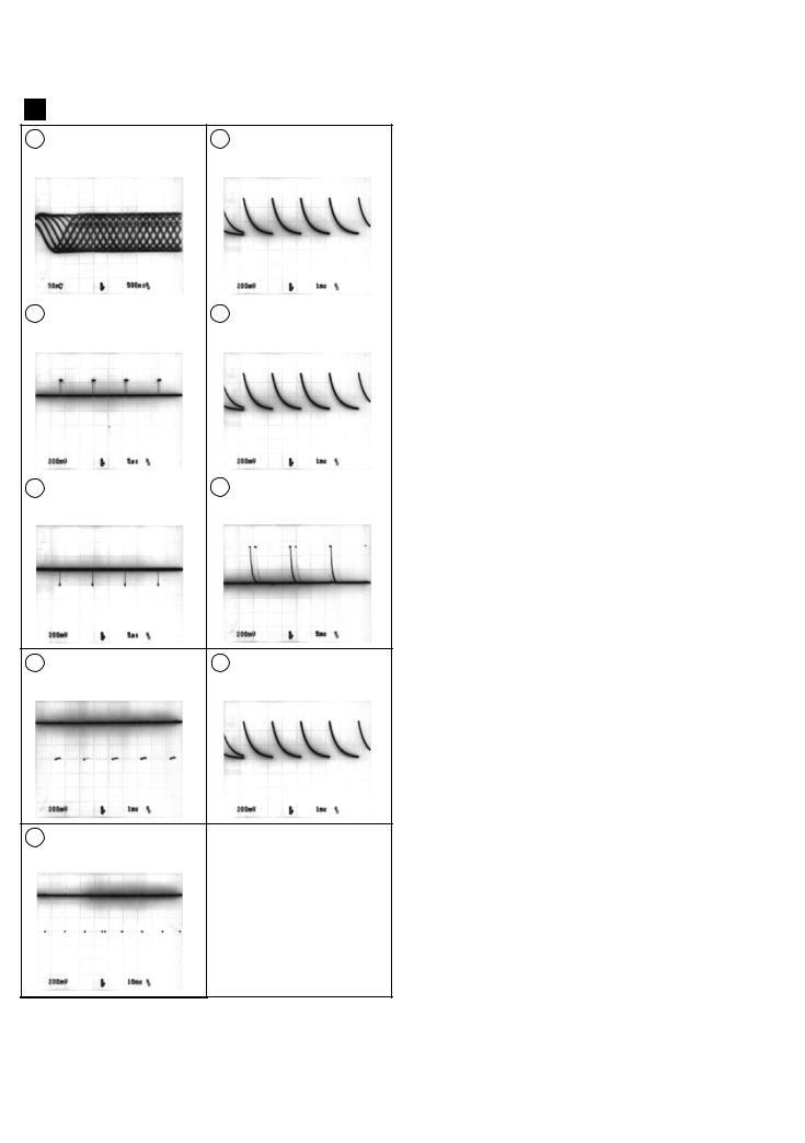
|
1 |
|
2 |
|
3 |
|
4 |
|
|
|
|
PDR-W839
D 3CD CORE ASSY
1 IC1101 - pin 25 (RFGO) |
5 CN1201 - pin 12 (BUS0) |
V: 50mV/div., H: 500nsec/div. |
V: 200mV/div., H: 1msec/div. |
(PLAY) |
(PLAY) |
2 -1 IC1201 - pin 55 (DMO) |
6 CN1201 - pin 13 (BUS1) |
V: 200mV/div., H: 5μsec/div. |
V: 200mV/div., H: 1msec/div. |
(PLAY) |
(PLAY) |
|
|
2 -2 IC1201 - pin 55 (DMO) |
7 CN1201 - pin 14 (BUS2) |
V: 200mV/div., H: 5μsec/div. |
V: 200mV/div., H: 5msec/div. |
(Hi-COPY) |
(PLAY) |
3 CN1201 - pin 10 (XCCE) |
8 CN1201 - pin 15 (BUS3) |
V: 200mV/div., H: 1msec/div. |
V: 200mV/div., H: 1msec/div. |
(PLAY) |
(PLAY) |
4CN1201 - pin 11 (BUCK)
V: 200mV/div., H: 10msec/div. (PLAY)
29
A
B
C
D
|
1 |
|
2 |
|
3 |
|
4 |
|
|
|
|
|
|
|
|||||
|
|
|
|
|
|||||
|
|
|
|
|
|
|
|
|
|

|
1 |
|
2 |
|
3 |
|
|
|
|
|
PDR-W839
3.9 3CD CORE ASSY
D 3CD CORE ASSY (PWM2334)
A
5CH BTL Driver
STBY
B
CN1302
E CN101
CN1301
C
UNIT |
CN1101 |
|
To PICKUP |
||
|
D
30 D
4
H : Normal Speed
L : Double Speed
1
|
1 |
|
2 |
|
3 |
|
4 |
|
|
|
|
|
|
||||
|
|
|
|
|
 Loading...