


F-208

FM/AM DIGITAL-SYNTHESIZER TUNER
FM/AM 數位石英振盪接收器
F-208
Operating Instructions
Manual de instruções
使用說明書

IMPORTANT
Y
CAUTION
RISK OF ELECTRIC SHOCK
DO NOT OPEN
The lightning flash with arrowhead symbol,
within an equilateral triangle, is intended to
alert the user to the presence of uninsulated
"dangerous voltage" within the product's
enclosure that may be of sufficient
magnitude to constitute a risk of electric
shock to persons.
CAUTION:
TO PREVENT THE RISK OF ELECTRIC
SHOCK, DO NOT REMOVE COVER (OR
BACK). NO USER-SERVICEABLE PARTS
INSIDE. REFER SERVICING TO QUALIFIED
SERVICE PERSONNEL.
Thank you for buying this Pioneer product.
Please read through these operating instructions so you
will know how to operate your unit properly. After you
have finished reading the instructions, keep them in a
safe place for future reference.
In some countries or regions, the shape of the power
plug and power outlet may sometimes differ from that
shown in the explanatory drawings. However, the method
of connecting and operating the unit is the same.
WARNING:
The apparatus is not waterproofs, to
prevent fire or shocks hazard, do not expose this
apparatus to rain or moisture and do not put any
water source near this apparatus, such as vase,
flower pot, cosmetics container and medicine
bottle etc.
D3-4-2-1-3_En
Voltage selector
ou can find the voltage selector switch on the rear
panel of multi-voltage models.
The factory setting for the voltage selector is 220 V.
Please set it to the correct voltage for your country
or region.
• For Taiwan, please set to 110 V before using.
WARNING:
BEFORE PLUGGING IN THE UNIT FOR THE FIRST
TIME, READ THE FOLLOWING SECTION CAREFULLY.
The voltage of the available power supply differs
according to country or region. Be sure that the
power supply voltage of the area where this unit
will be used meets the required voltage (e.g., 230V
or 120V) written on the rear panel.
WARNING:
lighted candle, should be placed on the apparatus.
If naked flame sources accidentally fall down, fire
spread over the apparatus then may cause fire.
WARNING: Slot and openings in the cabinet are
provided for ventilation and to ensure reliable
operation of the product and to protect it from
overheating, to prevent fire hazard, the openings
should never be blocked and covered with items,
such as newspapers, table-cloths, curtains, etc. Also
do not put the apparatus on the thick carpet, bed,
sofa, or fabric having a thick pile.
The exclamation point within an equilateral
triangle is intended to alert the user to the
presence of important operating and
maintenance (servicing) instructions in the
literature accompanying the appliance.
D3-4-2-1-1_En
D3-4-2-1-4_En
No naked flame sources, such as
D3-4-2-1-7a_En
D3-4-2-1-7b_En
Before changing the voltage, disconnect the AC power
cord. Use a medium size screwdriver to change the
voltage selector switch.
Operating Environment
Operating environment temperature and humidity:
+5 ºC – +35 ºC (+41 ºF – +95 ºF); less than 85 %RH
(cooling vents not blocked)
Do not install in the following locations
• Location exposed to direct sunlight or strong artificial
light
• Location exposed to high humidity, or poorly
ventilated location
D3-4-2-1-7c_En
Medium-size screwdriver
D3-4-2-1-5_En
This product is for general household purposes. Any
failure due to use for other than household purposes
(such as long-term use for business purposes in a
restaurant or use in a car or ship) and which
requires repair will be charged for even during the
warranty period.
K041_En
2
En
CAUTION
The POWER switch does not completely separates
the unit from the MAINS in off position. Therefore
install the unit suitable places easy to disconnect
the MAINS plug in case of the accident. The MAINS
plug of unit should be unplugged from the wall
socket when left unused for a long period of time.
D3-4-2-2-2b_En

CONTENTS
FEATURES ............................................. 3
CHECKING THE ACCESSORIES ........... 3
INSTALLATION ...................................... 4
CONNECTIONS...................................... 5
ANTENNA CONNECTIONS ...................... 6
FRONT PANEL FACILITIES ................... 7
BASIC TUNING OPERATIONS ............ 10
AUTO AND MANUAL TUNING..............10
DIRECT ACCESS TUNING ..................... 11
FEATURES
7 RF ATT
A built-in attenuator (RF ATT) can be switched on or
off for proper reception of strong boradcast stations.
7 Random 30-station presetting
A total of 30 FM and AM stations can be preset into
the memory circuit.
7 Manual station name memory
Using up to 4 characters, you can store a name of
your choice for preset FM/AM broadcast stations 1
to 30.
PRESETTING STATIONS ..................... 12
PRESET STATIONS ................................ 12
PRESET STATION TUNING ................... 13
MEMORY SCAN ..................................... 13
MANUAL STATION NAME MEMORY ..... 14
TROUBLESHOOTING .......................... 16
SPECIFICATIONS ................................. 17
7 Memory scan
This function receives preset stations within a class
(A, B or C) in order, letting you select a desired station while checking what program the station is broadcasting.
7 Energy-saving design
This unit is designed to use minimal electricity when
power is switched OFF (during Standby).
Regarding the value of the power consumption in
standby mode, refer to “SPECIFICATIONS” on page
17.
CHECKING THE ACCESSORIES
AM loop antenna
FM T-type antenna
Audio cord
Control cord
3
En

INSTALLATION
CHANNEL STEP SETTING
Before using the unit for the first time, be sure to set the
correct channel step (FM and AM) for your area.
If the channel step setting is incorrect, tuning to the correct frequency will not be possible, and poor sound quality due to distortion and noise will prevent reproduction
of the received signal.
FM 100 kHz, AM 10 kHz:
Set to this position for areas with an FM reception step
of 100 kHz and AM 10 kHz.
FM 50 kHz, AM 9 kHz:
Set to this position, for areas with an FM reception step
of 50 kHz and AM 9 kHz.
NOTE:
When unsure about the channel allocation for your area,
consult your dealer for correct information.
To change channel steps
Setting the FM channel step to 100kHz and the AM
channel step to 10kHz:
When power is in standby, press the STANDBY/ON
switch while pressing STATION CALL button 0/10 to
switch power ON.
Setting the FM channel step to 50kHz and the AM
channel step to 9kHz:
When power is in standby, press the STANDBY/ON
switch while pressing STATION CALL button 9 to
switch power ON.
LOCATION
Install the tuner in a well-ventilated location
where it will not be exposed to high
temperatures or humidity.
Do not install the tuner in a location which is exposed to
direct rays of the sun, or near hot appliances or radiators.
Excessive heat can adversely affect the cabinet and internal components. Installation of the tuner in a damp or
dusty environment may result in a malfunction or accident. (Also avoid installation near cookers, etc., where
the tuner may be exposed to smoke, steam, or heat.)
CONDENSATION
When this unit is brought into a warm room from previously cold surroundings or when the room temperature
rises sharply,condensation may from inside,and the unit
may not be able to attain its full performance. In this case,
allow the unit to stand for about an hour or raise the room
temperature gradually.
POWER-CORD CAUTION
Handle the power cord by the plug. Do not pull out the
plug by tugging the cord and never touch the power cord
when your hands are wet as this could cause a short circuit or electric shock. Do not place the unit, a piece of
furniture, etc., on the power cord, or pinch the cord. Never
make a knot in the cord or tie it with other cords. The
power cords should be routed such that they are not likely
to be stepped on. A damaged power cord can cause fire
or give you an electrical shock. Check the power cord
once in a while. When you find it damaged, ask your nearest PIONEER authorized service center or your dealer for
a replacement.
4
En
Maintenance of external surfaces
¶ Use a polishing cloth or dry cloth to wipe off dust
and dirt.
¶ When the surfaces are very dirty, wipe with a soft
cloth dipped in some neutral cleanser diluted five
or six times with water, and wrung out well, and
then wipe again with a dry cloth. Do not use furniture wax or cleaners.
¶ Never use thinners, benzine, insecticide sprays or
other chemicals on or near this unit, since these
will corrode the surfaces.

CONNECTIONS
Before making or changing the connections, switch off
the power switch and disconnect the power cord from
the AC outlet.
Accessory FM T-type antenna
Stereo amplifier
Outdoor FM
antenna
ANTENNA
FM
UNBAL
75Ω
AM
LOOP
ANTENNA
Connecting the FM T-type antenna
and AM loop antenna
15 mm
1. Strip and twist the ends of the wires.
2. With tabs beneath connector down, insert
wires from antenna.
Accessory AM loop antenna
CONTROL
OUTPUT
L
R
IN
OUT
CONTROL terminals
Pin plug connecting cord
¶ Connect the white plug to the white terminal (L) and
the red plug to the red terminal (R).
¶ Make sure that the connections are secure.
Accessory
Audio cord
110 - 127V
220 - 240V
Left channel
GND
INPUT
PHONO CD TUNER
TWO VOLTAGE SERECTORS
110V
120 - 127V
240V
220V
Plug the power cord
into an ACwall socket.
White plug
L
R
CONTROL terminals
When using together with a Pioneer component bearing the Î mark, connect the CONTROL IN terminal on
the rear panel of the tuner to the CONTROL OUT terminal on the component using the supplied control cord.
This will enable the tuner to be controlled from a distance with the remote control unit supplied with the
component.
When this feature is not used, connection is not necessary.
¶ For instructions regarding connection and operation,
please refer to the operating instructions of your stereo component.
Stereo
Amplifier
IN OUT
Cassette Deck
CONTROL
IN OUT
CONTROL
IN
OUT
F-208
CONTROL
OUT
CD Player
CONTROL
IN
Red plug
Right channel
Antenna ground
ANTENNA
FM
UNBAL
75Ω
AM
LOOP
ANTENNA
NOTE:
The (signal earth) helps reduce noise when an antenna
is connected. It is not a safety earth.
CAUTION:
Never make the ground connection to a gas pipe as sparks
can cause the gas ignite.
5
En
CONNECTIONS
ANTENNA CONNECTIONS
Radio reception is not possible unless the
antenna is properly connected.
The strength of broadcast signals varies from one area to
another. Signal propagation is especially poor in metropolitan areas, where there are many tall buildings, and
also in mountainous areas. Proper antenna installation is
vital to good reception.
AM ANTENNA
The AM loop antenna supplied with the tuner should be
connected to the AM antenna terminals. The antenna
should be placed at a distance from the tuner, and should
not be allowed to touch metallic objects. Avoid placing it
near CD players, personal computers, television sets, and
other devices generating radio frequencies.
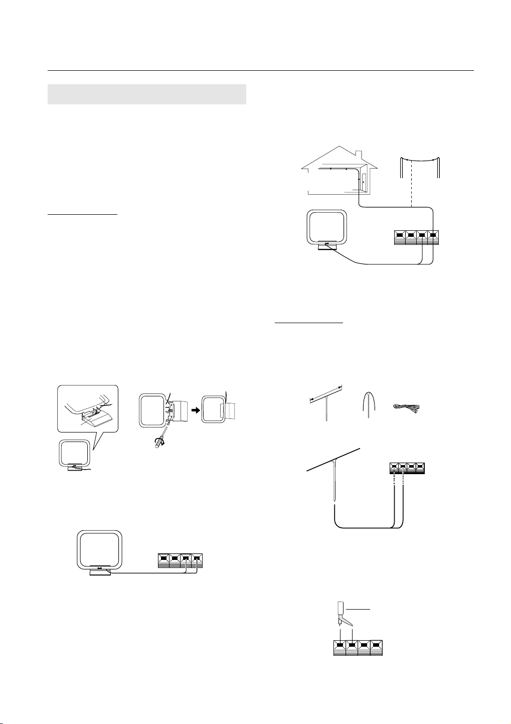
Setting up the AM loop antenna
¶ Insert the clip on the bottom of the antenna into the
groove on the leg.
¶ Place the antenna on a level surface and rotate it to
locate the orientation that yields the best reception.
¶ To permanently affix the antenna,screw the leg to a
wall or post before assembling (affixing the antenna in
the direction that gives the best reception).
Lead wire
Outdoor AM antenna
If reception is still poor even when a lead antenna has
been stretched out indoors, stretch out a vinyl-coated wire
and secure it outdoors.
Connecting the external AM antenna
Outdoor AM antenna
Indoor AM antenna
AM loop antenna
NOTE:
Do not detach the AM loop antenna when using an external AM antenna.
FM ANTENNA
FM T-type antenna attachment
Connect the accessory FM T-type antenna to the FM terminals. Stretch the antenna out to its full length, and affix
it to a wall, etc. The accessory FM T-type antenna must
be connected to ensure proper reception.
Leg
AM Loop Antenna Connection
The accessory AM loop antenna must be connected to
ensure proper reception.
External AM antenna
Indoor AM antenna
Provide a vinyl-coated wire (5 to 6 meters long). Secure
one end to the AM terminal marked “AM LOOP ANTENNA” and the other end to a wall or other high location.
6
En
Correct Wrong Wrong
Outdoor external FM antenna installation
Use an external antenna when the signals from the station are weak and cannot be picked up by the accessory
T-type FM antenna, or when the sound heard is accompanied by too much noise.
75 Ω coaxial cable
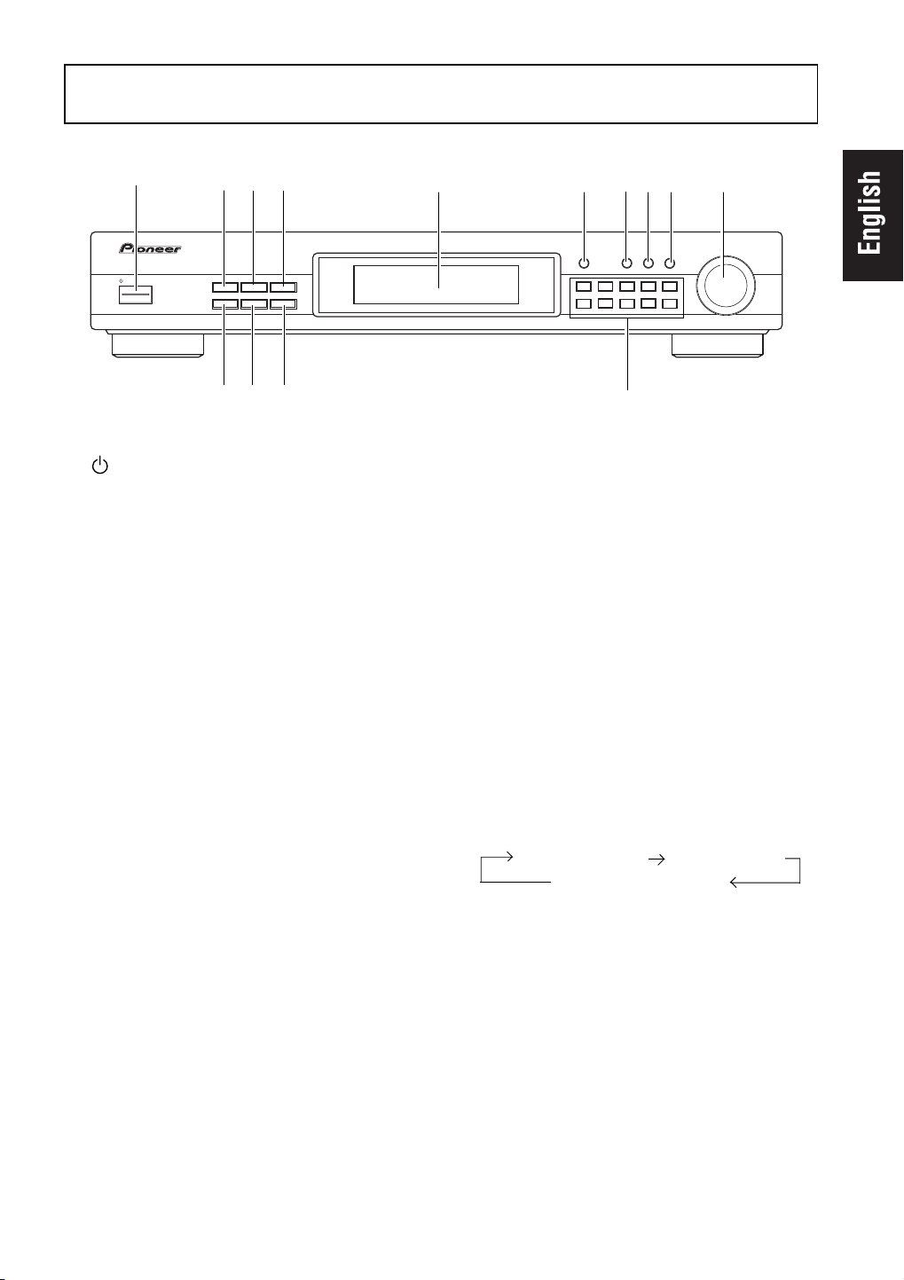
FRONT PANEL FACILITIES
1
FM/
AM DIGITAL-SYNTHESIZER TUNER
STANDBY/ON
234
Î
X¿<?˘
CHARACTER
MPX
MODE
=
DISPLAY
MODE
BAND
~
MEMORY
SCAN
RF ATT
-
1 STANDBY/ON switch
This is the switch for electric power.
ON .................. When set to ON position, power is
supplied and the unit becomes
operational.
STANDBY ....... When set to STANDBY position, the main
power flow is cut and the unit is no longer
fully operational. A minute flow of power
feeds the unit to maintain operation
readiness.
NOTES:
The memory will be backed up so long as the power
cord is unplugged.
If the power cord is unplugged, the memory will be
retained for several days.
When not using the unit for a long period, disconnect
the power cord.
2 MEMORY SCAN button
When this button is pressed, preset stations within a class
(A, B or C) are received in order. (See page 13)
3 CHARACTER button
You can use it to input station names manually. (see page
14)
4 DISPLAY MODE button
When in the Preset Station Selection mode, pressing this
button changes display indications. If no station names
are memorized, this button has no function.
When no station name is memorized,the DISPLAY MODE
button becomes invalid.
5 6
789 0
MEMORY
12345
6
DIRECT
CLASS
789
TUNING
TUNING
MODE
0/10
!
6 MEMORY button
Use to preset stations. This is also used for FM or AM
broadcast manual station name character selection.
7 CLASS button
Use to switch between preset memory classes A to C.
In each class, 10 stations can be memorized using the
STATION CALL buttons, enabling a total of 30 stations to
be memorized.
8 DIRECT button
When this button is pressed, the STATION CALL buttons
function as ten-key number buttons for direct input of
the desired reception frequency. Press again to cancel
this mode.
9 TUNING MODE button
Each time you press this button, the TUNING knob's
function changes as follows.
Manual tuning mode
Preset station tuning mode
0 TUNING knob
Use for tuning. To raise the frequency, turn in a
clockwise direction; to lower the frequency, turn
counterclockwise. In the Station Name input mode,
the TUNING knob is used to select characters. When
presetting a station or selecting a preset station, you
can also turn this knob to select a desired station
number.
Auto tuning mode
5 Operating display
7
En

FRONT PANEL FACILITIES
- RF ATT button
Set this button to on when receiving strong FM signals
(nearby stations) to reduce sound distortion (RF ATT
indicator lights).
Normally, this button should be set to off.
This button does not affect AM reception.
NOTE:
This button’s status is preset for each station in station
memory.
= MPX (multiplex) MODE button
Mode changes as follows each time this button is
pressed.
AUTO MONO
This button does not affect AM reception.
AUTO:
“AUTO”is not displayed.
Normally leave in this mode for reception. When a stereo
FM broadcast is received, it will be automatically
reproduced in stereo sound and the STEREO indicator
lights up.
MONO:
MONO indicator lights up.
To receive stereo broadcasts in monaural.
If there is too much noise during stereo reception of a
weak signal, you can reduce the level of noise by
switching to MONO.
NOTES:
This button’s status is preset for each station in station
memory.
When the signal level is too weak for reception, sound
output is automatically muted. If sound is muted when
the selected mode is AUTO, switching to MONO lets
you hear the broadcast.
~ BAND button
The button is used to select either FM or AM reception.
! STATION CALL buttons
Use these buttons to preset stations and to receive the
already preset stations.
These are also used when performing direct access
tuning.
8
En

Operating display
FRONT PANEL FACILITIES
1
MEMORY
AUTO
2
1 MEMORY indicator
Lights when presetting stations.
2 AUTO indicator
Lights during auto tuning mode.
3
Frequency and character display section
Band and frequency data is displayed.
4 RF ATT indicator
Stays lit while RF ATT button is on.
3
4
STEREO
TUNED
6
RF ATT
MONO
5
7
5 MONO indicator
Stays lit while MPX MODE button is set to MONO.
6 STEREO indicator
Lights up when a stereo broadcast is received (the
indicator does not light when the MPX MODE button is
set to MONO).
7 TUNED indicator
Lights when a broadcast is received.
En
9

BASIC TUNING OPERATIONS
The following steps show you how to tune in FM and
AM radio broadcasts using “Auto and Manual Tuning”. If
you already know the exact frequency of the station you
want, see “Direct Access Tuning” on the following page.
AUTO AND MANUAL TUNING
MPX MODE
1
RF ATT
2
3
3
1. Turn the STANDBY/ON switch ON.
2. Press the desired BAND button.
3. Tuning into the frequency of a desired
station.
Press the TUNING MODE button to select the tuning mode.
Each time you press this button, the tuning mode
changes as follows.
Manual tuning mode Auto tuning mode
Preset station tuning mode
[Manual tuning mode]
To raise the frequency, turn clockwise; to lower the frequency, turn counterclockwise.
[Auto tuning mode]
To tune into a frequency higher than the one indicated,
turn the TUNING knob clockwise. To tune into a frequency
lower than the one indicated, turn the TUNING knob counterclockwise; release when the frequency indication starts
changing. The frequency display changes, and tuning
automatically stops when a frequency that can be received
is found.To search for another station, turn the TUNING
knob once more.
NOTES:
(On auto tuning)
Because of the high sensitivity of this unit, it may automatically stop even at very weak overseas stations.
The same can happen with aggregate radio noise emitted in cities.
During reception of an AM broadcast, auto tuning of
only strong local stations is possible by changing the
direction of the loop antenna or folding it down. After
tuning, move the loop antenna back to its previous
position.
Tune extremely weak stations with manual tuning.
If the radio waves of available stereo stations are
weaker than a certain level,the auto-tuning may not
function for these stations.
(When receiving FM broadcasts)
If there is distortion because the radio signal is too
strong, press the RF attenuator (RF ATT) button to light
the RF ATT indicator.
If there is too much noise during reception of an FM
stereo broadcast, press the MPX MODE button to light
the MONO indicator. Switching to monaural reception
results in clearer reception.
Tune into desired frequency with the TUNING knob.
¶ During auto tuning, the AUTO indicator in the
display lights. No indicator lights during manual
tuning. During preset station tuning, the station
number or station name is displayed.
4. To receive another station in the same
band, repeat step 3. To receive a station
in the other band, repeat steps 2 and 3.
5. Adjust the volume and tone of the
stereo amplifier.
10
En
The TUNED indicator
When the TUNED indicator is not lit, reception is not possible even if the tuning frequency is correct. This is because the antenna terminal input is too weak. Check
whether the antenna cable is firmly connected. If it is,
consult your nearest dealer and install an outdoor antenna.
Last station memory
¶ When the STANDBY/ON switch is pressed to turn
the power on, the last station received before the power
was turned off will be received again.
¶ When the power is ON and the BAND button is
pressed, the last station received on that band will be
received again.

BASIC TUNING OPERATIONS
DIRECT ACCESS TUNING
When you know the frequency of the desired station,
the frequency can be input directly using the STATION
CALL buttons in the following way.
1
2
3
4
1. Turn the STANDBY/ON switch ON.
2. Select the desired band with the BAND
button.
3. Press the DIRECT button.
4. Input the desired station frequency
using the STATION CALL buttons.
<Example> To receive FM 106.00 MHz.
1 Press the DIRECT button.
2 Press 1
3 Press 0/10
4 Press 6
5 Press 0/10
6 Press 0/10
DIRECT
1
2
1
3
0/10
4
6
5
0/10
To cancel frequency input
Direct access is canceled when the DIRECT button is
pressed again.
Under the following conditions, direct access is canceled
and the unit returns to the condition in effect before direct access was selected:
1 If there is no key input for approximately five seconds
after the DIRECT button is pressed.
2 If more than approximately five seconds elapse be-
tween number inputs.
NOTES:
Always input the frequency to the last digit.
After performing DIRECT ACCESS and inputting the
frequency, any discrepancy is corrected (for example,
FM 100.01 MHz = FM 100.00 MHz), so the MEMORY
button does not immediately function after the final
digit has been input. To memorize a station frequency,
first confirm that “MEMORY” is lit on the display before pressing the STATION CALL button.
6
0/10
STEREO
TUNED
11
En
 Loading...