


DV-737
ORDER NO.
PIONEER CORPORATION 4-1, Meguro 1-chome, Meguro-ku, Tokyo 153-8654, Japan
PIONEER ELECTRONICS SERVICE, INC. P.O. Box 1760, Long Beach, CA 90801-1760, U.S.A.
PIONEER EUROPE NV Haven 1087, Keetberglaan 1, 9120 Melsele, Belgium
PIONEER ELECTRONICS ASIACENTRE PTE. LTD. 253 Alexandra Road, #04-01, Singapore 159936
PIONEER CORPORATION 2000
c
Type
Model
Power Requirement Region No. Remarks
DV-37 DV-S77 DV-S737 DV-737 DV-737-K
KU/CA – – – – AC120V 1
LB – – – – AC110V 3
RL – – – – AC110-127V/220-240V 3
RL/RD – – – – AC110-127V/220-240V 4
WY – – – AC220-240V 2
DV-37
RRV2320
T – IZE AUG. 2000 Printed in Japan
DV-S77
THIS MANUAL IS APPLICABLE TO THE FOLLOWING MODEL(S) AND TYPE(S).
DVD PLAYER
DV-S737
DV-737
DV-737-K
1. SAFETY INFORMATION
.......................................
2
2. EXPLODED VIEWS AND PARTS LIST
.................
4
3. BLOCK DIAGRAM AND SCHEMATIC DIAGRAM
...
12
4. PCB CONNECTION DIAGRAM
...........................
39
5. PCB PARTS LIST
................................................
52
6. ADJUSTMENT
.....................................................
58
CONTENTS
7. GENERAL INFORMATION
................................
61
7.1 DIAGNOSIS
..................................................
61
7.1.1 TEST POINTS LOCATION
...................
61
7.1.2 TEST MODE SCREEN DISPLAY
........
62
7.1.3 TROUBLE SHOOTING
........................
64
7.1.4 ERROR CODE
.....................................
65
7.1.5 DISASSEMBLY
....................................
69
7.2 IC
..................................................................
70
8. PANEL FACILITIES AND SPECIFICATIONS
....
84
2
DV-37, DV-S77, DV-S737, DV-737, DV-737-K
1. SAFETY INFORMATION
This service manual is intended for qualified service technicians ; it is not meant for the casual do-it-
yourselfer. Qualified technicians have the necessary test equipment and tools, and have been trained
to properly and safely repair complex products such as those covered by this manual.
Improperly performed repairs can adversely affect the safety and reliability of the product and may
void the warranty. If you are not qualified to perform the repair of this product properly and safely, you
should not risk trying to do so and refer the repair to a qualified service technician.
WARNING
This product contains lead in solder and certain electrical parts contain chemicals which are known to the state of California to cause
cancer, birth defects or other reproductive harm.
Health & Safety Code Section 25249.6 – Proposition 65
NOTICE
(FOR CANADIAN MODEL ONLY)
Fuse symbols (fast operating fuse) and/or (slow operating fuse) on PCB indicate that replacement parts must
be of identical designation.
REMARQUE
(POUR MODÈLE CANADIEN SEULEMENT)
Les symboles de fusible (fusible de type rapide) et/ou (fusible de type lent) sur CCI indiquent que les pièces
de remplacement doivent avoir la même désignation.
ANY MEASUREMENTS NOT WITHIN THE LIMITS
OUTLINED ABOVE ARE INDICATIVE OF A POTENTIAL
SHOCK HAZARD AND MUST BE CORRECTED BEFORE
RETURNING THE APPLIANCE TO THE CUSTOMER.
2. PRODUCT SAFETY NOTICE
Many electrical and mechanical parts in the appliance
have special safety related characteristics. These are
often not evident from visual inspection nor the protection
afforded by them necessarily can be obtained by using
replacement components rated for voltage, wattage, etc.
Replacement parts which have these special safety
characteristics are identified in this Service Manual.
Electrical components having such features are identified
by marking with a
on the schematics and on the parts list
in this Service Manual.
The use of a substitute replacement component which does
not have the same safety characteristics as the PIONEER
recommended replacement one, shown in the parts list in
this Service Manual, may create shock, fire, or other hazards.
Product Safety is continuously under review and new
instructions are issued from time to time. For the latest
information, always consult the current PIONEER Service
Manual. A subscription to, or additional copies of, PIONEER
Service Manual may be obtained at a nominal charge from
PIONEER.
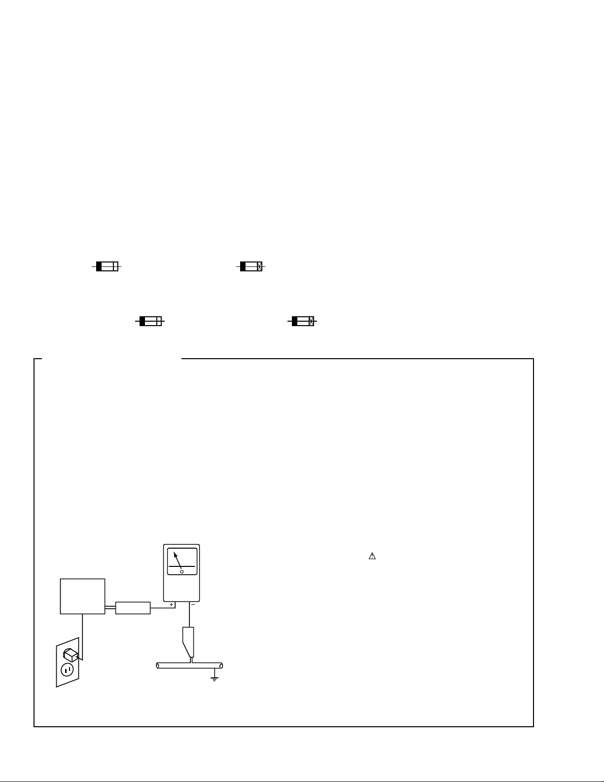
1. SAFETY PRECAUTIONS
The following check should be performed for the
continued protection of the customer and service
technician.
LEAKAGE CURRENT CHECK
Measure leakage current to a known earth ground (water
pipe, conduit, etc.) by connecting a leakage current tester
such as Simpson Model 229-2 or equivalent between the
earth ground and all exposed metal parts of the appliance
(input/output terminals, screwheads, metal overlays, control
shaft, etc.). Plug the AC line cord of the appliance directly
into a 120V AC 60Hz outlet and turn the AC power switch
on. Any current measured must not exceed 0.5mA.
(FOR USA MODEL ONLY)
Leakage
current
tester
Reading should
not be above
0.5mA
Device
under
test
Test all
exposed metal
surfaces
Also test with
plug reversed
(Using AC adapter
plug as required)
Earth
ground
AC Leakage Test
3
DV-37, DV-S77, DV-S737, DV-737, DV-737-K
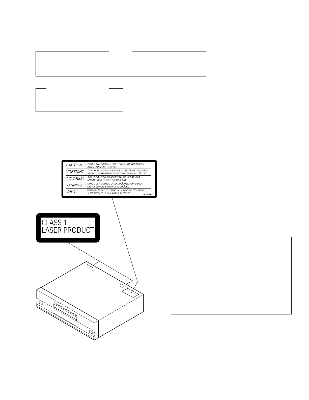
LABEL CHECK (For RL, RL/RD and WY Types)
RL and RL/RD
Types
WY Type
(Printed on the Rear Panel)
WARNING !
THE AEL (ACCESSIBLE EMISSION LEVEL) OF THE LASER POWER OUTPUT IS LESS THAN CLASS 1
BUT THE LASER COMPONENT IS CAPABLE OF EMITTING RADIATION EXCEEDING THE LIMIT FOR
CLASS 1.
A SPECIALLY INSTRUCTED PERSON SHOULD DO SERVICING OPERATION OF THE APPARATUS.
Additional Laser Caution
1. Inside detection switch (S201 on the SMEB assy) and loading-status
detection switch (S301 on the LOSB assy) are detected by the
microprocessor (IC601 in the DVDM assy).
• To permit the laser diode to oscillate, it is required to set the inside
detection switch for the inside position (S201 : ON) and to set the loading-
status detection switch for the clamp position (the center terminal of S301
is shorted to +5V). The 650 nm laser diode for DVD oscillation will continue
if pin 19 of IC101 is shorted to +5V (fault condition) in the DVDM assy.
The 780 nm laser diode for CD oscillates if pin 20 of IC101 is shorted to
+5V in the DVDM assy.
In the test mode ∗ , the laser diode oscillates when microprocessor detects
a PLAY signal, or when the PLAY key is pressed (S106 ON in the FLKY
assy), with the above requirements satisfied.
2. When the cover is open, close viewing through the objective lens with
the naked eye will cause exposure to the laser beam.
∗ : See page 59.
LASER DIODE CHARACTERISTICS
FOR DVD : MAXIMUM OUTPUT POWER : 5 mW
WAVELENGTH : 655 nm
FOR CD : MAXIMUM OUTPUT POWER : 5mW
WAVELENGTH : 785 nm
4
DV-37, DV-S77, DV-S737, DV-737, DV-737-K
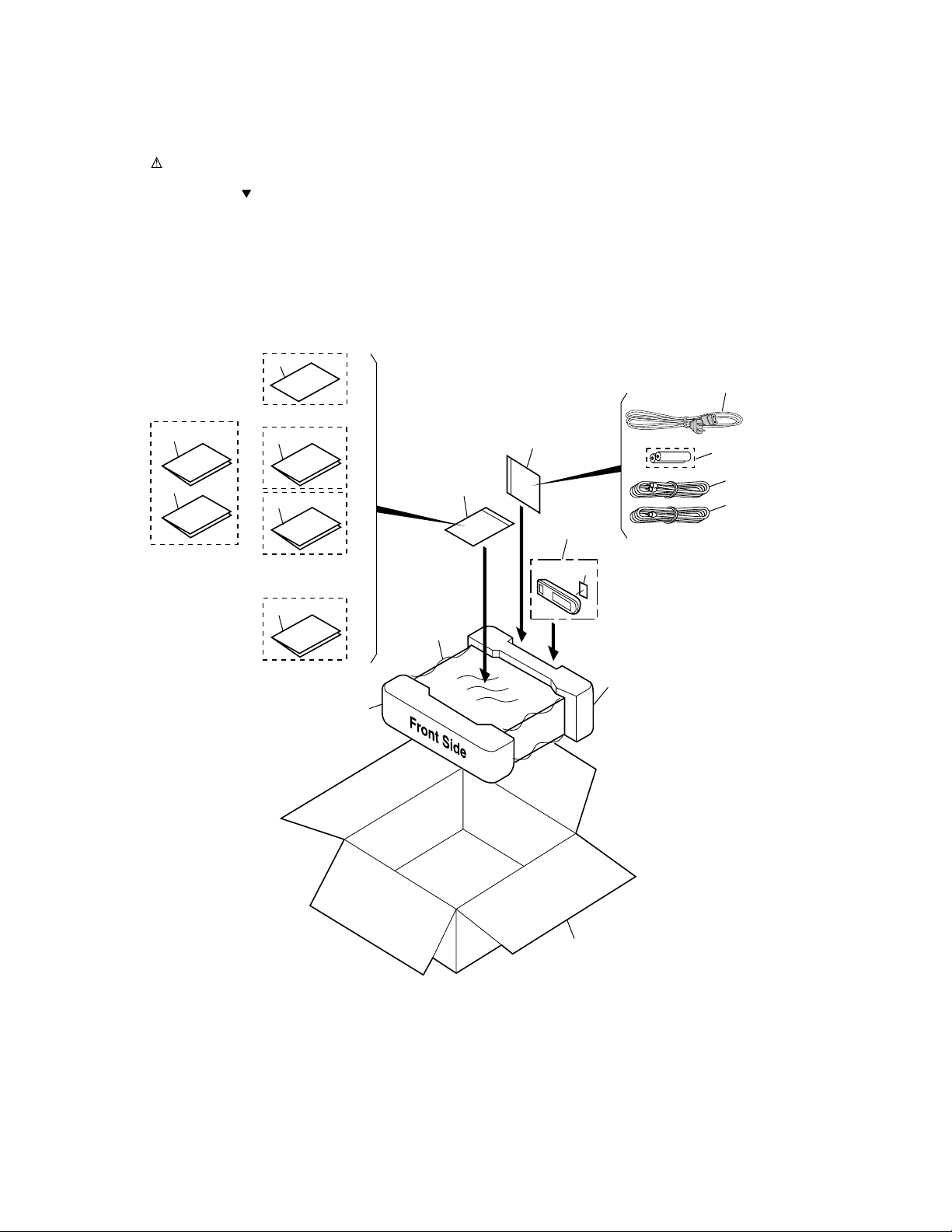
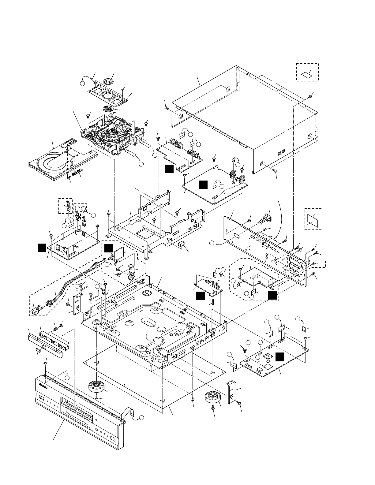
2.1 PACKING
2. EXPLODED VIEWS AND PARTS LIST
NOTES:
•
Parts marked by "NSP" are generally unavailable because they are not in our Master Spare Parts List.
•
The mark found on some component parts indicates the importance of the safety factor of the part.
Therefore, when replacing, be sure to use parts of identical designation.
•
Screws adjacent to mark on the product are used for disassembly.
1
6
5
11
12
9
10
4
3
8
2
8 or 13
7
14
15
16
17
WY Type Only
KU/CA Type Only
KU/CA and WY
Types Only
LB, RL and RL/RD
Types Only
LB and RL
Types Only
18
5
DV-37, DV-S77, DV-S737, DV-737, DV-737-K
1 Power Cord See Contrast table (2)
NSP 2 Warranty Card See Contrast table (2)
3 Audio Cord (L = 1.5m) VDE1033
4 Video Cord (L = 1.5m) VDE1034
5 Remote Control Unit See Contrast table (2)
6 Battery Cover See Contrast table (2)
NSP 7 Dry Cell Battery (R6P, AA) VEM-013
NSP 8 Polyethylene Bag Z21-038
(0.03×230×340)
9 Sheet RHX1006
10 Pad F VHA1240
11 Pad R VHA1241
12 Packing Case See Contrast table (2)
13 Polyethylene Bag B5 See Contrast table (2)
14 Operating Instructions See Contrast table (2)
(English)
15 Operating Instructions See Contrast table (2)
(English)
16 Operating Instructions See Contrast table (2)
(Trad-Chinese)
17 Operating Instructions See Contrast table (2)
(English, French, German, Italian)
18 Operating Instructions See Contrast table (2)
(Dutch, Swedish, Spanish, Danish)
(1) PACKING PARTS LIST
Mark No. Description Part No.
(2) CONTRAST TABLE
DV-37/KU/CA, DV-S77/LB, DV-S737/RL, RL/RD, DV-737/WY and DV-737-K/WY are constructed the same except for the
following :
Mark No. Symbol and Description
Part No.
DV-37
/KU/CA
DV-S77
/LB
DV-S737
/RL
DV-S737
/RL/RD
DV-737
/WY
DV-737-K
/WY
NSP
1
2
5
6
12
13
14
15
16
17
18
Power Cord
Warranty Card
Remote Control Unit
Battery Cover
Packing Case
Polyethylen Bag B5
Operating Instructions (English)
Operating Instructions (English)
Operating Instructions (Trad-Chinese)
Operating Instructions
(English, French, German, Italian)
Operating Instructions
(Dutch, Swedish, Spanish, Danish)
ADG7021
ARY1026
VXX2714
VNK4423
VHG1996
Not used
VRB1262
Not used
Not used
Not used
Not used
ADG7006
Not used
VXX2628
VNK4677
VHG1994
VHL1051
Not used
VRB1255
VRC1121
Not used
Not used
ADG1127
Not used
VXX2628
VNK4677
VHG1995
VHL1051
Not used
VRB1255
VRC1121
Not used
Not used
ADG1127
Not used
VXX2627
VNK4423
VHG1998
VHL1051
Not used
VRB1255
Not used
Not used
Not used
ADG1127
ARY7022
VXX2628
VNK4677
VHG1985
Not used
Not used
Not used
Not used
VRE1086
VRF1055
ADG1127
ARY7022
VXX2627
VNK4423
VHG1997
Not used
Not used
Not used
Not used
VRE1086
VRF1055
6
DV-37, DV-S77, DV-S737, DV-737, DV-737-K
2.2 EXTERIOR SECTION
A
B
B
E
D
C
F
L
M
H
K
F
M
E
L
G
D
K
N
O
A
N
C
G
H
O
F
H
I
G
M
L
E
18
KU/CA and
LB Types
Only
RL, RL/RD and
WY Types
Only
WY Type
Only
KU/CA Type
Only
LB, RL and RL/RD
Types Only
RL, RL/RD and
WY Types
Only
RL, RL/RD and
WY Types
Only
15
31
44
33
34
44
44
23
7
6
44
51
44
44
28
43
27
42
38
37
44
29
47
48
25
26
10 30
8
Refer to
"2.4 LOADING MECHANISM ASSY".
Refer to
"2.3 FRONT PANEL SECTION".
47
4
2
49
21
49
32
36
35
43
43
17
16
44
43
44
17
27
11
12
13
44
44
44
44
44
44
44
44
44
20
24
19
3
39
40
45
45
45
46
44
5
44
44
45
44
44
50
9
22
44
1
14
41
7
DV-37, DV-S77, DV-S737, DV-737, DV-737-K
(1) EXTERIOR SECTION PARTS LIST
Mark No. Description Part No. Mark No. Description Part No.
1 DVDM Assy See Contrast table (2)
2 AJKB Assy See Contrast table (2)
3 DJKB Assy See Contrast table (2)
4 VJKB Assy See Contrast table (2)
5 SCRB Assy See Contrast table (2)
NSP 6 MSWB Assy See Contrast table (2)
7 POWER SUPPLY Unit VWR1333
NSP 8 Loading Mechanism Assy VWT1180
9 AC Inlet Assy See Contrast table (2)
10 Earth Lead Wire DE012VF0
11 Flexible Cable (28P) VDA1845
12 Flexible Cable (18P) VDA1847
13 Flexible Cable (28P) VDA1848
14 Flexible Cable (12P) VDA1849
15 Housing Assy See Contrast table (2)
NSP 16 Bottom Plate PNA2376
17 Insulator PNW2766
18 Tray Stopper Spring VBH1277
19 Mini Card Spacer VEC2173
20 Cushion VEC2174
21 Bonnet S See Contrast table (2)
22 Rear Panel See Contrast table (2)
NSP 23 Sub Chassis See Contrast table (2)
NSP 24 Chassis VNA2246
25 Clamper Plate VNE2068
26 Bridge VNE2069
NSP 27 Panel Stay VNE2156
NSP 28 PCB Stay VNE2214
29 Tray See Contrast table (2)
30 Clamper VNL1738
31 Tray Stopper VNL1739
32 Power Joint See Contrast table (2)
33 Power Button See Contrast table (2)
34 Switch Holder See Contrast table (2)
35 DVD Badge See Contrast table (2)
36 Door Panel See Contrast table (2)
37 Dor Holder See Contrast table (2)
38 Door Spring VBH1331
39 Connector Assy See Contrast table (2)
40 Flexible Cable (20P) See Contrast table (2)
41 Caution Label See Contrast table (2)
42 Screw VBA1057
43 Screw ABZ30P080FMC
44 Screw IBZ30P060FCC
45 Screw BBZ30P080FCC
46 Screw BBZ30P100FZK
47 Screw BBZ30P100FMC
48 Screw BPZ26P080FZK
49 Screw See Contrast table (2)
50 Label See Contrast table (2)
51 Screw See Contrast table (2)
(2) CONTRAST TABLE
DV-37/KU/CA, DV-S77/LB, DV-S737/RL, RL/RD, DV-737/WY and DV-737-K/WY are constructed the same except for the
following :
Mark No. Symbol and Description
Part No.
DV-37
/KU/CA
DV-S77
/LB
DV-S737
/RL
DV-S737
/RL/RD
DV-737
/WY
DV-737-K
/WY
NSP
NSP
1
2
3
4
5
6
9
15
21
22
23
29
32
33
34
35
36
37
39
40
41
49
50
51
DVDM Assy
AJKB Assy
DJKB Assy
VJKB Assy
SCRB Assy
MSWB Assy
AC Inlet Assy
Housing Assy
Bonnet S
Rear Panel
Sub Chassis
Tray
Power Joint
Power Button
Switch Holder
DVD Badge
Door Panel
Door Holder
Connector Assy
Flexible Cable (20P)
Caution Label
Screw
Label
Screw
VWS1416
VWV1761
VWV1788
VWV1791
Not used
Not used
VKP2254
VKP2259
VXX2672
VNA2228
VNA2234
VNL1731
Not used
Not used
Not used
CAH1747
VNK4664
VNK4509
Not used
Not used
Not used
BCZ40P060FZK
VRW1863
Not used
VWS1416
VWV1761
VWV1788
VWV1790
Not used
Not used
VKP2254
VKP2189
VXX2617
VNA2237
VNA2234
VNK4333
Not used
Not used
Not used
VAM1111
VNK4663
VNK4325
Not used
Not used
Not used
BCZ40P060FNI
Not used
Not used
VWS1419
VWV1761
VWV1789
VWV1790
Not used
VWG2247
VKP2255
Not used
VXX2617
VNA2239
VNA2234
VNK4333
VNK4327
VNK4159
VNE2232
VAM1111
VNK4663
VNK4325
Not used
Not used
VRW1699
BCZ40P060FNI
Not used
PMB30P060FZK
VWS1419
VWV1761
VWV1789
VWV1790
Not used
VWG2247
VKP2255
Not used
VXX2672
VNA2257
VNA2234
VNL1731
VNK4327
VNK4184
VNE2232
CAH1747
VNK4665
VNK4509
Not used
Not used
VRW1699
BCZ40P060FZK
Not used
PMB30P060FZK
VWS1419
VWV1762
VWV1789
VWV1792
VWV1793
VWG2247
VKP2255
Not used
VXX2617
VNA2229
VNA2225
VNK4333
VNK4327
VNK4159
VNE2232
VAM1111
VNK4663
VNK4325
PG03KK-F12
VDA1850
VRW1699
BCZ40P060FNI
Not used
PMB30P060FZK
VWS1419
VWV1762
VWV1789
VWV1792
VWV1793
VWG2247
VKP2255
Not used
VXX2672
VNA2227
VNA2225
VNL1731
VNK4327
VNK4184
VNE2232
CAH1747
VNK4665
VNK4509
PG03KK-F12
VDA1850
VRW1699
BCZ40P060FZK
Not used
PMB30P060FZK
8
DV-37, DV-S77, DV-S737, DV-737, DV-737-K
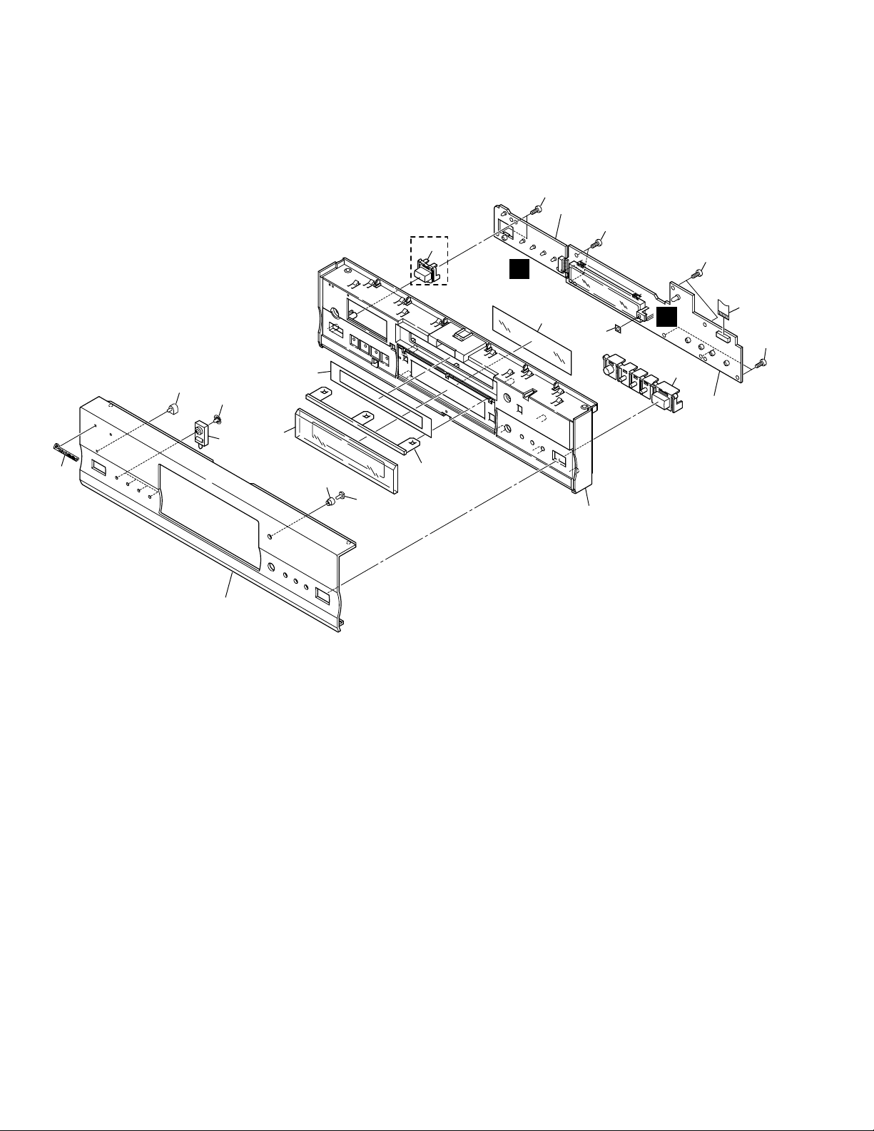
2.3 FRONT PANEL SECTION
K
J
KU/CA and LB
Types Only
11
18
8
17
19
16 (1/2)
13
10
12
16 (2/2)
14 or 15
9
6
5
4
7
1
3
2
18
18
18
9
DV-37, DV-S77, DV-S737, DV-737, DV-737-K
(1) FRONT PANEL SECTION PARTS LIST
Mark No. Description Part No.
1 FLKY Assy See Contrast table (2)
NSP 2 PWSB Assy See Contrast table (2)
3 Flexible Cable (16P) VDA1846
4 Pioneer Badge See Contrast table (2)
5 LED Lens PNW2019
6 DISP Lens PNW2113
7 DVD Ring VAK1008
8 FL Filter See Contrast table (2)
9 FL Lens See Contrast table (2)
10 Door Sheet See Contrast table (2)
11 PW Button See Contrast table (2)
12 LED Lens VNK4326
13 Sub Panel See Contrast table (2)
14 Front Panel See Contrast table (2)
15 Front Almi. See Contrast table (2)
16 Panel Base See Contrast table (2)
17 Main Key See Contrast table (2)
18 Screw BBZ30P080FCC
NSP 19 Remote Control Sheet AEE7021
(2) CONTRAST TABLE
DV-37/KU/CA, DV-S77/LB, DV-S737/RL, RL/RD, DV-737/WY and DV-737-K/WY are constructed the same except for the
following :
Mark No. Symbol and Description
Part No.
DV-37
/KU/CA
DV-S77
/LB
DV-S737
/RL
DV-S737
/RL/RD
DV-737
/WY
DV-737-K
/WY
NSP
1
2
4
8
9
10
11
13
14
15
16
17
FLKY Assy
PWSB Assy
Pioneer Badge
FL Filter
FL Lens
Door Sheet
PW Button
Sub Panel
Front Panel
Front Almi.
Panel Base
Main Key
VWG2214
VWG2219
PAN1376
VEC1966
VEC2151
VEC2153
VNK4101
VNK4791
VNK4659
Not used
VNK4662
VNK4667
VWG2215
VWG2221
PAN1377
VEC2189
VEC2150
VEC2152
VNK4059
VNK4657
Not used
VAH1352
VNK4660
VNK4666
VWG2216
VWG2220
PAN1377
VEC2189
VEC2150
VEC2152
Not used
VNK4657
Not used
VAH1353
VNK4660
VNK4666
VWG2216
VWG2220
PAN1376
VEC1965
VEC2151
VEC2153
Not used
VNK4791
Not used
VAH1349
VNK4662
VNK4667
VWG2217
VWG2220
PAN1377
VEC2189
VEC2150
VEC2152
Not used
VNK4657
Not used
VAH1348
VNK4660
VNK4666
VWG2217
VWG2220
PAN1376
VEC1965
VEC2151
VEC2153
Not used
VNK4791
Not used
VAH1345
VNK4662
VNK4667
10
DV-37, DV-S77, DV-S737, DV-737, DV-737-K
11
13
12
3
15
16
8
7
17
2
10
18
21
9
22
14
4
5
6
1
• Top View • Bottom View
19
20
Refer to
"TRAVERSE MECHANISM ASSY-S".
B
A
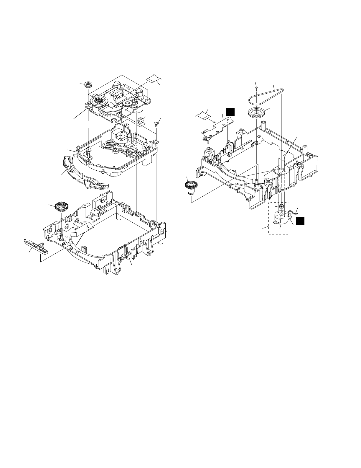
2.4 LOADING MECHANISM ASSY
1 Traverse Mechanism Assy-S VXX2653
NSP 2 LOSB Assy VWG1885
NSP 3 LOMB Assy VWG1886
4 Drive Gear VNL1735
5 Lock Plate VNL1820
6 Loading Base VNL1730
7 Belt VEB1260
8 Gear Pulley VNL1733
9 Screw DBA1006
10 Loading Gear VNL1734
11 Loading Motor Assy VXX2505
12 DC Motor / 0.3W (LOADING) PXM1027
13 Motor Pulley PNW1634
14 Drive Cam VNL1736
15 Connector Assy VKP2198
(LOMB CN401 ↔ LOSB CN303)
16 Screw VBA1055
17 Screw Z39-019
18 Flexible Cable (08P) VDA1698
(LOSB CN302 ↔ SMEB CN202)
19 Float Base VNL1867
20 Floating Rubber VEB1286
21 Flexible Cable (24P) VDA1701
(Pickup Assy ↔ DVDM CN120)
22 Cushion VEB1312
•
LOADING MECHANISM ASSY PARTS LIST
Mark No. Description Part No. Mark No. Description Part No.
11
DV-37, DV-S77, DV-S737, DV-737, DV-737-K
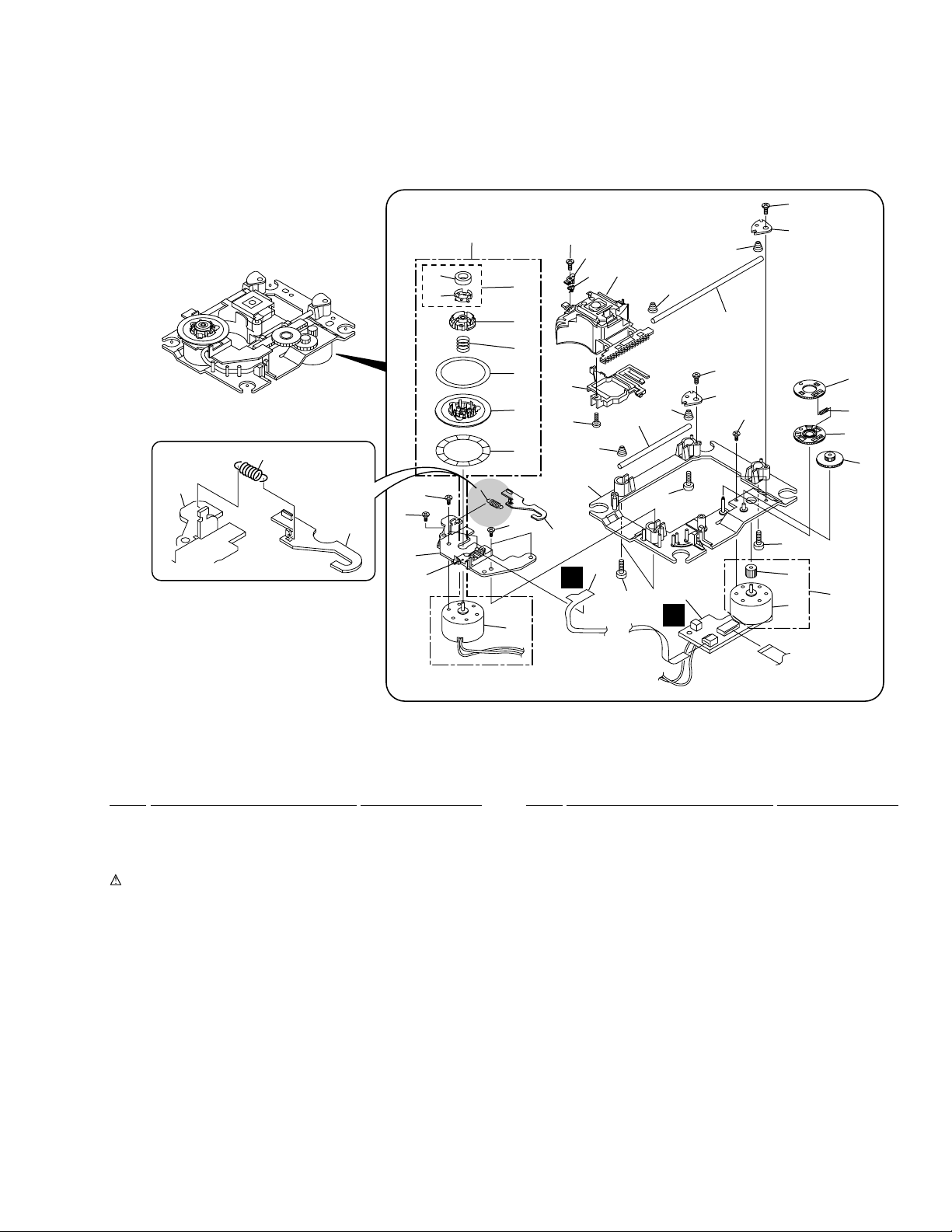
2.5 TRAVERSE MECHANISM ASSY-S
21
9
17
• Top View
30
16
34
19
8
15
10
10
22
33
23
5
14
10
37
18
32
13
10
37
18
26
25
27
29
7
7
7
3
1
11
28
33
6
35
20
12
21
4
9
31
37
17
24
37
36
2
C
D
NSP 1 SMEB Assy VWG2048
NSP 2 FGSB Assy VWG2009
NSP 3 Motor (CARRIAGE) VXM1079
NSP 4 Motor (SPINDLE) VXM1084
NSP 5 Pickup Assy VWY1055
6 Table Sheet DEC2040
7 Screw VBA1058
8 Centering Spring VBH1278
9 Hook Spring VBH1317
10 Skew Spring VBH1303
11 Gear Spring VBH1308
NSP 12 Reflected Sheet VEC1959
13 Guide Bar VLL1504
14 Sub-guide Bar VLL1505
15 Hold Spring VNC1017
NSP 16 Magnet Holder VNE2070
NSP 17 Motor Base VNE2154
NSP 18 Cover VNE2155
19 Centering Ring VNL1746
NSP 20 Disc Table VNL1747
21 Hook VNL1770
22 FFC Holder VNL1802
23 Mechanism Base VNL1806
24 FG Holder VNL1807
25 Gear A VNL1808
26 Gear B VNL1809
27 Gear C VNL1810
28 Slider VNL1811
29 Gear D VNL1814
NSP 30 Magnet VYM1024
31 Screw JFZ17P025FZK
32 Screw JGZ17P028FMC
33 Screw VBA1051
34 Magnet Holder Assy VXX2507
35 Spindle Motor Assy VXX2649
36 Carriage Motor Assy VXX2650
37 Screw PBA1069
•
TRAVERSE MECHANISM ASSY-S PARTS LIST
Mark No. Description Part No. Mark No. Description Part No.
DV-37, DV-S77, DV-S737, DV-737, DV-737-K
12
A
B
C
D
1
23
4
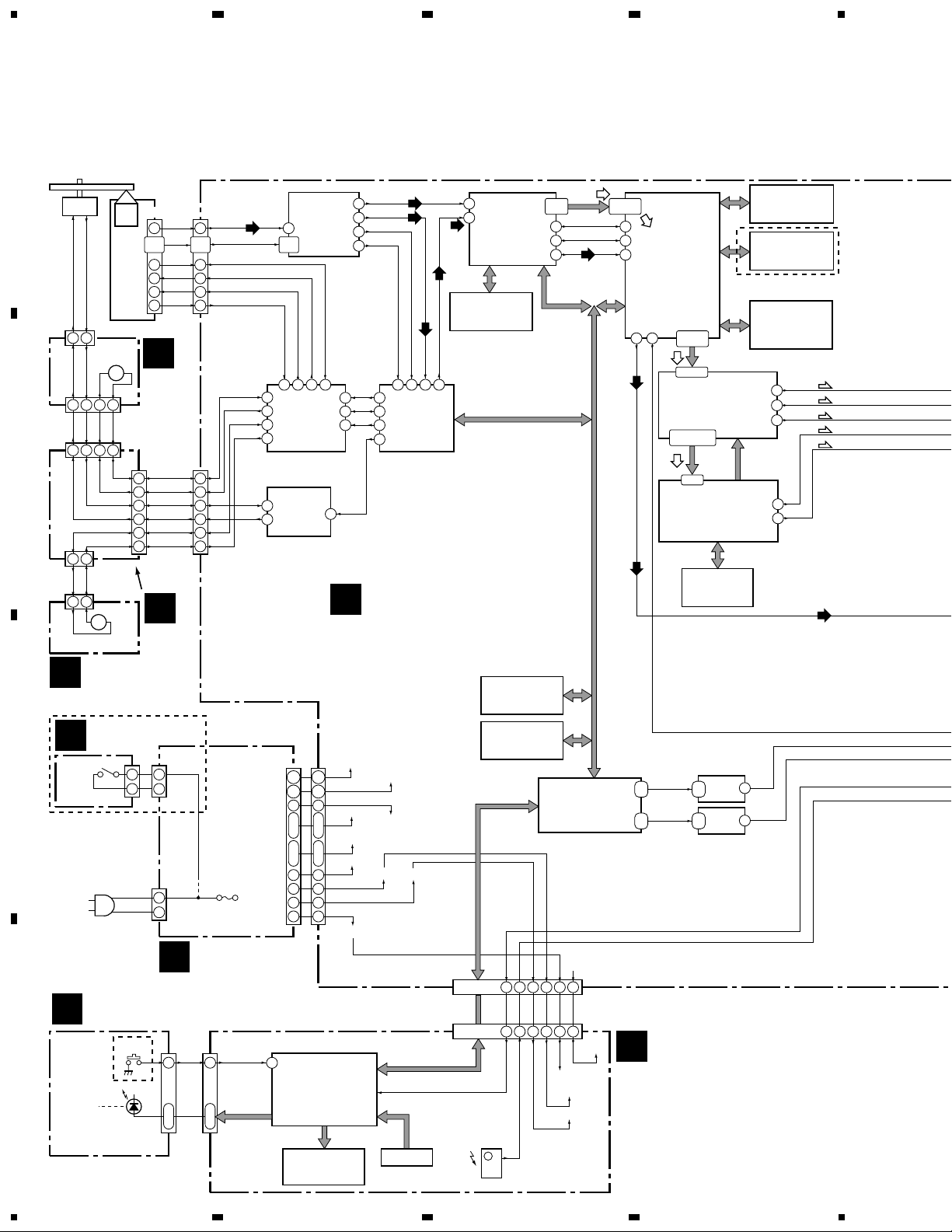
1234
Spindle
Motor
Carriage
Motor
Assy
Loading
Motor Assy
F_DRV
F_DRV
15
4
1
3
2
22,23
18,19
10
21
24
22
23
3,2
7,6
OEIC
Pickup
Assy
F_RTN
F_RTN
SPDL+
SPDL-
SPDL+
SPDL-
SLDRF
SLDRR
SLDRR
SLDRR FDO
TDO
SLDO
SEL IR
IR
12V
12V
SLDRF
SLDRF
SPDL-
SPDL+
LOAD+
LOAD-
LOAD+
LOAD-
LOAD+
LOAD-
B1-B4
B1-B4
RF
RF
RFO
CDLRCK
VIDEO
DATA
CDBCLK
CDDATA
DOUT0
Y
Cb
Cr
AOD
AIN
ROMXA
DSPRF
T_DRV
T_DRV
T_RTN
T_RTN
CN203
CN302
13
12
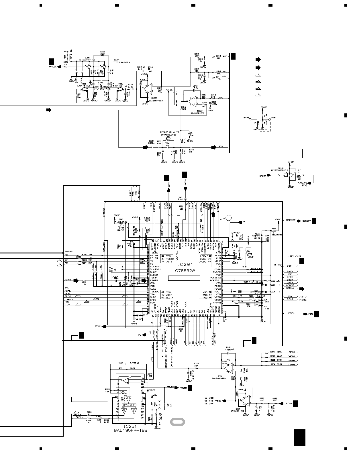
IC251
BA6195FP
Spindle
Driver
IC351
M56788FP
FTS Driver
IC101
LA9710M
RF IC
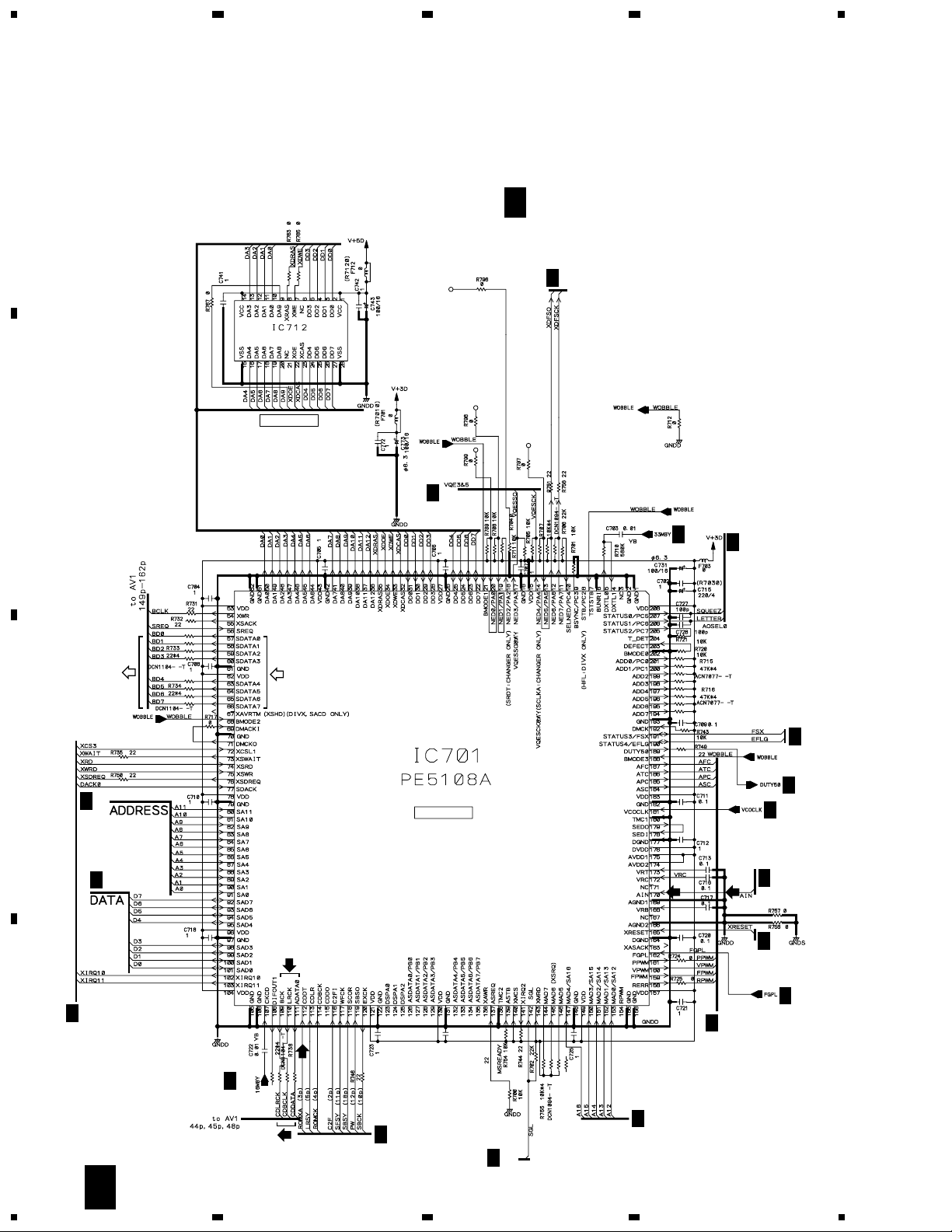
IC701
PE5108A
DVD Decoder
BY Chip
IC1001
PM0024AF
Video Encoder
VQE-3
IC1003
PM0030A
VQE-5
IC712
MNR4800DJ7-TBB
4M DRAM
IC1002
HY58163210TQ-10F
SG RAM
IC805
MB81F161622C-80FN
16M SDRAM
IC806
MB81F161622C-80FN
16M SDRAM
IC801
M65774FP
AV-1
IC201
LC78652W
Servo
DSP IC
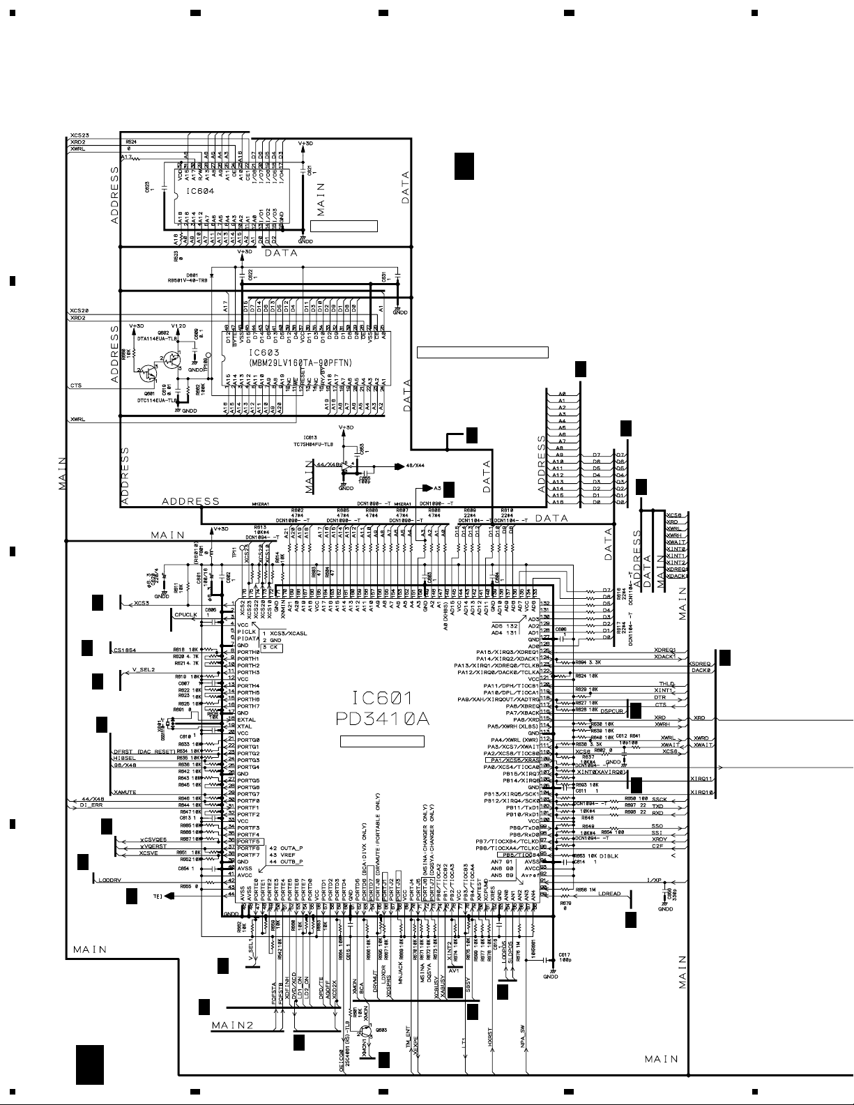
IC601
PD3410A
System Control
SH1 Base ASIC
IC603
VYW1738
16M FLASH MEM.
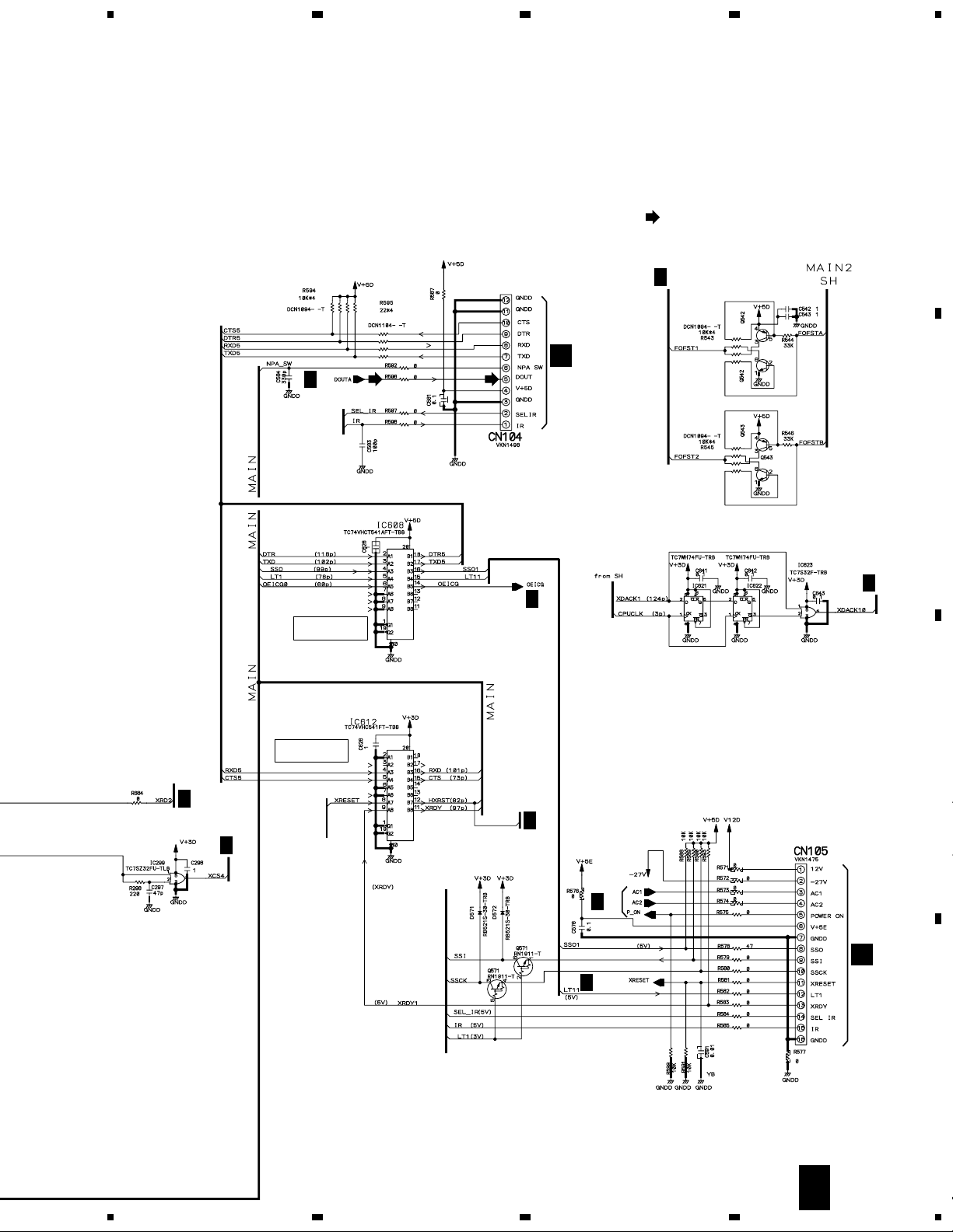
IC608
TC74VHCT541AFT
3→5 Converter
C
SMEB
ASSY
B
LOSB
ASSY
A
LOMB
ASSY
E
DVDM ASSY
+8V (M)
V+8
+12V (A)
-12V (A)
SW+5V
SW+3.3V
EV+5V
AC_A
AC_B
-27V
RL, RL/RD, WY
ONLY
RL, RL/RD, WY
ONLY
KU/CA, LB
ONLY
L
MSWB
ASSY
M
POWER
SUPPLY
UNIT
K
PWSB
ASSY
J
FLKY ASSY
9
24
26
27
28
LIVE
POWER
S1000
POWER
S201
NEUTRAL
AC IN
1,2
5,6
12
|
13
14
|
18
IC101
PE5185A
FL Control IC
V101
VAW1060
FL TUBE
IR101
REMOTE
SENSOR
(24P)
(8P)
CN401
CN303
CN2
CN301
(12P)
CN201
(28P)
CN101
(28P)
CN201
(8P)
CN102
(8P)
CN101
(16P)
CN105
(16P)
CN512
(12P)
CN202
(8P)
CN120
(24P)
1 2
M
7 8 3 5
2 1 6 4
3
5
9
7
6
4
10
8
4
6
7
9
2 1
1 2
M
2
1
2
1
CN1
2
1
V+5
V+3
12V
-27V
AC
AC
AC
AC
-27V
V5EV
AC1
AC2
-27V
V+12
V-12
9
24
26
27
28
1,2
102
118
3
2
5,6
12
|
13
14
|
18
3 3
4
|
6
4
|
6
IC803
M5M4V18165DTP-6S
1M×16
EDO DRAM
IC604
TC55V1001AF8
WORK SRAM
ADDRESS, DATA BUS
Y0-Y9,
CR0-CR9,
CB0-CB9
CONTROL
26
KEY SW
161513 14
34
13
5
54
170
112
109
110
111
46
FE
TE
DSPRF
ROMXA
FE
TE
42
35
12 10 9 32 33 39 3
44
45
48
74
103
101
99
68
35
14
3
20
37
47
48
45
46
15
6-9,
11,12
SPDO
TXD,DTR
TXD5
RXD5
SPDO
25
57-60
63-66
80-84
78,86,87
103-100,
98-95
84,82,81,79,
78,76-74
118-111
17-24
17
IC612
TC74VHCT541AFT
5→3 Converter
101
117
RXD,DTR
16
4
5
Y
50
C
53
124 31514
23
(Y)
(Cb)
(Cr)
(Y)
(C)
(RF)
(RF)
(RF)
(RF)
(RF)
(RF)
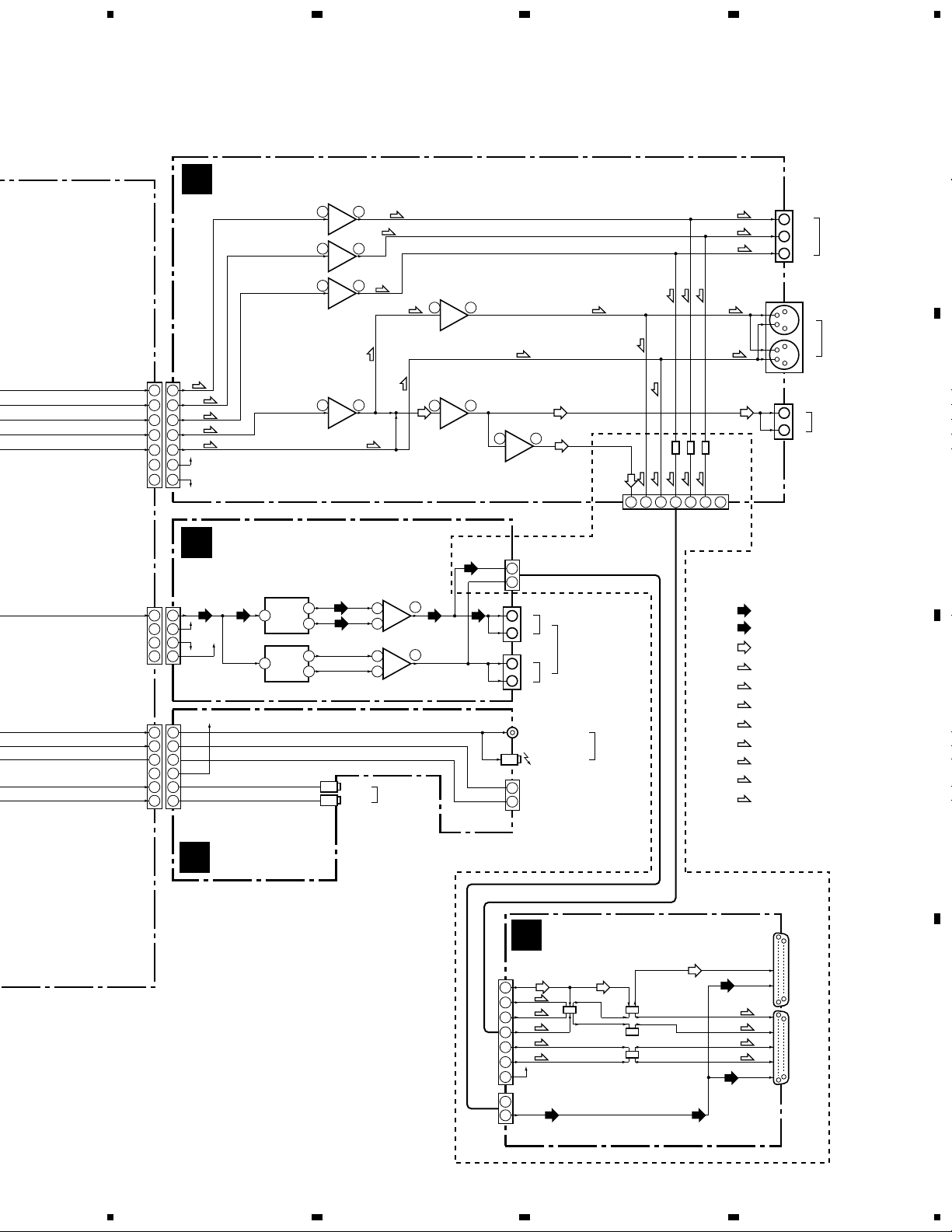
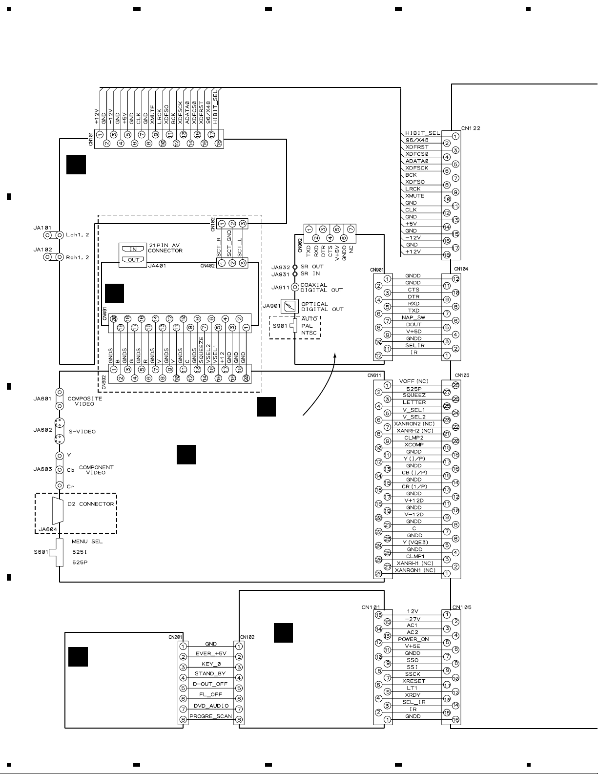
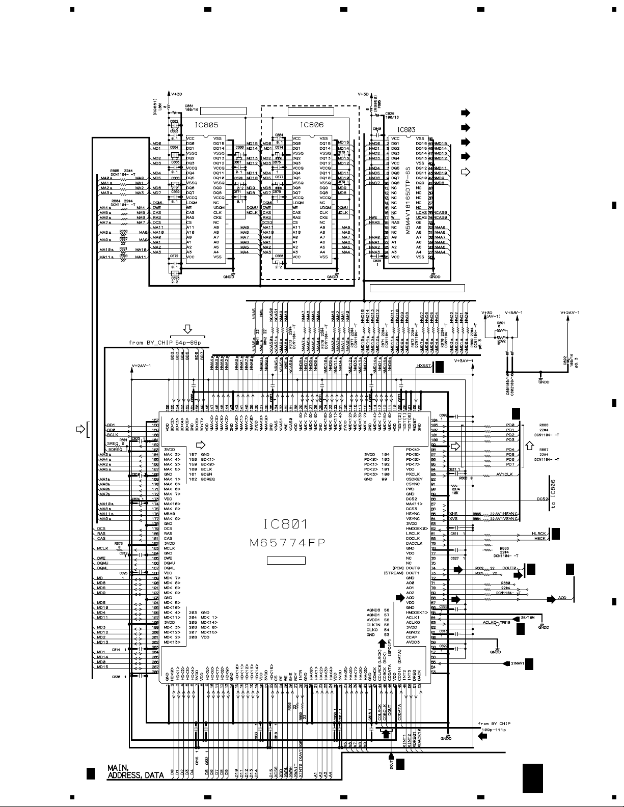
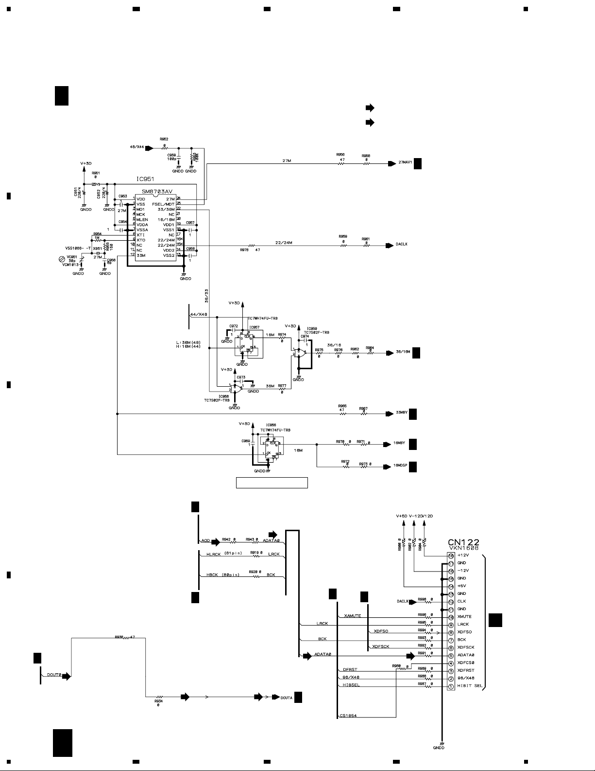
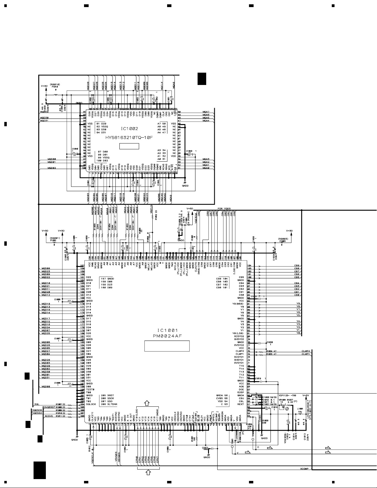
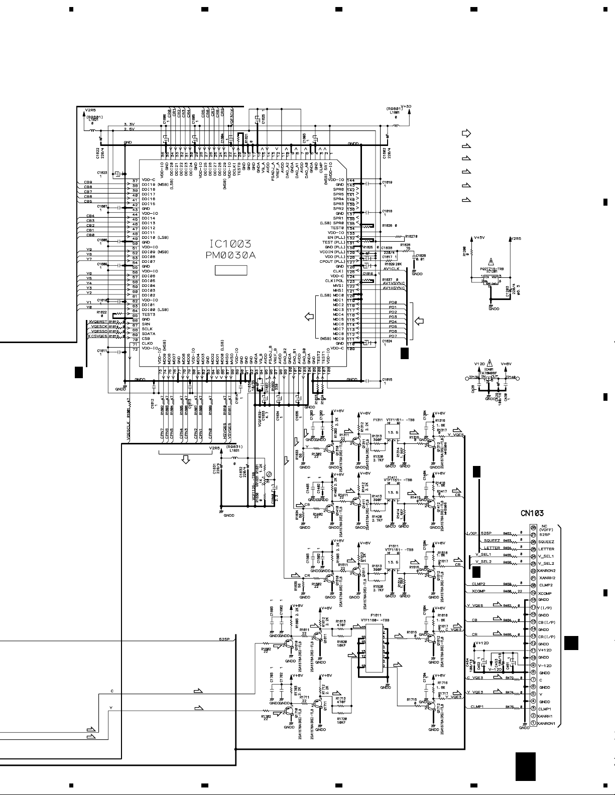
3. BLOCK DIAGRAM AND SCHEMATIC DIAGRAM
3.1 BLOCK DIAGRAM
DV-37, DV-S77, DV-S737, DV-737, DV-737-K
13
A
B
C
D
5
678
5
6
7
8
Cb
Cr
ADATA0
+5V
V+5D
V+12A
V+12V
V
Y
C
R
G
B
V+12V
V-12V
V+5V
V-12A
HDATA
HDATA
-12V
+12V
WY
ONLY
CN122
(16P)
CN101
(16P)
16
18
14
5
3
1
CN102
(3P)
CN692
(20P)
3
1
3
1
5
14
2
1
L ch
R ch
Y
Y
C
V+12D
V-12D
CN103
(28P)
CN611
(28P)
17
15
13
5
7
11
9
12
14
16
24
22
18
20
8
10
12
6
4
2
17
CN491
(20P)
CN402
(3P)
13
11
9
15
17
19
4
DOUT
SEL IR
V+5D
RXD
TXD
RXD
TXD
V
Y
C
R
G
B
G
B
L OUT
R/C
V/Y
L OUT
V OUT
SCT R
SCT L
SCT R
SCT L
IR
CN104
(12P)
CN901
(12P)
CN902
(7P)
7
4
2
1
8
5
6
4
2
1
7
5
F
AJKB ASSY
H
VJKB ASSY
G
DJKB ASSY
I
SCRB ASSY
VIDEO OUT
JA601
1
2
JA602
1
2
IC103
AD1854JRS
27
17
16
IC104
AD1854JRS
27
12
13
6
7
2/2
IC101
NJM5532MD
IC604
TK15420M
IC102
NJM5532MD
AUDIO OUT
JA101
JA102
1
2
L
1
2
R
JA911
JA401(1/2)
JA401(2/2)
JA901
JA932
JA931
DIGITAL
OUT
For
Download
OPTICAL
AV2
AV1
COAXIAL
IN
OUT
CONTROL
5
3 1
1/2
6
7
2/2
5
COMPONENT
VIDEO OUT
S-VIDEO OUT
JA603
Y
P
B
P
R
V+12V
IC603
TK15420M
5 7
2/2
IC603
TK15420M
3 1
1/2
IC601
TK15420M
IC601
TK15420M
IC602
TK15420M
IC602
TK15420M
RY601
RY602
3 1
1/2
5 7
2/2
3 1
1/2
5 7
2/2
RY401
RY406
RY405
RY404
: AUDIO SIGNAL ROUTE
: AUDIO SIGNAL ROUTE
: VIDEO SIGNAL ROUTE
: Y SIGNAL ROUTE
(Y)
(Y)
(V/Y)
(R/C)
(C)
(R)
(G) (G)
(B) (B)
(Y)
(Y) (Y)
(R)
(Cb)
(Cb) (Cb)
(Cr)
(Cr)
(C)
(Y)
(C)
(Y)
(G)
(B)
(Cr)
(Y)
(Cb)
(Cr)
(Y)
(Y)
(Y)
(C)
(Y) (Y)
(C)
(C)
(C) (C)
(RF)
: C SIGNAL ROUTE
(C)
: R SIGNAL ROUTE
(R)
: G SIGNAL ROUTE
(G)
: B SIGNAL ROUTE
(B)
: CR SIGNAL ROUTE
(Cr)
: Cb SIGNAL ROUTE
(Cb)
: Y SIGNAL ROUTE
(Y)
DV-37, DV-S77, DV-S737, DV-737, DV-737-K
14
A
B
C
D
1
23
4
1234
AJKB ASSY
(KU/CA, LB, RL, RL/RD : VWV1761)
(WY : VWV1762)
F
VJKB ASSY
(KU/CA : VWV1791)
(LB, RL, RL/RD : VWV1790)
(WY : VWV1792)
H
DJKB ASSY
(KU/CA, LB : VWV1788)
(RL, RL/RD, WY : VWV1789)
G
PWSB ASSY
(KU/CA : VWG2219)
(LB : VWG2221)
(RL, RL/RD, WY : VWG2220)
K
FLKY ASSY
(KU/CA : VWG2214)
(LB : VWG2215)
(RL, RL/RD : VWG2216)
(WY : VWG2217)
J
SCRB ASSY (VWV1793)
WY
ONLY
WY ONLY
RL, RL/RD,
WY ONLY
LB, RL, RL/RD
ONLY
I
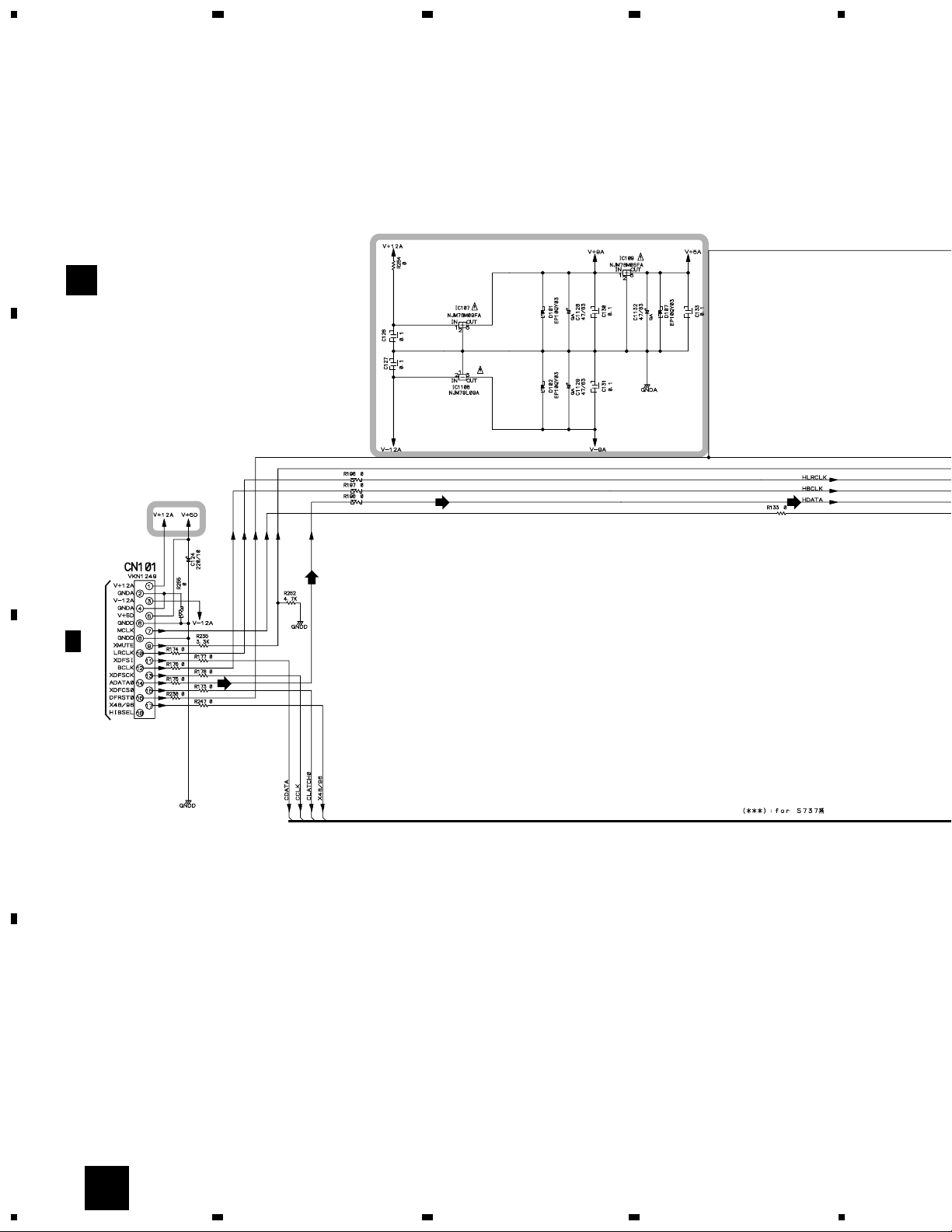
3.2 LOMB, LOSB, SMEB, FGSB, MSWB ASSYS and OVERALL WIRING
DIAGRAM
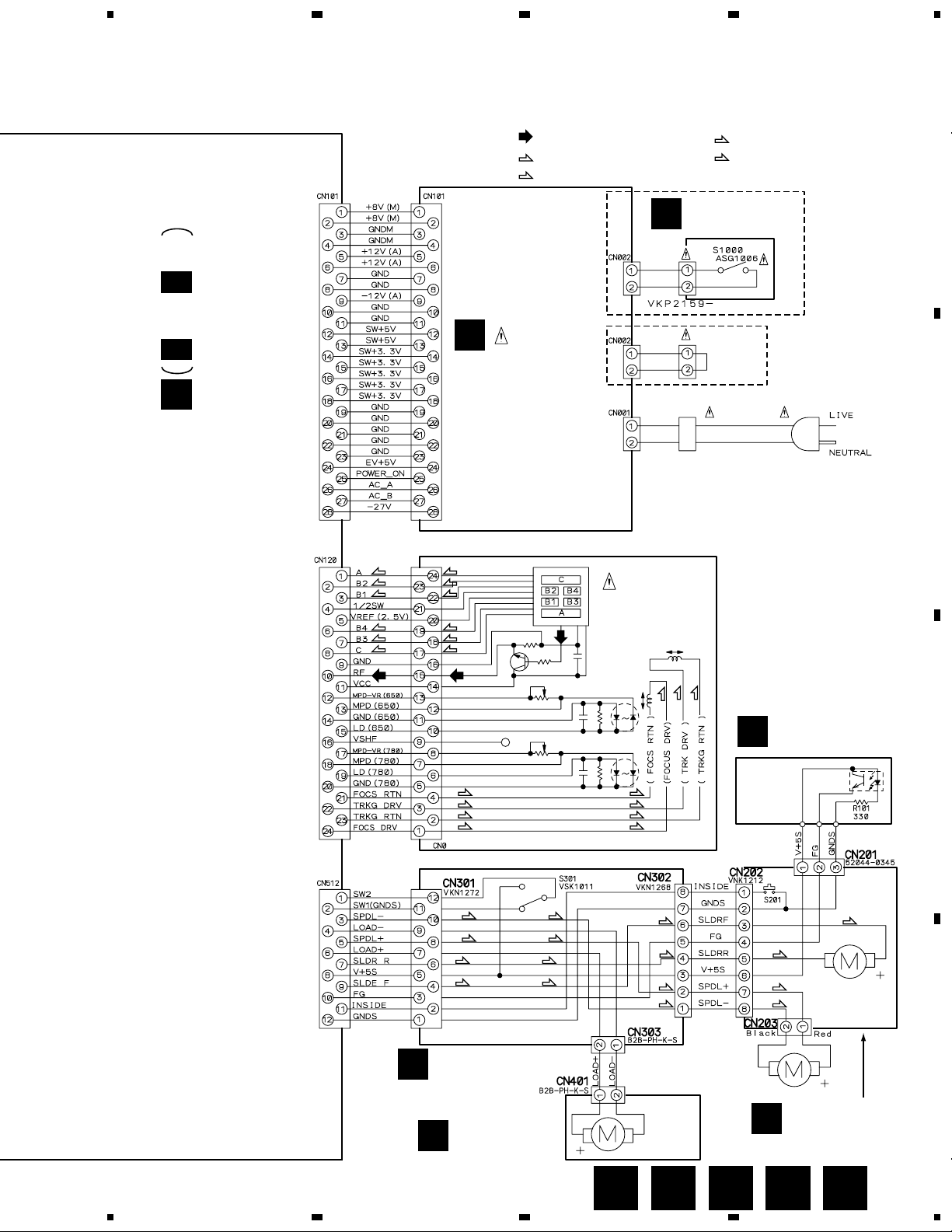
DV-37, DV-S77, DV-S737, DV-737, DV-737-K
15
A
B
C
D
5
678
5
6
7
8
E 1/5- E 5/5
DVDM ASSY
(KU/CA, LB : VWS1416)
(RL, RL/RD, WY : VWS1419)
E
FGSB ASSY
(VWG2009)
D
LOSB ASSY
(VWG1885)
B
LOMB ASSY
(VWG1886)
A
SMEB ASSY
(VWG2048)
C
POWER SUPPLY
UNIT
(VWR1333)
PICKUP ASSY
(VWY1055)
M
MSWB ASSY
(VWG2247)
L
RL, RL/RD,
WY ONLY
KU/CA, LB
ONLY
HOUSING
ASSY
VKP2189
AC INLET ASSY
KU/CA, LB : VKP2254
RL, RL/RD, WY : VKP2255
POWER CORD
KU/CA : ADG7021
LB : ADG7006
RL, RL/RD, WY : ADG1127
LOADING
MOTOR
ASSY
VXX2505
SPINDLE
MOTOR
ASSY
VXX2649
CARRIAGE
MOTOR
ASSY
VXX2650
DSG1016
PC101
GP2S60
: RF SIGNAL ROUTE
: FOCUS SERVO LOOP LINE
: TRACKING SERVO LOOP LINE
(F)
(RF)
(RF) (RF)
(RF)
(T)
: SLIDER SERVO LOOP LINE
(S)
: SPINDLE SERVO LOOP LINE
(SP)
(F)
(F)
(F)
(F)
(T)
(T)
(F)
(F)
(F)
(F)
(T)
(T)
(F)
(F)
(T)
(T)
(F)
(F)
(T)
(F)
(T)
(T)
(T)
(S)
(S)
(SP)
(SP)
(S)
(S)
(S)
(S)
(S)
(S)
(SP)
(SP)
(SP)
(SP)
(SP)
(SP)
Note : When ordering service parts, be sure to refer to "EXPLODED VIEWS and PARTS LIST" or "PCB PARTS LIST".
DCBA L
DV-37, DV-S77, DV-S737, DV-737, DV-737-K
16
A
B
C
D
1
23
4
1234
E 1/5
DVDM ASSY
(KU/CA, LB : VWS1416)
(RL, RL/RD, WY : VWS1419)
HN1A01F
HN1C01FU
HN1C01FU
HN1B04FU
HN1C01FU
HN1C01FU
HN1A01F
HN1C01F
HN1B04FU
HN1A01F
2/5
E
2/5
E
2/5
E
2/5
E
2/5
E
2/5
E
2/5
E
2/5
E
CN301
B
PICKUP ASSY
CN101
M
RF IC
FTS
DRIVER
(RF)
(RF)
(RF)
(RF)
(RF)
(RF)
(RF)
(RF)
(RF)
(RF)
(RF)
(T)
(T)
(F)
(F)
(F)
(F)
(F)
(F)
(F)
(T) (T)
(T)
(T)
(T)
(T)
(T)(T)
(F)
(F) (F)
(F)
(T)
(S)
(S)
(T)
(F)
(SP)
(SP)
(S)
(S)
(CD)
(CD)
(CD)
4
1
2
3
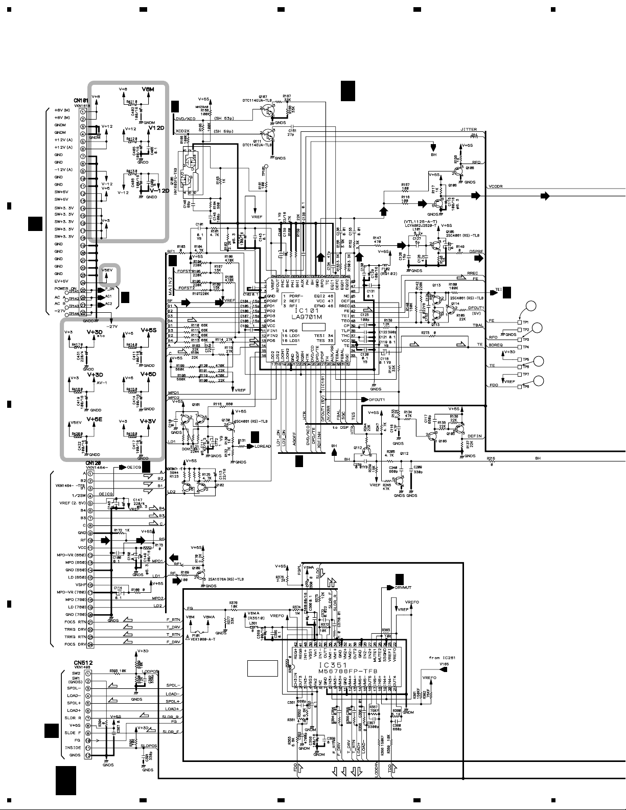
1/5
E
3.3 DVDM ASSY (1/5)
DV-37, DV-S77, DV-S737, DV-737, DV-737-K
17
A
B
C
D
5
678
5
6
7
8
2/2
2/2
1/2
1/2
LANDMARK
FOR CHEKER
KU/CA, LB
ONLY
3/5
E
3/5
E
3/5
E
4/5
E
2/5
E
3/5
E
3/5
E
2/5
E
2/5
E
2/5
E
3/5
E
SPINDLE DRIVER
SERVO DSP IC
3 → 5
CONVERTER
: RF SIGNAL ROUTE
: FOCUS SERVO LOOP LINE
: TRACKING SERVO LOOP LINE
(F)
(RF)
: CD DATA SIGNAL ROUTE
(CD)
(T)
: SLIDER SERVO LOOP LINE
(S)
: SPINDLE SERVO LOOP LINE
(SP)
(RF)
(RF) (RF)
(T)
(T)
(S)
(T)
(E)
(F)
(F)
(SP)
(SP)
(SP)
(T)
(S)
(F)
: The power supply is shown with the marked box.
(CD)
(CD)
(CD)
(CD)
5
1/5
E
DV-37, DV-S77, DV-S737, DV-737, DV-737-K
18
A
B
C
D
1
23
4
1234
20MHz
E 2/5
DVDM ASSY
(KU/CA, LB : VWS1416)
(RL, RL/RD, WY : VWS1419)
1/5
E
1/5
E
1/5
E
1/5
E
1/5
E
1/5
E
1/5
E
1/5
E
1/5
E
1/5
E
1/5
E
3/5
E
3/5
E
3/5
E
5/5
E
5/5
E
5/5
E
4/5
E
4/5
E
3/5
E
3/5
E
3/5
E
3/5
E
TC55V1001AF8
VYW1738
WORK SRAM
PGM 16M FLASH MEMORY
SH1 BASE ASIC
2/5
E
3.4 DVDM ASSY (2/5)
DV-37, DV-S77, DV-S737, DV-737, DV-737-K
19
A
B
C
D
5
678
5
6
7
8
1/5
E
1/5
E
1/5
E
1/5
E
1/5
E
3/5
E
3/5
E
4/5
E
1/5,3/5
E
CN101
J
CN901
G
3 → 5
CONVERTER
5 → 3
CONVERTER
HN1B04FU
HN1B04FU
: AUDIO SIGNAL ROUTE (DIGITAL)
(D)
(D)
(D)
2/5
E
DV-37, DV-S77, DV-S737, DV-737, DV-737-K
20
A
B
C
D
1
23
4
1234
MNR4800DJ7-TBB
4M DRAM
BY CHIP
E 3/5
DVDM ASSY
(KU/CA, LB : VWS1416)
(RL, RL/RD, WY : VWS1419)
4/5
E
4/5
E
5/5
E
5/5
E
1/5
E
1/5
E
1/5
E
1/5
E
1/5
E
2/5
E
2/5
E
2/5
E
4/5
E
1/5
E
1/5
E
2/5
E
2/5
E
5/5
E
(RF)
(RF)
(RF)
(CD)
3/5
E
3.5 DVDM ASSY (3/5)
DV-37, DV-S77, DV-S737, DV-737, DV-737-K
21
A
B
C
D
5
678
5
6
7
8
AV-1
16M SDRAM
16M SDRAM
1M × 16 EDO DRAM (TSOP)
MB81F161622C-80FN
MB81F161622C-80FN
RL, RL/RD, WY
ONLY
2/5
E
1/5,2/5
E
4/5
E
4/5
E
4/5
E
4/5
E
4/5
E
5/5
E
2/5
E
: CD DATA SIGNAL ROUTE
: AUDIO SIGNAL ROUTE
(CD)
: RF SIGNAL ROUTE
(RF)
: VIDEO SIGNAL ROUTE
: AUDIO SIGNAL ROUTE (DIGITAL)
(D)
(D)
(D)
3/5
E
DV-37, DV-S77, DV-S737, DV-737, DV-737-K
22
A
B
C
D
1
23
4
1234
E 4/5
DVDM ASSY
(KU/CA, LB : VWS1416)
(RL, RL/RD, WY : VWS1419)
3/5
E
3/5
E
3/5
E
3/5
E
3/5
E
3/5
E
1/5
E
3/5
E
3/5
E
2/5
E
2/5
E
CN101
F
CLOCK GEN. BLOCK
: AUDIO SIGNAL ROUTE
: AUDIO SIGNAL ROUTE (DIGITAL)
(D)
(D)
(D) (D)
4/5
E
3.6 DVDM ASSY (4/5)

23
DV-37, DV-S77, DV-S737, DV-737, DV-737-K
DV-37, DV-S77, DV-S737, DV-737, DV-737-K
24
A
B
C
D
1
23
4
1234
SGRAM
VQE-3
VIDEO ENCODER IC
E 5/5
DVDM ASSY
(KU/CA, LB : VWS1416)
(RL, RL/RD, WY : VWS1419)
3/5
E
3/5
E
2/5
E
(Y)
(C)
(Y)
(C)
5/5
E
3.7 DVDM ASSY (5/5)
DV-37, DV-S77, DV-S737, DV-737, DV-737-K
25
A
B
C
D
5
678
5
6
7
8
5/5
E
VQE-5
VKN1618
3/5
E
3/5
E
2/5,3/5
E
2/5
E
CN611
H
: VIDEO SIGNAL ROUTE
: Y SIGNAL ROUTE
(Y)
: C SIGNAL ROUTE
(C)
: CR SIGNAL ROUTE
(Cr)
: Cb SIGNAL ROUTE
(Cb)
(Cb)
(Cb)
(Cb)
(Cb)
(Cb)
(Cb)
(Cr)
(Cr)
(Cr)
(Cr)
(Cr)
(Cr)
(Y)
(Y)
(Y)
(Y)
(Y)
: Y SIGNAL ROUTE
(Y)
(Y)
(Y)
(Y)
(Y)
(Y)
(C)
(Y)
(Y)
(Y)
(C)
(C)
(C)
(C)
(C)
(C)
(C)
DV-37, DV-S77, DV-S737, DV-737, DV-737-K
26
A
B
C
D
1
23
4
1234
CN122
E 4/5
AJKB ASSY
(KU/CA, LB, RL, RL/RD : VWV1761)
(WY : VWV1762)
F
F
3.8 AJKB ASSY
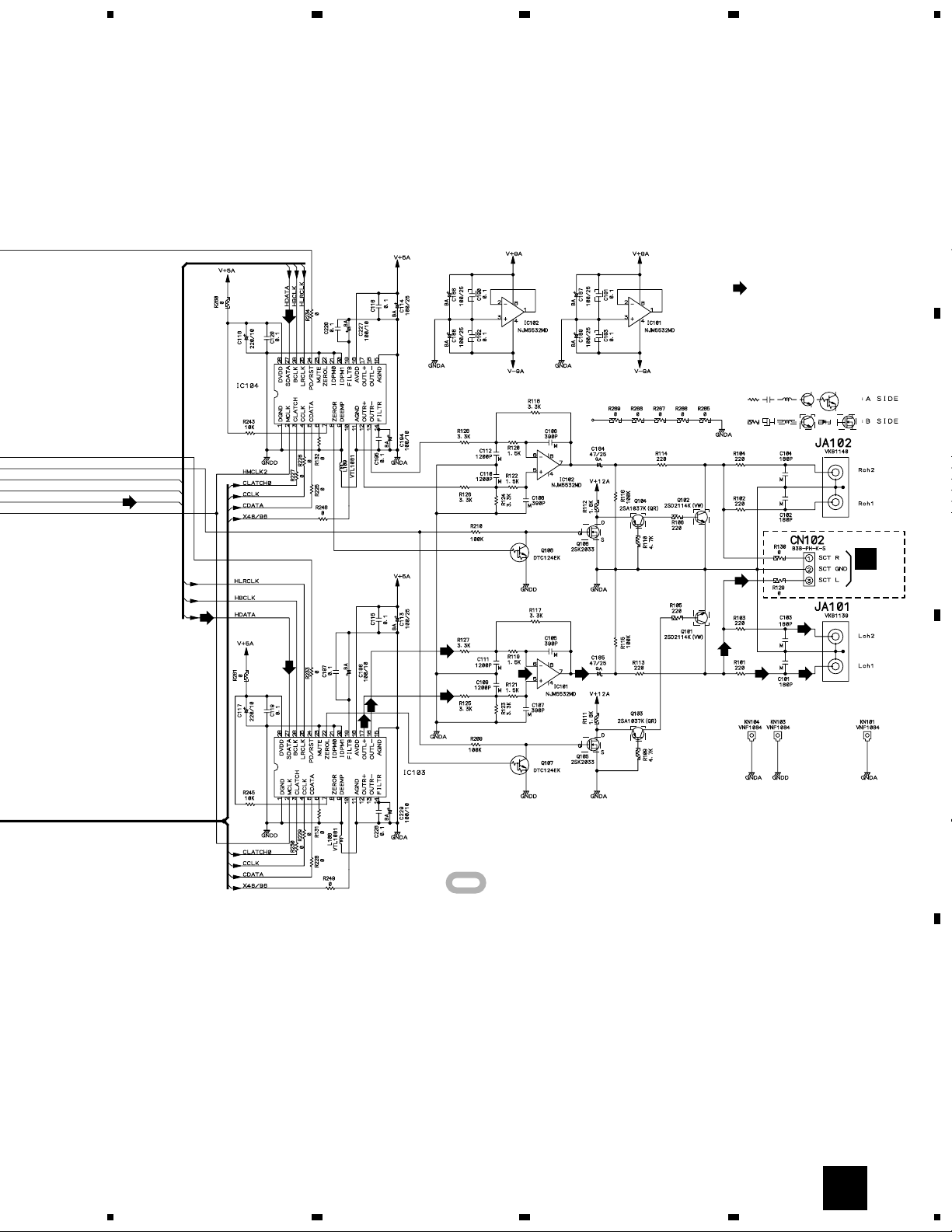
DV-37, DV-S77, DV-S737, DV-737, DV-737-K
27
A
B
C
D
5
678
5
6
7
8
F
AD1854JRS
AD1854JRS
1/2
2/2
2/2
1/2
WY
ONLY
CN402
I
384/256
X2MCLK
48/96
384/256
X2MCLK
48/96
: AUDIO SIGNAL ROUTE
: The power supply is shown with the marked box.
DV-37, DV-S77, DV-S737, DV-737, DV-737-K
28
A
B
C
D
1
23
4
1234
CN104
E 2/5
DJKB ASSY
(KU/CA, LB : VWV1788)
(RL, RL/RD, WY : VWV1789)
G
(D) (D) (D)
G
3.9 DJKB ASSY
DV-37, DV-S77, DV-S737, DV-737, DV-737-K
29
A
B
C
D
5
678
5
6
7
8
G
OPTICAL
COAXIAL
KU/CA, LB
ONLY
RL, RL/RD, WY ONLY
: AUDIO SIGNAL ROUTE (DIGITAL)
(D)
(D) (D)
(D)
(D)
(D)
(D)
(D)
: The power supply is shown with the marked box.
 Loading...