


Service |
DEH-P645/UC |
Manual |
CRT2147 |
|
ORDER NO. |
MULTI-CD CONTROL HIGH POWER CD PLAYER WITH ID-LOGIC TUNER
DEH-P645 UC
DEH-P56 UC
DEH-P545 UC DEH-46 UC DEH-445 UC
DEH-41 UC
-See the separate manual CX-597(CRT1829) for the CD mechanism description, disassembly and circuit description.
-The CD mechanism employed in this model is one of S7 series.
CONTENTS
1. |
SAFETY INFORMATION ............................................ |
2 |
7. |
GENERAL INFORMATION ....................................... |
81 |
2. |
EXPLODED VIEWS AND PARTS LIST ....................... |
3 |
|
7.1 PARTS ................................................................. |
81 |
3. |
SCHEMATIC DIAGRAM ........................................... |
12 |
|
7.1.1 IC................................................................ |
81 |
4. |
PCB CONNECTION DIAGRAM ................................ |
40 |
|
7.1.2 DISPLAY .................................................... |
88 |
5. |
ELECTRICAL PARTS LIST ........................................ |
50 |
|
7.2 DIAGNOSIS ........................................................ |
89 |
6. |
ADJUSTMENT.......................................................... |
75 |
|
7.2.1 DISASSEMBLY ......................................... |
89 |
|
|
|
|
7.2.2 TEST MODE .............................................. |
90 |
|
|
|
|
7.3 BLOCK DIAGRAM .............................................. |
92 |
|
|
|
8. |
OPERATIONS AND SPECIFICATIONS..................... |
94 |
PIONEER ELECTRONIC CORPORATION |
4-1, Meguro 1-Chome, Meguro-ku, Tokyo 153-8654, Japan |
PIONEER ELECTRONICS SERVICE INC. P.O.Box 1760, Long Beach, CA 90801-1760 U.S.A. |
|
PIONEER ELECTRONIC [EUROPE] N.V. Haven 1087 Keetberglaan 1, 9120 Melsele, Belgium
PIONEER ELECTRONICS ASIACENTRE PTE.LTD. 501 Orchard Road, #10-00, Lane Wheelock Place, Singapore 23880
C PIONEER ELECTRONIC CORPORATION 1998
K-FEA. FEB. 1998 Printed in Japan
DEH-P645,P56,P545,46,445,41
- CD Player Service Precautions
1.For pickup unit(CXX1230) handling, please refer to"Disassembly"(CX-597 Service Manual CRT1829). During replacement, handling precautions shall be taken to prevent an electrostatic discharge(protection by a short pin).
2.During disassembly, be sure to turn the power off since an internal IC might be destroyed when a connector is plugged or unplugged.
3.Please checking the grating after changing the service pickup unit(see page 79).
1. SAFETY INFORMATION
CAUTION
This service manual is intended for qualified service technicians; it is not meant for the casual do-it-yourselfer. Qualified technicians have the necessary test equipment and tools, and have been trained to properly and safely repair complex products such as those covered by this manual.
Improperly performed repairs can adversely affect the safety and reliability of the product and may void the warranty. If you are not qualified to perform the repair of this product properly and safely; you should not risk trying to do so and refer the repair to a qualified service technician.
WARNING
Lead in solder used in this product is listed by the California Health and Welfare agency as a known reproductive toxicant which may cause birth defects or other reproductive harm (California Health and Safety Code, Section 25249.5). When servicing or handling circuit boards and other components which contain lead in solder, avoid unprotected skin contact with the solder. Also, when soldering do not inhale any smoke or fumes produced.
2
DEH-P645,P56,P545,46,445,41
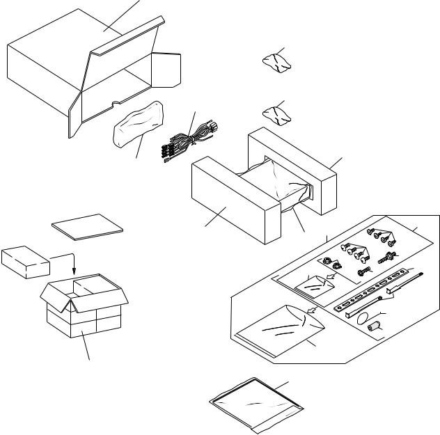
2. EXPLODED VIEWS AND PARTS LIST
2.1 PACKING
18
17
23
2
21
22
20 |
3 |
|
9 |
5 |
|
|
|||
|
16 |
11 |
|
|
|
|
|
|
|
|
10 |
|
7 |
14 |
|
8 |
6 |
|
|
|
|
|
13 |
|
|
|
|
4 |
|
|
|
|
15 |
|
19
1
Fig. 1
3
DEH-P645,P56,P545,46,445,41
NOTE:
-Parts marked by "*"are generally unavailable because they are not in our Master Spare Parts List.
-Screws adjacent to mark on the product are used for disassembly.
-PACKING SECTION PARTS LIST
(1) PARTS LIST
Mark No. Description |
Part No. |
Mark No. Description |
Part No. |
||||
|
|
|
|
|
|
|
|
* |
1-1 |
Card |
See Contrast table(2) |
11 |
Screw |
TRZ50P080FMC |
|
|
1-2 |
Polyethylene Bag |
CEG1116 |
|
* 12 Polyethylene Bag |
CEG-158 |
|
|
1-3 |
Owner's Manual |
See Contrast table(2) |
13 |
Handle |
CNC5395 |
|
|
1-4 |
Installation Manual |
See Contrast table(2) |
14 |
Strap |
CNF-111 |
|
* |
1-5 |
Warranty Card |
See Contrast table(2) |
15 |
Bush |
CNV1009 |
|
|
1-6 |
Caution Card |
See Contrast table(2) |
16 |
Polyethylene Bag |
CEG1173 |
|
|
2 |
Cord Assy |
See Contrast table(2) |
17 |
Battery |
See Contrast table(2) |
|
|
3 |
Accessory Assy |
CEA1918 |
18 |
Carton |
See Contrast table(2) |
|
|
4 |
Spring |
CBH-865 |
19 |
Contain Box |
See Contrast table(2) |
|
|
5 |
Screw Assy |
CEA1924 |
20 |
Protector |
CHP1766 |
|
|
6 |
Screw |
CBA-102 |
21 |
Protector |
CHP1767 |
|
|
7 |
Screw |
CBA1284 |
22 |
Case Assy |
CXB1063 |
|
* |
8 |
Polyethylene Bag |
CNM4338 |
23 |
Remote Control Unit |
See Contrast table(2) |
|
|
9 |
Screw |
CRZ50P090FMC |
|
|
|
|
|
10 |
Nut |
NF50FMC |
|
|
|
|
- Owner’s Manual
Model |
Part No. |
Language |
DEH-P645/UC |
CRD2555 |
English, French |
DEH-P56/UC |
CRD2564 |
English, French |
DEH-P545/UC |
CRD2566 |
English, French, Spanish |
DEH-46/UC |
CRD2572 |
English, French, Spanish |
DEH-445/UC |
CRD2574 |
English, French, Spanish |
DEH-41/UC |
CRD2576 |
English, French, Spanish |
- Installation Manual
Model |
Part No. |
Language |
DEH-P645/UC |
CRD2556 |
English, French |
DEH-P56/UC |
CRD2565 |
English, French |
DEH-P545/UC |
CRD2567 |
English, French, Spanish |
DEH-46/UC |
CRD2573 |
English, French, Spanish |
DEH-445/UC |
CRD2575 |
English, French, Spanish |
DEH-41/UC |
CRD2577 |
English, French, Spanish |
(2) CONTRAST TABLE
DEH-P645/UC, DEH-P56/UC, DEH-P545/UC, DEH-46/UC, DEH-445/UC and DEH-41/UC are constructed
same except for the following:
Mark No. Symbol and Description |
Part No. |
|||
DEH-P645/UC |
DEH-P56/UC |
|||
* |
1-1 |
Card |
ARY1048 |
Not used |
|
1-3 |
Owner's Manual |
CRD2555 |
CRD2564 |
|
1-4 |
Installation Manual |
CRD2556 |
CRD2565 |
* |
1-5 |
Warranty Card |
Not used |
CRY1070 |
|
1-6 |
Caution Card |
CRP1182 |
Not used |
|
17 |
Battery |
CEX1030 |
Not used |
|
18 |
Carton |
CHG3435 |
CHG3439 |
|
19 |
Contain Box |
CHL3435 |
CHL3439 |
|
23 |
Remote Control Unit |
CXB1225 |
Not used |
4
DEH-P645,P56,P545,46,445,41
Mark No. Symbol and Description |
Part No. |
|||
DEH-P645/UC |
DEH-P545/UC |
|||
|
1-3 |
Owner's Manual |
CRD2555 |
CRD2566 |
|
1-4 |
Installation Manual |
CRD2556 |
CRD2567 |
|
1-6 |
Caution Card |
CRP1182 |
Not used |
|
17 |
Battery |
CEX1030 |
Not used |
|
18 |
Carton |
CHG3435 |
CHG3438 |
|
19 |
Contain Box |
CHL3435 |
CHL3438 |
|
23 |
Remote Control Unit |
CXB1225 |
Not used |
|
|
|
|
|
Mark No. Symbol and Description |
Part No. |
|||
DEH-P645/UC |
DEH-46/UC |
|||
* |
1-1 |
Card |
ARY1048 |
Not used |
|
1-3 |
Owner's Manual |
CRD2555 |
CRD2572 |
|
1-4 |
Installation Manual |
CRD2556 |
CRD2573 |
* |
1-5 |
Warranty Card |
Not used |
CRY1070 |
|
1-6 |
Caution Card |
CRP1182 |
Not used |
|
17 |
Battery |
CEX1030 |
Not used |
|
18 |
Carton |
CHG3435 |
CHG3443 |
|
19 |
Contain Box |
CHL3435 |
CHL3443 |
|
23 |
Remote Control Unit |
CXB1225 |
Not used |
|
|
|
|
|
Mark No. Symbol and Description |
Part No. |
|||
DEH-P645/UC |
DEH-445/UC |
|||
|
1-3 |
Owner's Manual |
CRD2555 |
CRD2574 |
|
1-4 |
Installation Manual |
CRD2556 |
CRD2575 |
|
17 |
Battery |
CEX1030 |
Not used |
|
18 |
Carton |
CHG3435 |
CHG3444 |
|
19 |
Contain Box |
CHL3435 |
CHL3444 |
|
23 |
Remote Control Unit |
CXB1225 |
Not used |
|
|
|
|
|
Mark No. Symbol and Description |
Part No. |
|||
DEH-P645/UC |
DEH-41/UC |
|||
|
1-3 |
Owner's Manual |
CRD2555 |
CRD2576 |
|
1-4 |
Installation Manual |
CRD2556 |
CRD2577 |
|
1-6 |
Caution Card |
CRP1182 |
Not used |
|
2 |
Cord Assy |
CDE5483 |
CDE5484 |
|
17 |
Battery |
CEX1030 |
Not used |
|
18 |
Carton |
CHG3435 |
CHG3445 |
|
19 |
Contain Box |
CHL3435 |
CHL3445 |
|
23 |
Remote Control Unit |
CXB1225 |
Not used |
5
DEH-P645,P56,P545,46,445,41
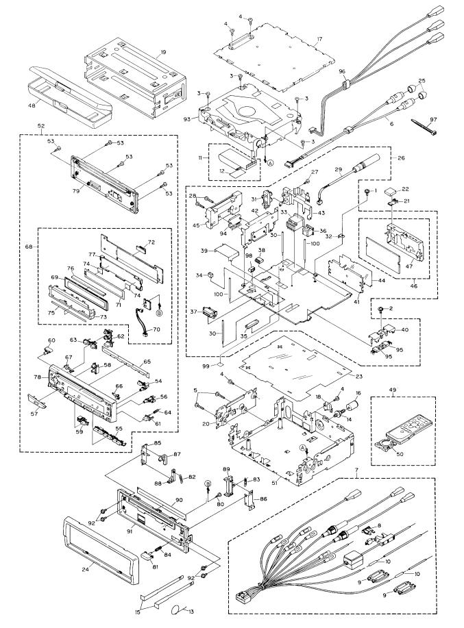
2.2 EXTERIOR
6 |
Fig. 2 |
DEH-P645,P56,P545,46,445,41
- EXTERIOR SECTION PARTS LIST
(1) PARTS LIST
Mark No. Description |
Part No. |
|
Mark No. Description |
Part No. |
||
1 |
Screw |
ASZ26P055FUC |
46 |
FM/AM Tuner Unit |
CWE1417 |
|
2 |
Screw |
ASZ26P080FMC |
47 |
Holder |
CNC6555 |
|
3 |
Screw |
BSZ26P050FMC |
48 |
Case Assy |
CXB1063 |
|
4 |
Screw |
BSZ30P060FMC |
49 |
Remote Control Unit |
See Contrast table(2) |
|
5 |
Screw |
BSZ30P180FMC |
50 |
Cover |
See Contrast table(2) |
|
6 |
Cord Assy |
See Contrast table(2) |
51 |
Chassis Unit |
See Contrast table(2) |
|
7 |
Cord Assy |
See Contrast table(2) |
52 |
Detach Grille Assy |
See Contrast table(2) |
|
8 |
Fuse |
CEK1136 |
53 |
Screw |
BPZ20P100FZK |
|
9 |
Cap |
CNS1472 |
54 |
Button |
CAC5397 |
|
10 |
Resistor |
RS1/2PMF102J |
55 |
Button |
CAC5398 |
|
11 |
Cable |
CDE5635 |
56 |
Button |
CAC5399 |
|
12 |
Insulator |
CNM5761 |
57 |
Button |
CAC5402 |
|
13 |
Spring |
CBH-865 |
58 |
Button |
CAC5403 |
|
14 |
Screw |
CBA1284 |
59 |
Button |
CAC5404 |
|
15 |
Handle |
CNC5395 |
60 |
Button |
CAC5405 |
|
16 |
Bush |
CNV1009 |
61 |
Button |
CAC5430 |
|
17 |
Case |
CNB2119 |
62 |
Button |
CAC5450 |
|
18 |
Holder |
CNC4963 |
63 |
Button |
CAC5451 |
|
19 |
Holder |
CNC6798 |
64 |
Spring |
CBH2103 |
|
20 |
Holder |
CNC6862 |
65 |
Cover |
CNM4704 |
|
21 |
Earth Terminal |
CNC7358 |
66 |
Lighting Conductor |
CNV5180 |
|
22 |
Spacer |
CNM4913 |
67 |
Lighting Conductor |
CNV5181 |
|
23 |
Insulator |
CNM5535 |
68 |
Keyboard Unit |
See Contrast table(2) |
|
24 |
Panel |
CNS4200 |
69 |
LCD |
See Contrast table(2) |
|
25 |
Cap |
See Contrast table(2) |
70 |
Cord |
CDE5665 |
|
26 |
Tuner Amp Unit |
See Contrast table(2) |
71 |
EL |
CEL1536 |
|
27 |
Screw |
BPZ26P080FMC |
72 |
Connector(CN1801) |
CKS3580 |
|
28 |
Screw |
BSZ26P140FMC |
73 |
Holder |
CNC7435 |
|
29 |
Antenna Cord |
CDH1234 |
74 |
Film |
CNM4349 |
|
30 |
Clamper |
CEF1009 |
75 |
Spacer |
CNM5449 |
|
31 |
Pin Jack(CN253) |
CKB1028 |
76 |
Connector |
CNV5182 |
|
32 |
Terminal(CN501) |
CKF1059 |
77 |
Housing |
CNV5183 |
|
33 |
Plug(CN901) |
CKM1278 |
78 |
Grille Unit |
See Contrast table(2) |
|
34 |
Plug(CN802) |
CKS-783 |
79 |
Cover Unit |
CXB2480 |
|
35 |
Connector(CN651) |
CKS2228 |
80 |
Screw |
BPZ20P060FMC |
|
36 |
Connector(CN101) |
See Contrast table(2) |
81 |
Button |
CAC5180 |
|
37 |
Connector(CN801) |
CKS3581 |
82 |
Spring |
CBH1834 |
|
38 |
Connector(CN255) |
See Contrast table(2) |
83 |
Spring |
CBH1835 |
|
39 |
Holder |
CNC5968 |
84 |
Spring |
CBH1996 |
|
40 |
Holder |
CNC6132 |
85 |
Bracket |
CNC6135 |
|
41 |
Holder |
CNC6356 |
86 |
Bracket |
CNC6791 |
|
42 |
Holder |
CNC7429 |
87 |
Arm |
CNV4692 |
|
43 |
Holder |
See Contrast table(2) |
88 |
Arm |
CNV4693 |
|
44 |
Insulator |
CNM4684 |
89 |
Arm |
CNV4951 |
|
45 |
Heat Sink |
CNR1458 |
90 |
Cover |
CNM4875 |
|
7
DEH-P645,P56,P545,46,445,41
Mark No. Description |
Part No. |
|
91 |
Panel |
See Contrast table(2) |
92 |
Screw |
IMS20P030FZK |
93 |
CD Mechanism Module |
CXK5004 |
94 |
IC(IC201) |
See Contrast table(2) |
95 |
Transistor(Q951, 971) |
2SD2396 |
96 |
Cord Assy |
See Contrast table(2) |
97 |
Lock Tie |
See Contrast table(2) |
98 |
Connector(CN851) |
See Contrast table(2) |
99 |
Spacer |
CNM5875 |
100 |
Clamper |
See Contrast table(2) |
(2) CONTRAST TABLE
DEH-P645/UC, DEH-P56/UC, DEH-P545/UC, DEH-46/UC, DEH-445/UC and DEH-41/UC are constructed
same except for the following:
Mark No. Symbol and Description |
Part No. |
||
DEH-P645/UC |
DEH-P56/UC |
||
6 |
Cord Assy |
CDE5208 |
CDE5210 |
25 |
Cap |
CNV2680(×2) |
CNV2680(×4) |
26 |
Tuner Amp Unit |
CWM5620 |
CWM5625 |
38 |
Connector |
CKS3598(CN255) |
CKS3602(CN251) |
43 |
Holder |
CNC7432 |
CNC7431 |
49 |
Remote Control Unit |
CXB1225 |
Not used |
50 |
Cover |
CNS4139 |
Not used |
51 |
Chassis Unit |
CXB1983 |
CXB1982 |
52 |
Detach Grille Assy |
CXB1994 |
CXB2000 |
68 |
Keyboard Unit |
CWM5634 |
CWM5636 |
69 |
LCD |
CAW1479 |
CAW1459 |
78 |
Grille Unit |
CXB1968 |
CXB1973 |
96 |
Cord Assy |
Not used |
CDE5184 |
* 97 |
Lock Tie |
Not used |
CNV-754 |
98 |
Connector(CN851) |
Not used |
CKS3597 |
100 |
Clamper |
Not used |
CEF1009 |
|
|
|
|
Mark No. Symbol and Description |
Part No. |
||
DEH-P645/UC |
DEH-P545/UC |
||
26 |
Tuner Amp Unit |
CWM5620 |
CWM5626 |
49 |
Remote Control Unit |
CXB1225 |
Not used |
50 |
Cover |
CNS4139 |
Not used |
52 |
Detach Grille Assy |
CXB1994 |
CXB2001 |
68 |
Keyboard Unit |
CWM5634 |
CWM5636 |
69 |
LCD |
CAW1479 |
CAW1459 |
78 |
Grille Unit |
CXB1968 |
CXB1974 |
8
DEH-P645,P56,P545,46,445,41
Mark No. Symbol and Description |
Part No. |
||
DEH-P645/UC |
DEH-46/UC |
||
6 |
Cord Assy |
CDE5208 |
CDE5210 |
25 |
Cap |
CNV2680(×2) |
CNV2680(×4) |
26 |
Tuner Amp Unit |
CWM5620 |
CWM5627 |
36 |
Connector(CN101) |
CKS3408 |
Not used |
38 |
Connector |
CKS3598(CN255) |
CKS3602(CN251) |
43 |
Holder |
CNC7432 |
CNC7431 |
49 |
Remote Control Unit |
CXB1225 |
Not used |
50 |
Cover |
CNS4139 |
Not used |
51 |
Chassis Unit |
CXB1983 |
CXB1988 |
52 |
Detach Grille Assy |
CXB1994 |
CXB2003 |
68 |
Keyboard Unit |
CWM5634 |
CWM5640 |
78 |
Grille Unit |
CXB1968 |
CXB1976 |
91 |
Panel |
CNS4451 |
CNS4450 |
94 |
IC(IC201) |
TDA7386 |
TDA7384 |
96 |
Cord Assy |
Not used |
CDE5184 |
* 97 |
Lock Tie |
Not used |
CNV-754 |
98 |
Connector(CN851) |
Not used |
CKS3597 |
100 |
Clamper |
Not used |
CEF1009 |
|
|
|
|
Mark No. Symbol and Description |
Part No. |
||
DEH-P645/UC |
DEH-445/UC |
||
26 |
Tuner Amp Unit |
CWM5620 |
CWM5628 |
36 |
Connector(CN101) |
CKS3408 |
Not used |
49 |
Remote Control Unit |
CXB1225 |
Not used |
50 |
Cover |
CNS4139 |
Not used |
51 |
Chassis Unit |
CXB1983 |
CXB1989 |
52 |
Detach Grille Assy |
CXB1994 |
CXB2004 |
68 |
Keyboard Unit |
CWM5634 |
CWM5640 |
78 |
Grille Unit |
CXB1968 |
CXB1977 |
91 |
Panel |
CNS4451 |
CNS4450 |
94 |
IC(IC201) |
TDA7386 |
TDA7384 |
|
|
|
|
Mark No. Symbol and Description |
Part No. |
||
DEH-P645/UC |
DEH-41/UC |
||
6 |
Cord Assy |
CDE5208 |
Not used |
7 |
Cord Assy |
CDE5483 |
CDE5484 |
25 |
Cap |
CNV2680 |
Not used |
26 |
Tuner Amp Unit |
CWM5620 |
CWM5629 |
36 |
Connector(CN101) |
CKS3408 |
Not used |
38 |
Connector(CN255) |
CKS3598 |
Not used |
43 |
Holder |
CNC7432 |
CNC7434 |
49 |
Remote Control Unit |
CXB1225 |
Not used |
50 |
Cover |
CNS4139 |
Not used |
51 |
Chassis Unit |
CXB1983 |
CXB1989 |
52 |
Detach Grille Assy |
CXB1994 |
CXB2005 |
68 |
Keyboard Unit |
CWM5634 |
CWM5640 |
78 |
Grille Unit |
CXB1968 |
CXB1978 |
91 |
Panel |
CNS4451 |
CNS4869 |
94 |
IC(IC201) |
TDA7386 |
TDA7384 |
9
DEH-P645,P56,P545,46,445,41
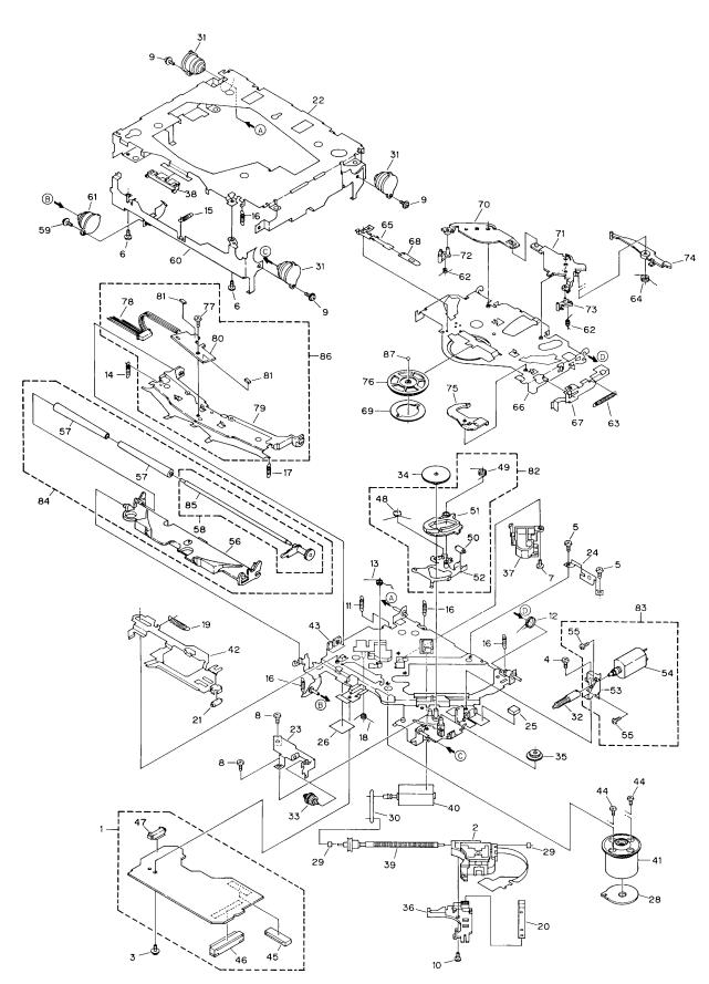
2.3 CD MECHANISM MODULE
Fig. 3
10
DEH-P645,P56,P545,46,445,41
- CD MECHANISM MODULE SECTION PARTS LIST
Mark No. Description |
Part No. |
|
Mark No. Description |
Part No. |
||
|
|
|
|
|
|
|
1 |
Control Unit |
CWX2224 |
46 |
Connector(CN701) |
CKS2774 |
|
2 |
Pickup Unit(Service) |
CXX1230 |
47 |
Connector(CN801) |
CKS2196 |
|
3 |
Screw |
IMS26P035FMC |
48 |
Spring |
CBH1832 |
|
4 |
Screw |
BMZ20P025FMC |
49 |
Spring |
CBH1833 |
|
5 |
Screw |
BMZ20P040FMC |
50 |
Roller |
CLA2627 |
|
6 |
Screw |
BSZ20P040FMC |
51 |
Arm |
CNV4136 |
|
7 |
Screw |
CBA1077 |
52 |
Arm Unit |
CXA8565 |
|
8 |
Screw |
CBA1250 |
53 |
Bracket |
CNC6056 |
|
9 |
Screw |
CBA1296 |
54 |
Load Motor Unit(S7) |
CXA8702 |
|
10 |
Screw |
CBA1362 |
55 |
Screw |
JFZ20P025FMC |
|
11 |
Spring |
CBH1724 |
56 |
Arm |
CNV4120 |
|
12 |
Spring |
CBH1729 |
57 |
Roller |
CNV4509 |
|
13 |
Spring |
CBH1730 |
58 |
Gear Unit(S7) |
CXA8701 |
|
14 |
Spring |
CBH1731 |
59 |
Screw |
CBA1296 |
|
15 |
Spring |
CBH1732 |
60 |
Frame |
CNC5797 |
|
16 |
Spring |
CBH1745 |
61 |
Damper |
CNV3974 |
|
17 |
Spring |
CBH1848 |
62 |
Spring |
CBH1736 |
|
18 |
Spring |
CBH1849 |
63 |
Spring |
CBH1863 |
|
19 |
Spring |
CBH1939 |
64 |
Spring |
CBH1945 |
|
20 |
Spring |
CBL1214 |
65 |
Spring |
CBL1269 |
|
21 |
Roller |
CLA2627 |
66 |
Arm |
CNC5799 |
|
22 |
Frame |
CNC5796 |
67 |
Lever |
CNC6054 |
|
23 |
Bracket |
CNC5871 |
68 |
Spacer |
CNM3315 |
|
* 24 |
Bracket |
CNC6376 |
69 |
Sheet |
CNM4849 |
|
25 |
Cushion |
CNM3917 |
70 |
Arm |
CNV5436 |
|
26 |
Sheet |
CNM4873 |
71 |
Arm |
CNV4123 |
|
27 |
••••• |
|
72 |
Arm |
CNV4124 |
|
28 |
PCB |
CNP4230 |
73 |
Arm |
CNV4125 |
|
29 |
Bearing |
CNR1415 |
74 |
Arm |
CNV4138 |
|
30 |
Belt |
CNT1071 |
75 |
Arm |
CNV4139 |
|
31 |
Damper |
CNV3974 |
76 |
Clamper |
CNV5308 |
|
32 |
Gear |
CNV4128 |
77 |
Screw |
CBA1250 |
|
33 |
Gear |
CNV4129 |
78 |
Connector(CN1) |
CDE4576 |
|
34 |
Gear |
CNV4130 |
79 |
Arm |
CNC7383 |
|
35 |
Gear |
CNV4131 |
|
* 80 Gathering PCB |
CNX2445 |
|
36 |
Holder |
CNV4663 |
81 |
Photo-transistor(Q1, 2) |
CPT-230S-X |
|
37 |
Holder |
CNV5071 |
82 |
ELBO Arm Assy(S7) |
CXA8889 |
|
38 |
Guide |
CNV4484 |
83 |
Load Motor Assy(S7) |
CXA8891 |
|
39 |
Screw Unit(S7) |
CXA8699 |
84 |
LO Arm Assy(S7) |
CXA8892 |
|
40 |
CRG Motor Unit(S7) |
CXA8986 |
85 |
Shaft |
CLA3133 |
|
41 |
Motor Unit |
CXA8912 |
86 |
Guide Arm Assy(S7) |
CXB1850 |
|
42 |
Lever Unit |
CXA9300 |
87 |
Ball |
CNR1189 |
|
43 |
Chassis Unit |
CXB2574 |
|
|
|
|
44 |
Screw |
JFZ20P025FMC |
|
|
|
|
45 |
Connector(CN101) |
CKS1953 |
|
|
|
|
11
|
1 |
|
2 |
|
3 |
|
4 |
|
|
|
|
|
|
DEH-P645,P56,P545,46,445,41
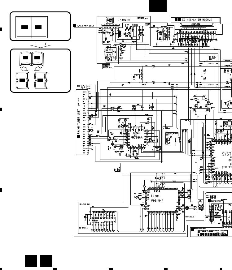
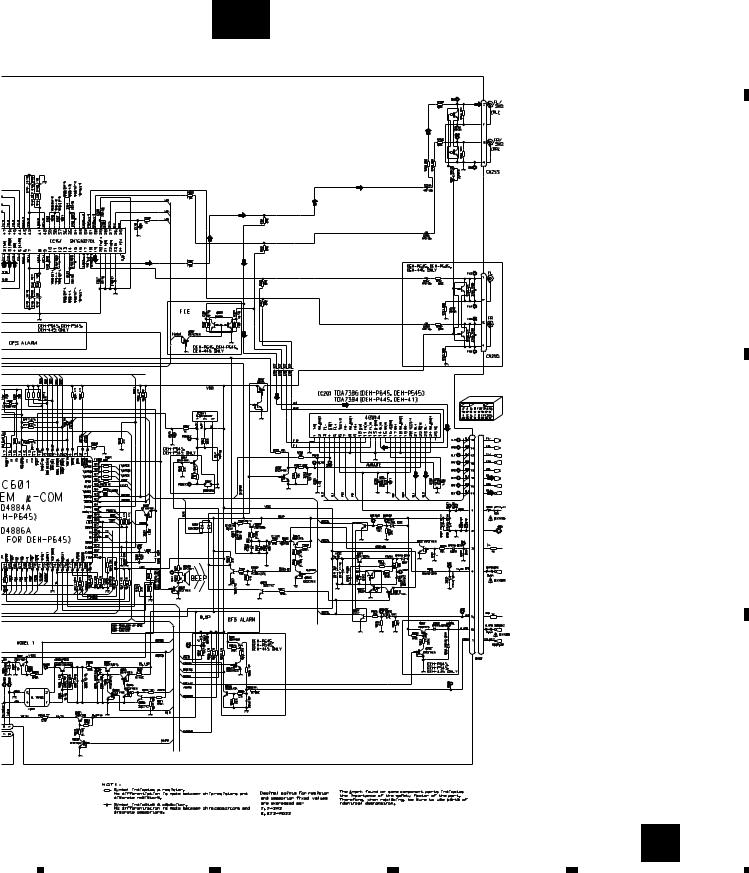
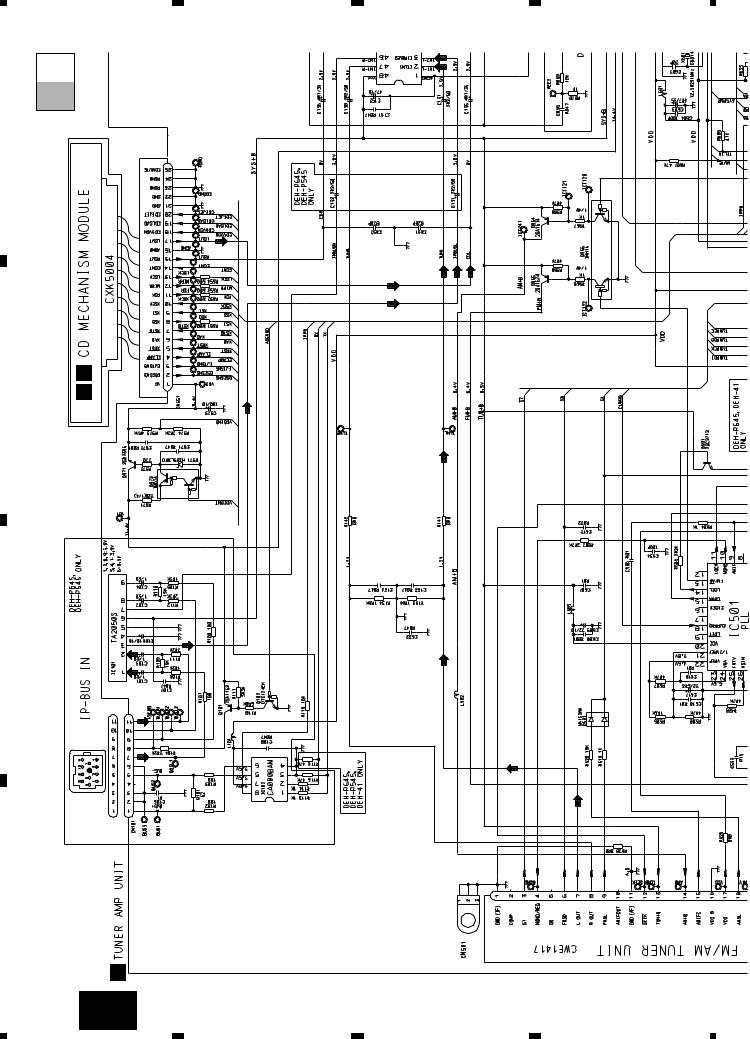
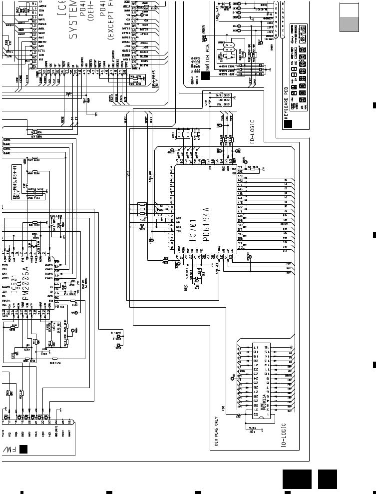
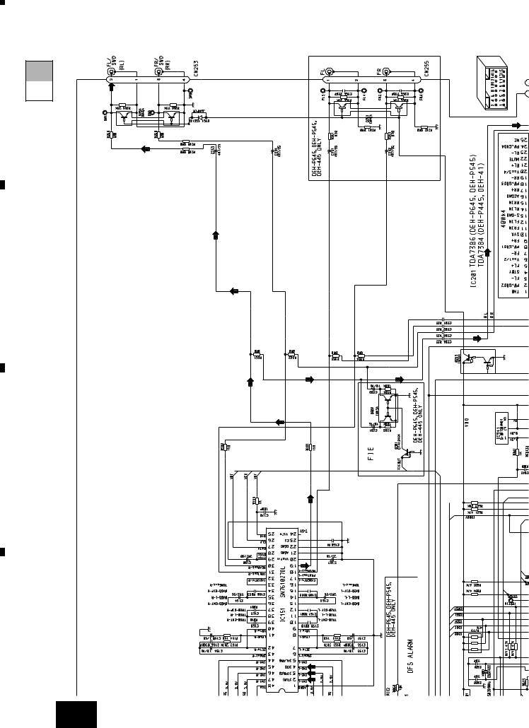
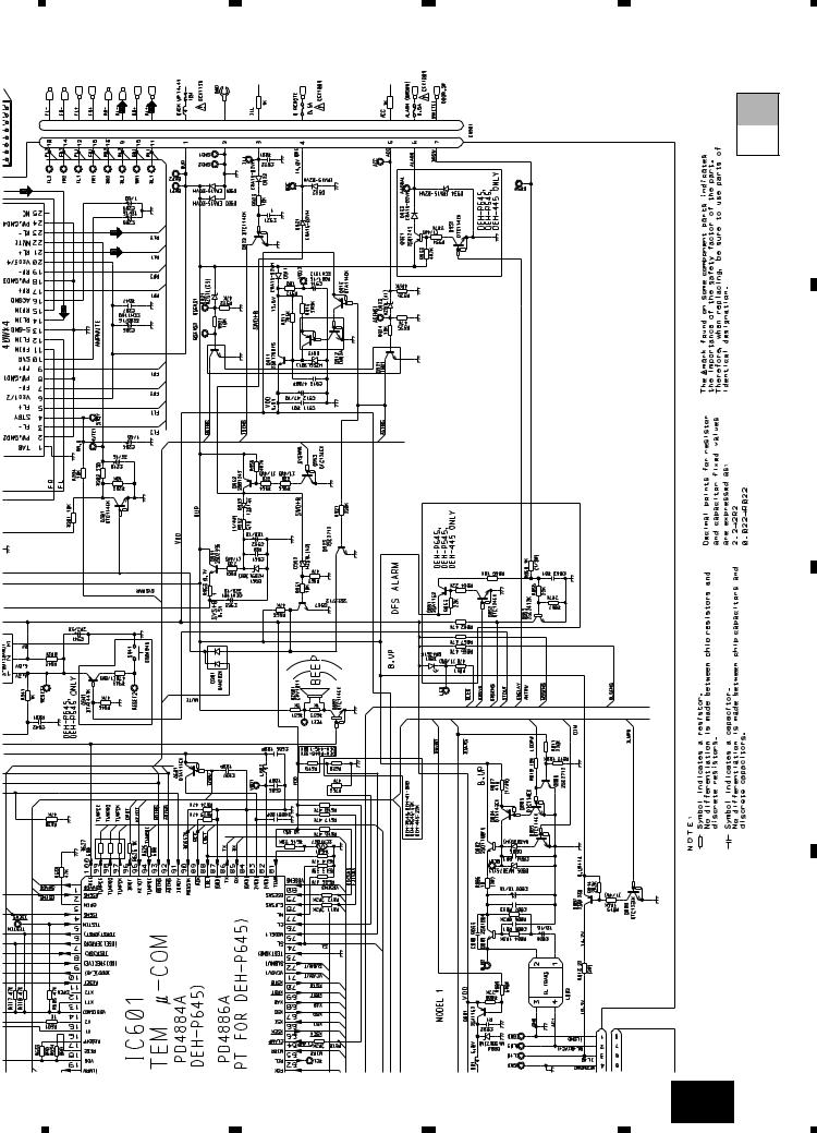
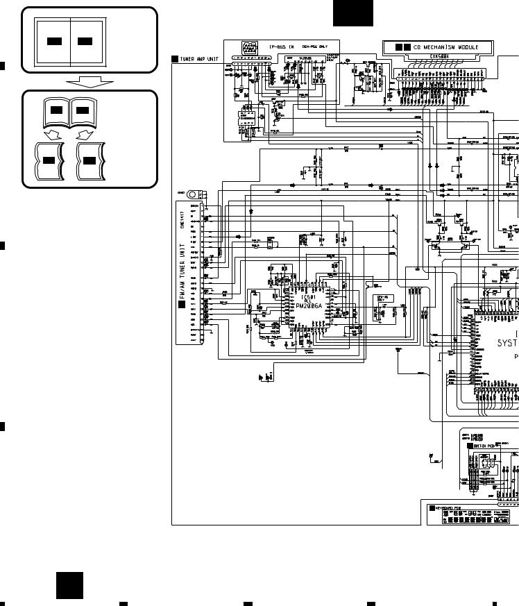
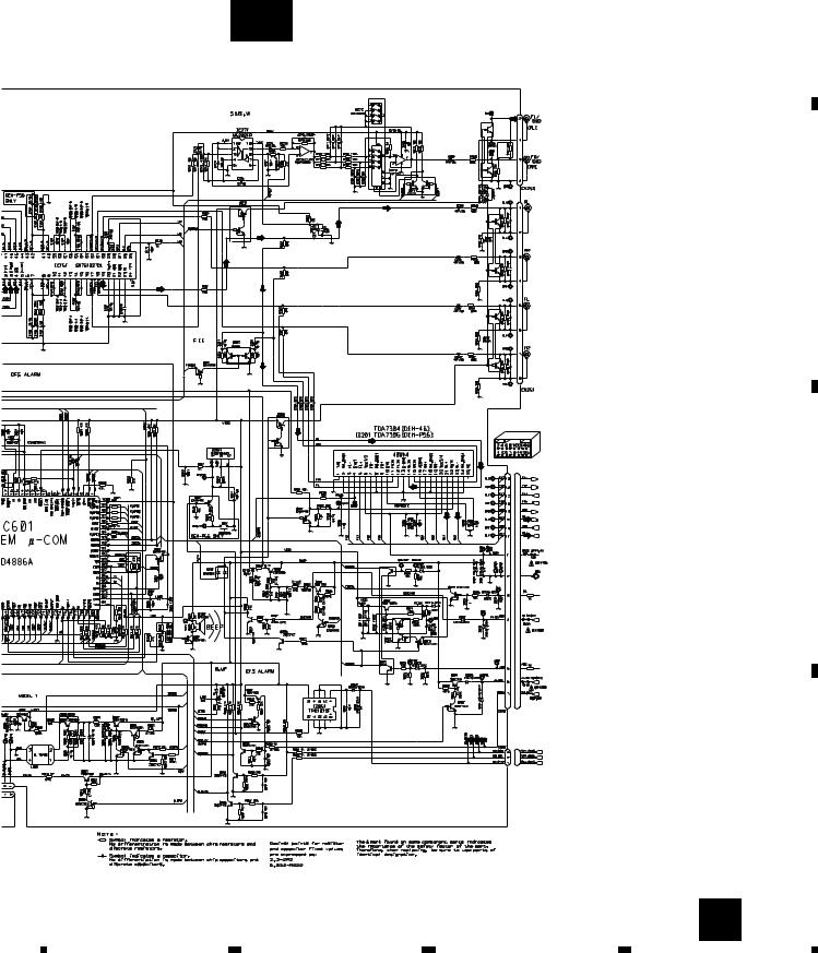
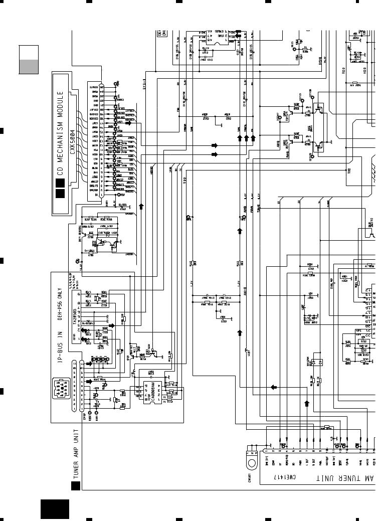
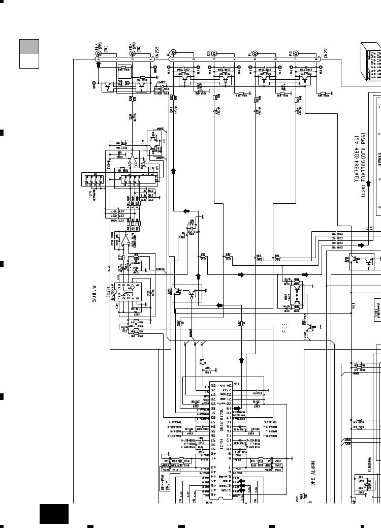
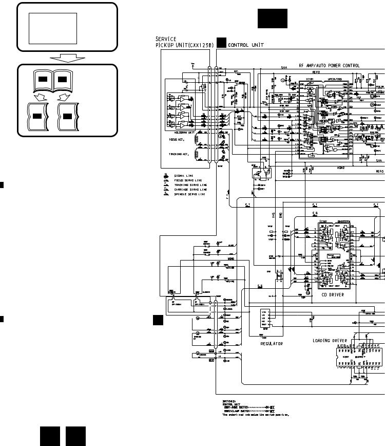
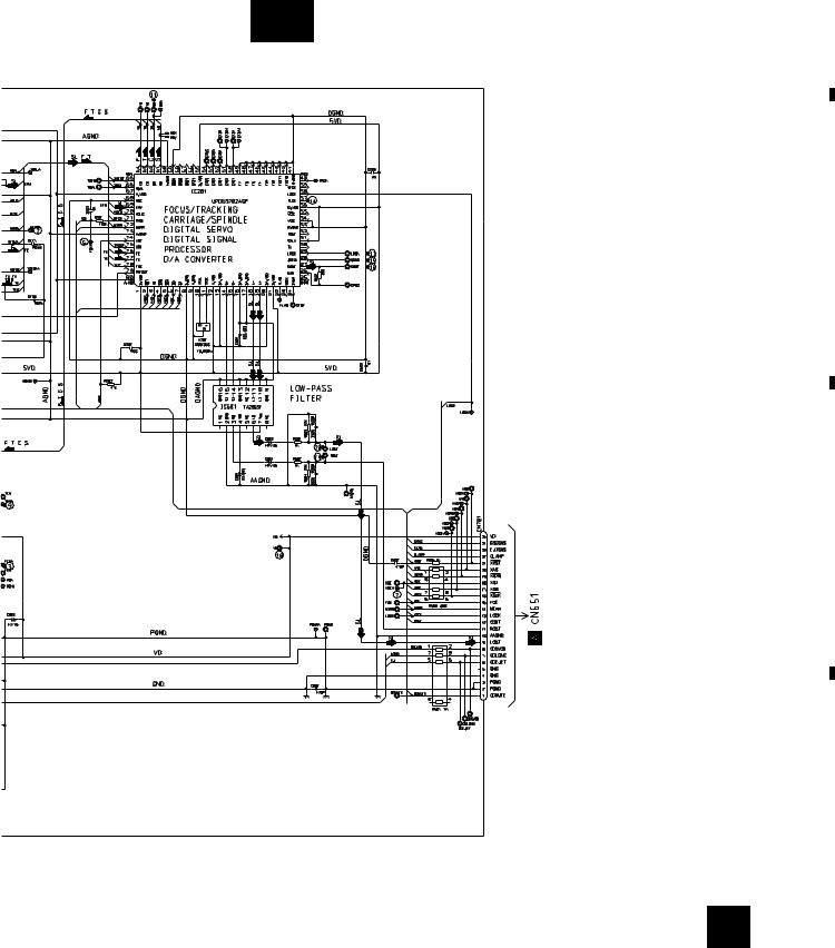
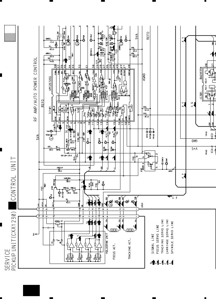
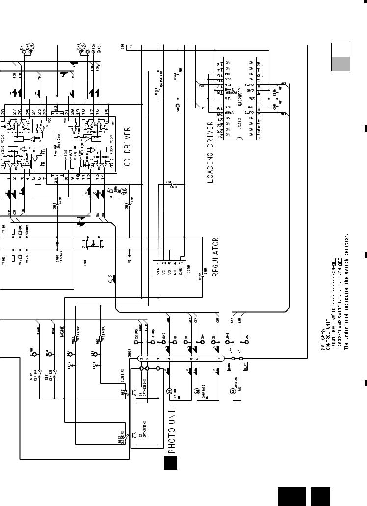
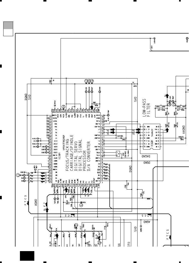
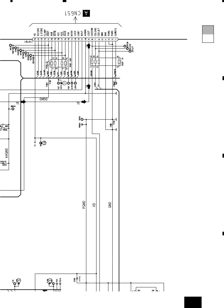
3. SCHEMATIC DIAGRAM
3.1 OVERALL CONNECTION DIAGRAM(GUIDE PAGE)
A
Note: When ordering service parts, be sure to refer to “EXPLODED VIEWS AND PARTS LIST” or “ELECTRICAL PARTS
|
LIST”. |
|
|
|
|
A-a |
- DEH-P645/UC,DEH-P545/UC,DEH-445/UC,DEH-41/UC |
|
|||||
|
|
|
|
|
|
|
|
|
|
Large size |
|
|
D E |
|
|
|
|
|
|
|
|
A-a |
A-b |
SCH diagram |
A |
|
|
|
|
|
|
|
||
|
A-a |
A-b |
Guide page |
|
|
|
B |
|
|
|
|
|
|
|
A-a |
A-b |
Detailed page |
|
|
|
|
|
|
|
B |
|
|
C |
|
|
|
|
|
|
|
|
|
|
|
|
F |
D |
|
|
|
|
|
C |
12 |
A F |
|
|
|
||
|
1 |
|
|
2 |
3 |
4 |
|
5 |
|
6 |
|
7 |
|
8 |
|
|
|
|
|
|
DEH-P645,P56,P545,46,445,41
|
|
|
|
A |
|
A-b |
|
|
|
|
|
|
|
B |
|
|
|
|
C |
|
|
|
|
D |
|
|
|
Fig. 4 |
|
|
|
|
A |
13 |
|
|
|
|
|
5 |
6 |
7 |
8 |
|
|
1 |
2 |
3 |
4 |
DEH-P645,P56,P545,46,445,41 |
|
|
||
A-b |
|
|
|
|
A-a |
|
|
|
|
A |
|
|
|
|
|
E |
|
|
|
B |
D |
|
|
|
C |
|
|
|
|
D |
|
|
|
|
|
A |
|
|
|
14 |
A-a |
|
|
|
|
1 |
2 |
3 |
4 |
|
5 |
|
6 |
|
7 |
|
8 |
|
|
|
|
|
|
DEH-P645,P56,P545,46,445,41
|
|
|
|
A-b |
|
|
|
|
A-a |
|
|
|
|
A |
|
|
F |
|
|
|
|
C |
|
|
|
|
|
|
B |
|
|
|
|
C |
|
|
|
|
D |
B |
|
|
|
|
|
|
|
|
Fig. 5 |
|
|
A-a |
F |
15 |
5 |
6 |
7 |
8 |
|
A
B
C
D
1 |
|
2 |
|
3 |
|
4 |
|
|
|
|
|
DEH-P645,P56,P545,46,445,41
A-a A-b
16 A-b
|
1 |
|
2 |
|
3 |
|
4 |
|
|
|
|
|
|
||||
|
|
|
|
|
5 |
6 |
7 |
8 |
|
|
|
|
DEH-P645,P56,P545,46,445,41 |
|
||
|
|
|
|
A-b |
|
|
|
|
|
A-a |
A |
|
|
|
|
|
B |
|
|
|
|
|
C |
|
|
|
|
|
D |
|
|
|
|
Fig. 6 |
|
|
|
|
A-b |
17 |
|
5 |
6 |
7 |
8 |
|
|
|
1 |
|
2 |
|
3 |
|
4 |
|
|
|
|
|
|
DEH-P645,P56,P545,46,445,41
3.2 OVERALL CONNECTION DIAGRAM(GUIDE PAGE)
- DEH-P56/UC,DEH-46/UC
A
|
|
|
Large size |
|
A-a |
|
A-a |
A-b |
SCH diagram |
|
|
|
|
|
D E |
||
|
|
|
|
|
|
|
|
|
A |
|
|
|
A-a |
A-b |
Guide page |
|
|
B |
A-a |
A-b |
Detailed page |
|
|
|
|
|
|||
|
|
|
B |
|
|
C |
|
|
|
|
|
|
|
|
|
|
F |
|
|
|
|
|
C |
D |
|
|
|
|
|
18 |
A |
|
|
|
|
|
1 |
|
2 |
3 |
4 |
|
5 |
|
6 |
|
7 |
|
8 |
|
|
|
|
|
|
DEH-P645,P56,P545,46,445,41
|
|
|
|
A |
|
A-b |
|
|
|
|
|
|
|
B |
|
|
|
|
C |
|
|
|
|
D |
|
|
|
Fig. 7 |
|
|
|
|
A |
19 |
|
|
|
|
|
5 |
6 |
7 |
8 |
|
|
|
1 |
2 |
3 |
4 |
|
DEH-P645,P56,P545,46,445,41 |
|
|
||
|
A-b |
|
|
|
|
A |
-a |
|
|
|
|
A |
|
|
|
|
|
|
|
|
|
|
|
|
|
E |
|
|
|
B |
|
D |
|
|
|
|
|
|
|
|
|
C |
|
|
|
|
|
D |
|
|
|
|
|
|
|
|
A |
|
|
|
20 |
A-a |
2 |
3 |
4 |
|
|
1 |
|||
|
|
|
|
|
|
|
5 |
|
6 |
|
7 |
|
8 |
|
|
|
|
DEH-P645,P56,P545,46,445,41
F |
A-a A-b
C
B |
|
|
|
|
|
|
|
|
Fig. 8 |
|
|
A-a |
F |
21 |
5 |
6 |
7 |
8 |
|
A
B
C
D
A
1 |
|
2 |
|
3 |
|
4 |
|
|
|
|
|
DEH-P645,P56,P545,46,445,41
A-a A-b
B
C
D
22 A-b
1
2 |
3 |
4 |

|
5 |
|
6 |
|
7 |
|
8 |
|
|
|
|
|
|
DEH-P645,P56,P545,46,445,41
A-a A-b
A
B
|
|
|
|
C |
|
|
|
|
D |
|
|
|
|
Fig. 9 |
|
|
|
A-b |
23 |
5 |
6 |
7 |
8 |
|
|
1 |
|
2 |
|
3 |
|
4 |
|
|
|
|
|
|
DEH-P645,P56,P545,46,445,41
3.3 CD MECHANISM MODULE(GUIDE PAGE)
A
|
|
|
|
|
|
|
|
Large size |
|
|
|
|
|
|
|
|
SCH diagram |
|
|
|
A-a |
|
|
A-b |
|
|
|
|
|
|
|
|
|
||
|
|
|
|
|
|
|
|
|
|
|
|
|
|
|
|
|
|
|
|
|
|
|
|
|
|
|
D-a
D
|
A-a |
A-b |
Guide page |
B |
A-a |
A-b |
Detailed page |
|
|
|
C
22/6R3
E 


CXA8912
BA05SFP
CXA8986
CXA8702
D
24 D E
|
1 |
|
2 |
|
3 |
|
4 |
|
|
|
|
|
|
||||
|
|
|
|
|
|
5 |
|
6 |
|
7 |
|
8 |
|
|
|
|
|
|
DEH-P645,P56,P545,46,445,41
A
D-b
B
C
D
Fig. 10
D 25
|
5 |
|
6 |
|
7 |
|
8 |
|
|
|
|
|
|
||||
|
|
|
|
|
|
|
1 |
2 |
3 |
4 |
|
DEH-P645,P56,P545,46,445,41 |
|
|
||
|
D-b |
|
|
|
|
A |
D-a |
|
|
|
|
B |
|
|
|
|
|
C |
|
|
|
|
|
|
D |
|
|
|
|
D |
|
|
|
|
|
|
26 |
D-a |
|
|
|
|
|
|
|
|
|
|
|
1 |
2 |
3 |
4 |
|
5 |
|
6 |
|
7 |
|
8 |
|
|
|
|
DEH-P645,P56,P545,46,445,41
D-a D-b
22/6R3 |
BA05SFP |
CXA8912 |
CXA8986 |
CXA8702 |
E
Fig. 11
D-a E 27
A
B
C
D
|
5 |
|
6 |
|
7 |
|
8 |
|
|
|
|
|
|
||||
|
|
|
|
|
|
|
1 |
2 |
3 |
4 |
|
DEH-P645,P56,P545,46,445,41 |
|
|
||
|
D-b |
|
|
|
|
A |
D-a |
|
|
|
|
B |
|
|
|
|
|
C |
|
|
|
|
|
D |
|
|
|
|
|
|
28 |
D-b |
|
|
|
|
|
1 |
2 |
3 |
4 |
5 |
6 |
|
7 |
|
8 |
|
|
DEH-P645,P56,P545,46,445,41
D-a D-b
A
B
C
D
Fig. 12
D-b 29
|
5 |
|
6 |
|
7 |
|
8 |
|
|
|
|
|
|
||||
|
|
|
|
|
DEH-P645,P56,P545,46,445,41
|
|
|
|
|
|
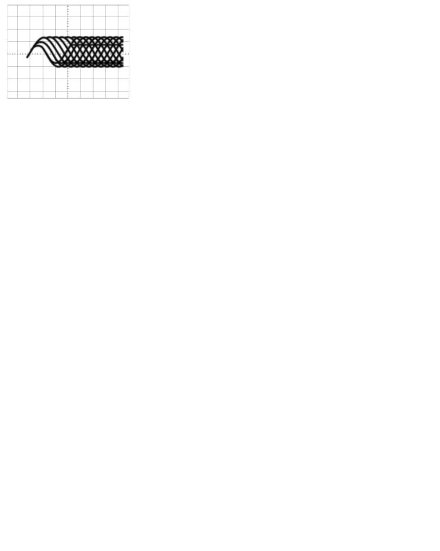
Note:1. The encircled numbers denote measuring pointes in the circuit diagram. |
|||||||||||||||||||||||
- Waveforms |
|
|
|
|
|
|
|
2. Reference voltage |
|
|
|
|
|
|
|
|
|
|
|
|
|
|
|
|
|
||||
|
|
|
|
|
|
|
|
|
REFO:2.5V |
|
|
|
|
|
|
|
|
|
|
|
|
|
|
|
|
|
|
||
|
|
|
|
|
|
|
|
|
|
|
|
|
|
|
|
|
|
|
|
|
|
|
|
|
|
|
|
|
|
1 RFO |
0.5V/div. |
0.5µs/div. |
1 CH1: RFO |
1V/div. |
|
|
|
|
|
|
|
1 CH1: RFO |
1V/div. |
|
|
|
|
|
|
|
|||||||||
0.5ms/div. |
|
|
|
0.5ms/div. |
|||||||||||||||||||||||||
Normal mode: play |
|
|
|
|
|
|
2 CH2: MIRR |
5V/div. |
|
|
|
|
|
|
|
2 CH2: MIRR |
5V/div. |
|
|
|
|
|
|
|
|||||
|
|
|
|
|
|
|
|
|
|
|
|
|
|
|
|
|
|
|
|
||||||||||
|
|
|
|
|
|
|
|
|
Test mode: Tracking open |
Normal mode: The defect part |
|||||||||||||||||||
|
|
|
|
|
|
|
|
|
|
|
|
|
|
|
|
|
|
|
|
|
|
passes 800µm |
|||||||
REFO → |
|
|
|
|
|
|
|
|
|
|
|
|
|
|
|
|
|
|
|
|
|
|
|
|
|
|
|
|
|
|
|
|
|
|
|
|
|
|
|
|
|
|
|
|
|
|
|
|
|
|
|
|
|
|
|
|
|
|
|
|
|
|
|
|
|
|
|
|
|
|
|
|
|
|
|
|
|
|
|
|
|
|
|
|
|
|
|
|
|
|
|
|
|
|
|
|
|
|
GND → |
|
|
|
|
|
|
|
|
|
GND → |
|
|
|
|
|
|
|
|
||
|
|
|
|
|
|
|
|
|
|
|
|
|
|
|
|
|
|
|
|
|
|
|
|
|
|
|
|
|
|
|
|
|
|
|
|
|
|
|
|
|
|
|
|
|
|
|
|
|
|
|
|
|
|
|
|
|
|
|
|
3 CH1: FIN |
0.5V/div. |
|
|
|
|
|
|
3 CH1: FIN |
0.5V/div. |
|
|
|
|
|
|
|
6 CH1: FEY |
0.5V/div. |
|
|
|
|
|
|
|||||
|
|
|
0.2s/div. |
|
|
|
|
|
0.2s/div. |
|
1ms/div. |
||||||||||||||||||
4 CH2: FO+ |
2V/div. |
|
|
|
|
|
|
5 CH2: FOK |
2V/div. |
|
|
|
|
|
|
|
7 CH2: XSI |
2V/div. |
|
|
|
|
|
|
|
||||
|
|
|
|
|
|
|
|
|
|
|
|
|
|
|
|
|
|
|
|
||||||||||
Test mode: No disc, Focus close |
Normal mode: Focus close |
Normal mode: Focus close |
|||||||||||||||||||||||||||
|
|
|
|
|
|
|
|
|
|
|
|
|
|
|
|
|
|
|
|
REFO → |
|
|
|
|
|
|
|
|
|
|
|
|
|
|
|
|
|
|
|
|
|
|
|
|
|
|
|
|
|
|
|
|
|
|
|
|
|
||
REFO → |
|
|
|
|
|
|
|
REFO → |
|
|
|
|
|
|
|
|
|
|
|
|
|
|
|
|
|
|
|
||
REFO → |
|
|
|
|
|
|
|
|
|
|
|
|
|
|
|
|
|
|
REFO → |
|
|
|
|
|
|
|
|
||
|
|
|
|
|
|
|
|
|
REFO → |
|
|
|
|
|
|
|
|
|
GND → |
|
|
|
|
|
|
|
|
||
|
|
|
|
|
|
|
|
|
|
|
|
|
|
|
|
|
|
|
|
|
|
|
|
|
|
|
|
||
|
|
|
|
|
|
|
|
|
GND → |
|
|
|
|
|
|
|
|
|
|
|
|
|
|
|
|
|
|
|
|
|
|
|
|
|
|
|
|
|
|
|
|
|
|
|
|
|
|
|
|
|
|
|
|
|
|
|
|
|
|
|
|
|
|
|
|
|
|
|
|
|
|
|
|
|
|
|
|
|
|
|
|
|
|
|
|
|
|
|
|
8 CH1: TEY |
0.5V/div. |
|
|
|
|
|
8 CH1: TEY |
0.5V/div. |
|
|
|
|
|
|
8 CH1: TEY |
0.5V/div. |
|
|
|
|
|
|
|||||||
|
0.5ms/div. |
0.5ms/div. |
|
|
5ms/div. |
||||||||||||||||||||||||
9 CH2: TIN |
0.5V/div. |
|
|
|
|
|
|
9 CH2: TIN |
0.5V/div. |
|
|
|
|
|
|
|
9 CH2: TIN |
0.5V/div. |
|
|
|
|
|
|
|
||||
|
|
|
|
|
|
|
|
|
|
|
|
|
|
|
|
|
|
|
|
||||||||||
Test mode: 32 tracks jump (FWD) |
Test mode: Single jump (FWD) |
Test mode: 100 tracks jump (FWD) |
|||||||||||||||||||||||||||
REFO → |
|
|
|
|
|
|
|
REFO → |
|
|
|
|
|
|
|
|
REFO → |
|
|
|
|
|
|
|
|
||||
REFO → |
|
|
|
|
|
|
|
REFO → |
|
|
|
|
|
|
|
|
REFO → |
|
|
|
|
|
|
|
|
||||
|
|
|
|
|
|
|
|
|
|
|
|
|
|
|
|
|
|
|
|
|
|
|
|
|
|
|
|
|
|
6 CH1: FEY |
0.1V/div. |
|
|
|
|
|
3 CH1: FIN |
0.5V/div. |
|
|
|
|
|
3 CH1: FIN |
0.5V/div. |
|
|
|
|
|
|||||||||
|
|
20ms/div. |
|
0.5s/div. |
|||||||||||||||||||||||||
|
|
|
|
|
|
|
|
0.5s/div. |
|||||||||||||||||||||
3 CH2: FIN |
0.2V/div. |
|
|
|
|
|
|
0 CH2: SIN |
1V/div. |
|
|
|
|
|
|
|
0 CH2: SIN |
1V/div. |
|
|
|
|
|
|
|
||||
|
|
|
|
|
|
|
|
|
|
|
|
|
|
|
|
|
|
|
|
||||||||||
Normal mode: Play |
|
|
|
|
|
|
Normal mode: Focus close (12cm) |
Normal mode: Focus close (8cm) |
|||||||||||||||||||||
REFO → |
|
|
|
|
|
|
|
REFO → |
|
|
|
|
|
|
|
|
|
REFO → |
|
|
|
|
|
|
|
|
|
||
|
|
|
|
|
|
|
|
|
|
|
|
|
|
|
|
|
|
|
|
|
|
|
|
|
|||||
REFO → |
|
|
|
|
|
|
|
REFO → |
|
|
|
|
|
|
|
|
REFO → |
|
|
|
|
|
|
|
|
|
|||
|
|
|
|
|
|
|
|
|
|
|
|
|
|
|
|
|
|
|
|
|
|
|
|
|
|
|
|
|
|
30
 Loading...