


ORDER NO.
RRV3353
CDJ-1000MK3
COMPACT DISC PLAYER
CDJ-1000MK3
THIS MANUAL IS APPLICABLE TO THE FOLLOWING MODEL(S) AND TYPE(S).
Model |
Type |
|
|
Power Requirement |
Remarks |
||||
|
|
|
|
|
|
|
|
|
|
CDJ-1000MK3 |
KUCXJ |
AC 120V |
|
||||||
|
|
|
|
|
|
|
|
|
|
CDJ-1000MK3 |
WYXJ5 |
AC 220-240V |
|
||||||
|
|
|
|
|
|
|
|
|
|
CDJ-1000MK3 |
TLFXJ |
AC 110-240V |
|
||||||
|
|
|
|
|
|
|
|
|
|
|
|
|
|
|
|
|
|
|
|
|
|
|
|
|
|
|
|
|
|
|
|
|
|
|
|
|
|
|
|
|
|
|
|
|
|
|
|
|
|
|
|
|
|
|
|
|
|
|
|
For details, refer to "Important Check Points for good servicing".

1 |
2 |
3 |
4 |
SAFETY INFORMATION
A
This service manual is intended for qualified service technicians ; it is not meant for the casual do-it- yourselfer. Qualified technicians have the necessary test equipment and tools, and have been trained to properly and safely repair complex products such as those covered by this manual.
Improperly performed repairs can adversely affect the safety and reliability of the product and may void the warranty. If you are not qualified to perform the repair of this product properly and safely, you should not risk trying to do so and refer the repair to a qualified service technician.
WARNING
B
This product contains lead in solder and certain electrical parts contain chemicals which are known to the state of California to cause cancer, birth defects or other reproductive harm.
Health & Safety Code Section 25249.6 - Proposition 65
NOTICE
(FOR CANADIAN MODEL ONLY)
Fuse symbols 

 (fast operating fuse) and/or

 (slow operating fuse) on PCB indicate that replacement parts must be of identical designation.
REMARQUE |
|
|
(POUR MODÈLE CANADIEN SEULEMENT) |
|
|
Les symboles de fusible |
(fusible de type rapide) et/ou |
(fusible de type lent) sur CCI indiquent que les pièces |
C de remplacement doivent avoir la même désignation.
(FOR USA MODEL ONLY)
1. SAFETY PRECAUTIONS
The following check should be performed for the continued protection of the customer and service technician.
LEAKAGE CURRENT CHECK
Measure leakage current to a known earth ground (water pipe, conduit, etc.) by connecting a leakage
Dcurrent tester such as Simpson Model 229-2 or equivalent between the earth ground and all exposed metal parts of the appliance (input/output terminals, screwheads, metal overlays, control shaft, etc.). Plug the AC line cord of the appliance directly into a 120V AC 60 Hz outlet and turn the AC power switch on. Any current measured must not exceed 0.5 mA.
|
|
|
|
|
|
|
|
|
|
|
Reading should |
||||
|
|
|
|
Leakage |
not be above |
||||||||||
E |
|
|
Device |
current |
0.5 mA |
||||||||||
|
|
|
|
|
|
|
|||||||||
|
|
|
under |
tester |
|
|
|
|
|
||||||
|
|
|
test |
|
|
|
|
|
|
|
|
|
|
|
|
|
|
|
|
|
|
|
|
|
|
|
|
|
|
|
|
|
|
|
Test all |
|
|
|
|
|
|
|
|
|
|
|
|
|
|
|
exposed metal |
|
|
|
|
|
|
|
|
|
|
|
|
|
|
|
surfaces |
|
|
|
|
|
|
|
|
|
|
|
|
|
|
|
Also test with |
|
|
|
|
|
|
|
|
|
|
|
|
|
|
|
|
|
|
|
|
|
|
|
|
|
|
|
|
|
|
|
plug reversed |
|
|
|
|
|
|
|
|
|
|
|
Earth |
|
|
|
|
|
|
|
|
|
|
|
|
||||
|
|
|
(Using AC adapter |
|
|
|
|
|
|
|
|
|
|
|
ground |
|
|
|
plug as required) |
|
|
|
|
|
|
|
|
|
|
|
|
F |
|
|
AC Leakage Test |
|
|
|
|
|
|||||||
|
|
|
|
|
|
|
|
|
|
|
|
|
|
|
|
ANY MEASUREMENTS NOT WITHIN THE LIMITS OUTLINED ABOVE ARE INDICATIVE OF A POTENTIAL SHOCK HAZARD AND MUST BE CORRECTED BEFORE RETURNING THE APPLIANCE TO THE CUSTOMER.
2. PRODUCT SAFETY NOTICE
Many electrical and mechanical parts in the appliance have special safety related characteristics. These are often not evident from visual inspection nor the protection afforded by them necessarily can be obtained by using replacement components rated for voltage, wattage, etc. Replacement parts which have these special safety characteristics are identified in this Service Manual.
Electrical components having such features are identified by marking with a > on the schematics and on the parts list in this Service Manual.
The use of a substitute replacement component which does not have the same safety characteristics as the PIONEER recommended replacement one, shown in the parts list in this Service Manual, may create shock, fire, or other hazards.
Product Safety is continuously under review and new instructions are issued from time to time. For the latest information, always consult the current PIONEER Service Manual. A subscription to, or additional copies of, PIONEER Service Manual may be obtained at a nominal charge from PIONEER.
2 |
CDJ-1000MK3 |
1 |
2 |
3 |
4 |

5 |
6 |
7 |
8 |
A
|
IMPORTANT |
|
|
|
LASER DIODE CHARACTERISTICS |
|
|
|
|
|
|
||
|
|
|
|
MAXIMUM OUTPUT POWER : 5 mW |
||
THIS PIONEER APPARATUS CONTAINS |
|
|||||
|
WAVELENGTH : 780 – 785 nm |
|||||
LASER OF CLASS 1. |
|
|||||
|
|
|
|
|||
SERVICING OPERATION OF THE APPARATUS |
|
|
|
|
||
|
|
|
||||
S H O U L D B E D O N E B Y A S P E C I A L LY |
|
|
|
|
||
INSTRUCTED PERSON. |
|
|
|
|
||
|
|
|
|
|
|
|
WARNING !
THE AEL (ACCESSIBLE EMISSION LEVEL) OF THE LASER POWER OUTPUT IS LESS THAN CLASS 1
BUT THE LASER COMPONENT IS CAPABLE OF EMITTING RADIATION EXCEEDING THE LIMIT FOR
CLASS 1.
A SPECIALLY INSTRUCTED PERSON SHOULD DO SERVICING OPERATION OF THE APPARATUS.
B
LABEL CHECK
for WYXJ5 and KUCXJ types |
for TLFXJ type |
|
|
|
|
C
(DRW2308)
(DRW2248)
D
(Printed on the bottom plate) |
Additional Laser Caution
1.Laser Interlock Mechanism
The position of the switch (S2401) for detecting loading completion is detected by the system microprocessor, and the design prevents laser diode oscillation when the switch is not in LPS1 terminal side (when the mechanism is not clamped and LPS1 signal is high level.)
Thus, the interlock will no longer function if the switch is deliberately set to LPS1 terminal side. ( if LPS1 signal is low
level ).
In the test mode the interlock mechanism will not function. Laser diode oscillation will continue, if pin 5 of AN22022A
(IC601) on the MAIN Assy is connected to GND, or else the terminals of Q603 are shorted to each other (fault condition).
2.When the cover is opened, close viewing of the objective lens with the naked eye will cause exposure to a Class 1 laser beam.
|
|
|
|
|
|
3 |
|
|
CDJ-1000MK3 |
7 |
|||
|
|
|
||||
5 |
6 |
|
|
|
8 |
|
E
F

1 |
2 |
3 |
4 |
A |
[Important Check Points for Good Servicing] |
|
|
|
In this manual, procedures that must be performed during repairs are marked with the below symbol. |
|
Please be sure to confirm and follow these procedures. |
1. Product safety
Please conform to product regulations (such as safety and radiation regulations), and maintain a safe servicing environment by following the safety instructions described in this manual.
1 Use specified parts for repair.
Use genuine parts. Be sure to use important parts for safety.
2 Do not perform modifications without proper instructions.
B
Please follow the specified safety methods when modification(addition/change of parts) is required due to interferences such as radio/TV interference and foreign noise.
3 Make sure the soldering of repaired locations is properly performed.
When you solder while repairing, please be sure that there are no cold solder and other debris.
Soldering should be finished with the proper quantity. (Refer to the example)
4 Make sure the screws are tightly fastened.
Please be sure that all screws are fastened, and that there are no loose screws.
5 Make sure each connectors are correctly inserted.
Please be sure that all connectors are inserted, and that there are no imperfect insertion.
C
6 Make sure the wiring cables are set to their original state.
Please replace the wiring and cables to the original state after repairs.
In addition, be sure that there are no pinched wires, etc.
7 Make sure screws and soldering scraps do not remain inside the product.
Please check that neither solder debris nor screws remain inside the product.
8 There should be no semi-broken wires, scratches, melting, etc. on the coating of the power cord.
Damaged power cords may lead to fire accidents, so please be sure that there are no damages.
If you find a damaged power cord, please exchange it with a suitable one.
9 There should be no spark traces or similar marks on the power plug.
D
When spark traces or similar marks are found on the power supply plug, please check the connection and advise on secure connections and suitable usage. Please exchange the power cord if necessary.
0 Safe environment should be secured during servicing.
When you perform repairs, please pay attention to static electricity, furniture, household articles, etc. in order to prevent injuries.
Please pay attention to your surroundings and repair safely.
|
2. Adjustments |
|
|
To keep the original performance of the products, optimum adjustments and confirmation of characteristics within specification. |
|
|
Adjustments should be performed in accordance with the procedures/instructions described in this manual. |
|
E |
3. Lubricants, Glues, and Replacement parts |
|
|
Use grease and adhesives that are equal to the specified substance. |
|
|
Make sure the proper amount is applied. |
|
|
4. Cleaning |
|
|
For parts that require cleaning, such as optical pickups, tape deck heads, lenses and mirrors used in projection monitors, proper |
|
|
cleaning should be performed to restore their performances. |
|
|
5. Shipping mode and Shipping screws |
|
F |
To protect products from damages or failures during transit, the shipping mode should be set or the shipping screws should be |
|
installed before shipment. Please be sure to follow this method especially if it is specified in this manual. |
||
|
||
4 |
CDJ-1000MK3 |
1 |
2 |
3 |
4 |

5 |
6 |
7 |
8 |
CONTENTS |
|
|
|
1. SPECIFICATIONS ............................................................................................................................................. |
|
|
6 |
2. EXPLODED VIEWS AND PARTS LIST............................................................................................................. |
|
|
8 |
2.1 PACKING SECTION ................................................................................................................................... |
|
|
8 |
2.2 EXTERIOR SECTION .............................................................................................................................. |
|
|
10 |
2.3 CONTROL PANEL SECTION................................................................................................................... |
|
|
12 |
2.4 SLOT-IN MECHA. SECTION .................................................................................................................... |
|
|
14 |
2.5 TRAVERSE MECHA. ASSY-S .................................................................................................................. |
|
|
16 |
3. BLOCK DIAGRAM AND SCHEMATIC DIAGRAM .......................................................................................... |
|
18 |
|
3.1 BLOCK DIAGRAM.................................................................................................................................... |
|
|
18 |
3.1.1 SIGNAL SECTION ............................................................................................................................. |
|
|
18 |
3.1.2 POWER SUPPLY SECTION .............................................................................................................. |
|
|
20 |
3.2 OVERALL WIRING DIAGRAM ................................................................................................................. |
|
|
22 |
3.3 MAIN ASSY (1/4)...................................................................................................................................... |
|
|
24 |
3.4 MAIN ASSY (2/4)...................................................................................................................................... |
|
|
26 |
3.5 MAIN ASSY (3/4)...................................................................................................................................... |
|
|
28 |
3.6 MAIN (4/4) and SLMB ASSYS.................................................................................................................. |
|
|
30 |
3.7 SPCN, INSW and SDCB ASSYS ............................................................................................................. |
|
|
32 |
3.8 MJCB ASSY ............................................................................................................................................. |
|
|
34 |
3.9 MFLB ASSY.............................................................................................................................................. |
|
|
36 |
3.10 SLDB and RSWB ASSYS....................................................................................................................... |
|
|
38 |
3.11 JFLB, KSWB and JOGB ASSYS ............................................................................................................ |
|
|
40 |
3.12 SW POWER SUPPLY ASSY .................................................................................................................. |
|
|
42 |
3.13 WAVEFORMS......................................................................................................................................... |
|
|
44 |
3.14 VOLTAGES.............................................................................................................................................. |
|
|
53 |
4. PCB CONNECTION DIAGRAM ...................................................................................................................... |
|
|
55 |
4.1 MAIN ASSY .............................................................................................................................................. |
|
|
56 |
4.2 SLMB, SPCN, INSW and SDCB ASSYS.................................................................................................. |
|
60 |
|
4.3 MJCB ASSY ............................................................................................................................................. |
|
|
62 |
4.4 MFLB and RSWB ASSYS ........................................................................................................................ |
|
|
64 |
4.5 SLDB ASSY.............................................................................................................................................. |
|
|
68 |
4.6 KSWB ASSY............................................................................................................................................. |
|
|
69 |
4.7 JFLB and JOGB ASSYS........................................................................................................................... |
|
|
70 |
4.8 SW POWER SUPPLY ASSY .................................................................................................................... |
|
|
72 |
5. PCB PARTS LIST ............................................................................................................................................ |
|
|
73 |
6. ADJUSTMENT ................................................................................................................................................ |
|
|
77 |
6.1 TEMPO ZERO POINT ADJUSTMENT ..................................................................................................... |
|
|
77 |
6.2 MODE FOR CHECKING THE LOAD ON THE JOG DIAL........................................................................ |
|
78 |
|
7. GENERAL INFORMATION ............................................................................................................................. |
|
|
79 |
7.1 DIAGNOSIS.............................................................................................................................................. |
|
|
79 |
7.1.1 SERVICE MODE ................................................................................................................................ |
|
|
79 |
7.1.2 HOW TO UPGRADE THE SOFTWARE OF THE MICROCOMPUTER |
.............................................87 |
||
7.1.3 SEQUENCE ....................................................................................................................................... |
|
|
88 |
7.1.4 DISASSEMBLY .................................................................................................................................. |
|
|
90 |
7.2 PARTS ...................................................................................................................................................... |
|
|
99 |
7.2.1 IC........................................................................................................................................................ |
|
|
99 |
8. PANEL FACILITIES ....................................................................................................................................... |
|
|
113 |
8.1 PANEL SECTION ................................................................................................................................... |
|
|
113 |
8.2 DISPLAY SECTION ................................................................................................................................ |
|
|
115 |
A
B
C
D
E
F
|
|
|
|
|
|
5 |
|
|
CDJ-1000MK3 |
7 |
|||
|
|
|
||||
5 |
6 |
|
|
|
8 |
|

|
1 |
2 |
|
|
1. SPECIFICATIONS |
||
A |
1. General |
|
|
|
|
||
|
System .......................... |
Compact disc digital audio system |
|
|
Power requirements .......... |
AC 120 V, 60 Hz (KUCXJ type) |
|
|
AC 220 V to 240V, 50/60 Hz (WYXJ5 type) |
||
|
AC 110 V to 240V, 50/60 Hz (TLFXJ type) |
||
|
Power consumption ............................. |
28 W (KUCXJ type) |
|
|
|
27 W (WYXJ5 type) |
|
|
|
27 W (TLFXJ type) |
|
|
Operating temperature ................................ |
+5 ºC to +35 ºC |
|
|
Operating humidity ........................................... |
5 % to 85 % |
|
B |
(There should be no condensation of moisture.) |
||
Weight |
4.2 kg (9.26 lb) |
||
|
|||
|
Dimensions ...................... |
320 (W) x 370 (D) x 105 (H) mm |
|
|
12 - 5/8 (W) x 14 - 9/16 (D) x 4 - 1/8 (H) in |
||
3 |
4 |
3. Accessories |
|
¶ Operating instructions .................................................... |
1 |
¶ Power cord (KUCXJ and WYXJ5 types) ........................ |
1 |
¶ Power cord (TLFXJ type) ............................................... |
2 |
¶ Audio cable .................................................................... |
1 |
¶ Control cord ................................................................... |
1 |
¶ Forced eject pin |
|
(housed in a groove in the bottom panel) ....................... |
1 |
¶ SD memory card ............................................................ |
1 |
¶ Limited warranty (KUCXJ only)....................................... |
1 |
NOTE:
Specifications and design are subject to possible modification without notice.
2. Audio section
Frequency response |
.................................... 4 Hz to 20 kHz |
Signal-to-noise ratio ....................... |
115 dB or more (JEITA) |
Distortion ................................................... |
0.006 % (JEITA) |
C
Accessories |
|
|
|
||
Audio Cable |
Control Cord |
Power Cord |
Forced Eject Pin |
SD Memory Card |
|
(KUCXJ type : ADG7021) |
|||||
(VDE1064) L=1.5m |
(XDE3063) L=1 m |
(DEX1013) |
(DWX2622) |
||
(WYXJ5 : ADG1154) |
|||||
|
|
|
|
||
(TLFXJ type : ADG1154, ADG7097)
D
AC power cord for TLFXJ type
The type of cord which can be used depends on the power voltage in each region or country. Please make sure you use the correct cord due to the possibility of fire or other hazard if used incorrectly (see below).
AC power cord and converter plug use
E Region Plug type
ADG1154
For European type region
Caution
Do not use this power cord set in Taiwan.
|
European two-pin plug |
ADG7097 |
|
For Taiwan exclusively |
|
Caution |
|
For use in Taiwan only. |
|
In other areas, please do not use. |
Taiwanese two-pin flat-bladed plug |
F |
|
6 |
CDJ-1000MK3 |
1 |
2 |
3 |
4 |

5 |
6 |
7 |
8 |
A
B
C
D
E
F
|
|
|
|
|
|
7 |
|
|
CDJ-1000MK3 |
7 |
|||
|
|
|
||||
5 |
6 |
|
|
|
8 |
|
|
1 |
2 |
3 |
4 |
2. EXPLODED VIEWS AND PARTS LIST |
|
|||
NOTES: |
Parts marked by "NSP" are generally unavailable because they are not in our Master Spare Parts List. |
|
||
|
The |
mark found on some component parts indicates the importance of the safety factor of the part. |
|
|
A |
Therefore, when replacing, be sure to use parts of identical designation. |
|
|
|
|
Screws adjacent to mark on product are used for disassembly. |
|
|
|
|
For the applying amount of lubricants or glue, follow the instructions in this manual. |
|
||
|
(In the case of no amount instructions, apply as you think it appropriate.) |
|
|
|
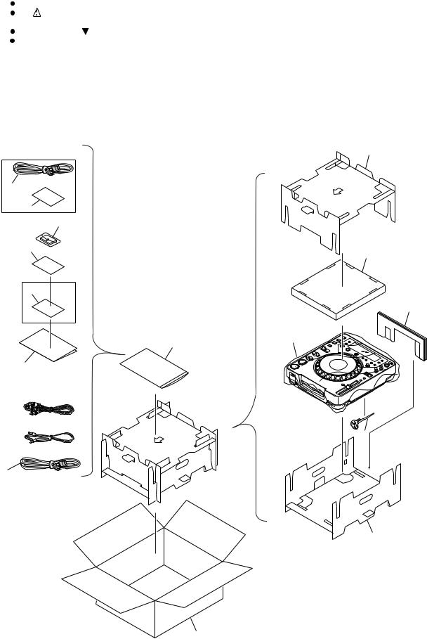
2.1 PACKING SECTION
B
TLFXJ only |
13 |
|
2
10
5
8
15
C
KUCXJ only 9
16
12
11
7
D
3 
6
4 
1 |
E
14
F
17
8 |
CDJ-1000MK3 |
1 |
2 |
3 |
4 |

5 |
6 |
7 |
8 |
(1) PACKING SECTION PARTS LIST
Mark No. |
Description |
Part No. |
|
> |
1 |
Power Cord |
See Contrast table (2) |
> |
2 |
Power Cord |
See Contrast table (2) |
|
3 |
Audio Cable (L = 1.5 m) |
VDE1064 |
|
4 |
Control Cord (L = 1 m) |
XDE3063 |
|
5 |
SD Memory Card |
DWX2622 |
|
6 |
Forced Eject Pin |
DEX1013 |
|
7 |
Operating Instructions |
See Contrast table (2) |
NSP 8 |
User Seat |
DRM1262 |
|
NSP |
9 |
Limited Warranty |
See Contrast table (2) |
|
10 |
Caution Card SB |
See Contrast table (2) |
NSP 11 |
Polyethylene Bag |
AHG7117 |
|
|
|
(0.06 x 230 x 340) |
|
|
12 |
Packing Sheet |
AHG7010 |
|
13 |
Pad (A) |
DHA1533 |
|
14 |
Pad (B) |
DHA1534 |
|
15 |
Pad (C) |
DHA1535 |
|
16 |
Pad (D) |
DHA1536 |
|
17 |
Packing Case |
See Contrast table (2) |
A
B
C
(2) CONTRAST TABLE
CDJ-1000MK3/KUCXJ, WYXJ5 and TLFXJ are constructed the same except for the following:
Mark |
No. |
Symbol and Description |
CDJ-1000MK3/KUCXJ |
CDJ-1000MK3/WYXJ5 |
CDJ-1000MK3/TLFXJ |
|
|
|
|
|
|
|
|
> |
1 |
Power Cord |
ADG7021 |
ADG1154 |
ADG1154 |
|
> |
2 |
Power Cord |
Not used |
Not used |
ADG7097 |
|
|
7 |
Operating Instructions (English) |
DRB1397 |
Not used |
Not used |
|
|
7 |
Operating Instructions |
Not used |
DRB1396 |
Not used |
D |
|
|
(English/French/German/Italian/Duch/Spanish) |
|
|
|
|
|
7 |
Operating Instructions |
Not used |
Not used |
DRB1398 |
|
|
|
(English/ Spanish/ Chinese) |
|
|
|
|
NSP |
9 |
Limited Warranty |
ARY7043 |
Not used |
Not used |
|
|
10 |
Caution Card SD |
Not used |
Not used |
ARM7064 |
|
|
17 |
Packing Case |
DHG2576 |
DHG2575 |
DHG2577 |
|
|
|
|
|
|
|
|
E
F
|
|
|
|
|
|
9 |
|
|
CDJ-1000MK3 |
7 |
|||
|
|
|
||||
5 |
6 |
|
|
|
8 |
|

1 |
2 |
3 |
2.2 EXTERIOR SECTION
A
Refer to
"2.3 CONTROL PANEL SECTION".
21
B
|
46 |
|
|
|
|
|
|
|
Refer to |
|
|
|
39 |
A |
"2.4 SLOT-IN MECHA. SECTION". |
||
|
8 |
|
|||
|
38 37 |
B |
|
||
|
|
M |
|||
|
36 |
|
|
||
|
|
|
16 |
||
|
36 |
2 |
C |
||
|
L |
||||
C |
B |
||||
|
D |
||||
|
|
||||
|
|
|
|||
|
|
|
|
46 |
|
|
38 |
|
|
38 |
|
|
|
|
|
E |
36 |
46 |
|
M |
|
|
|
|
|
|
|
|
|
|
|||
|
|
|
|
|
|
|
|
|
||
|
|
|
|
36 |
|
33 |
|
P |
|
|
|
H |
48 |
|
38 |
|
|
H |
|
|
46 |
18 |
46 |
F |
G 20 |
|
46 |
11 |
5 |
47 42 |
||
46 |
|
|
32 |
|
3 |
|
||||
|
|
|
|
|
|
|
|
42 |
|
|
D |
|
|
|
46 |
|
|
|
K |
|
|
|
|
|
|
|
|
|
|
|||
|
|
|
17 |
|
|
E |
|
|
||
|
|
|
46 |
|
|
|
|
|
||
|
|
|
|
|
|
|
|
|
|
|
|
|
|
|
I |
|
25 |
I |
|
|
|
|
|
|
|
|
|
J |
|
|
|
|
26 |
|
42 |
|
|
|
|
|
|
|
|
|
G |
|
|
B |
C |
D |
E |
|
F 45 |
||
|
K |
|
E
1
A |
34 |
46 46 |
46 |
14 |
|||
|
S |
|
46 |
|
|
|
 R
R
Q J
 9 19
9 19
45
F
44 |
44 |
|
44 |
10 |
CDJ-1000MK3 |
4
44
|
T |
|
|
45 |
|
46 |
35 |
45 |
|
||
|
|
|
|
|
35 |
46 |
28 |
|
46
46 22
N
10
24 43
O |
43 |
44 |
|
|
46 |
L 
40
30
|
|
|
46 |
|
T |
|
|
|
|
|
23 |
|
|
31 |
|
|
13 |
P |
12 |
|
Q |
|
|
|
O |
N |
|
A |
46 |
|
F |
M S |
|
||
46 |
15 |
||
|
7 |
|
|
27 |
|
45 |
4 |
|
|
|
|
|
|
R |
|
|
|
6 |
|
-NONCONTACT |
SIDE |
CONTACTSIDE |
44 |
|
|
29
1 |
2 |
3 |
4 |
|
|
5 |
6 |
(1) EXTERIOR SECTION PARTS LIST |
|||
Mark No. |
Description |
Part No. |
|
|
1 |
MAIN Assy |
DWG1591 |
|
2 |
SLMB Assy |
DWS1366 |
|
3 |
SDCB Assy |
DWX2558 |
|
4 |
MJCB Assy |
DWG1605 |
> |
5 |
SW POWER SUPPLY Assy |
DWR1409 |
|
6 |
15P Flexible Cable |
DDD1301 |
|
7 |
Earth Lead Unit/300V |
DDF1032 |
|
8 |
Connector Assy 3P |
DKP3751 |
|
9 |
Connector Assy 6P |
DKP3752 |
> |
10 |
Inlet Assy |
See Contrast table (2) |
|
11 |
Earth Lead Unit/300V |
PDF1104 |
|
12 |
Connector Assy |
PF04PP-Q12 |
|
13 |
Connector Assy |
PF06PP-Q15 |
|
14 |
Connector Assy |
PF09PP-B12 |
|
15 |
Connector Assy |
PF11EE-R15 |
|
16 |
Power Button |
DAC2314 |
|
17 |
Door Spring |
DBH1565 |
|
18 |
Card Spring |
DBK1295 |
NSP 19 |
Silicone Sheet D5 L |
DEB1456 |
|
|
20 |
Door Cushion |
DEB1780 |
|
21 |
Laser Caution |
See Contrast table (2) |
|
22 |
Dust Guard |
DEC2939 |
NSP 23 |
Rear Panel |
See Contrast table (2) |
|
|
24 |
Heatsink |
DNG1099 |
|
25 |
PCB Stay |
DNH2711 |
|
26 |
Shield Case |
DNH2712 |
|
7 |
8 |
Mark No. |
Description |
Part No. |
27 |
Earth Plate C |
DNH2715 |
28 |
Shield Box |
DNH2728 |
29 |
Bottom Plate |
See Contrast table (2) |
30 |
Blind Cap |
DNK4218 |
31 |
Chassis |
DNK4553 |
32 |
Card Door |
DNK4554 |
33 |
Card Holder |
DNK4555 |
34 |
Insulator Assy |
DXA2092 |
35 |
Earth Plate |
VBK1070 |
36 |
Damper |
CNV6011 |
37 |
Earth Spring |
DBH1398 |
38 |
Float Spring G5 |
DBH1494 |
39 |
Mecha. Plate |
DNH2339 |
40 |
Cord Clamper |
RNH-184 |
41 |
Binder (SKB-90BK) |
ZCA-SKB90BK |
42 |
DM Screw |
DBA1260 |
43 |
Screw |
BBT30P100FTB |
44 |
Screw |
BBZ30P060FTB |
45 |
Screw |
BBZ30P060FTC |
46 |
Screw |
BPZ30P080FTB |
NSP 47 |
Cord Clamper (069Z) |
ZCB-069Z |
48 |
FFC Guard |
DEC2586 |
A
B
C
D
(2) CONTRAST TABLE
CDJ-1000MK3/KUCXJ, WYXJ5 and TLFXJ are constructed the same except for the following:
Mark |
No. |
Symbol and Description |
CDJ-1000MK3/KUCXJ |
CDJ-1000MK3/WYXJ5 |
CDJ-1000MK3/TLFXJ |
|
|
|
|
|
|
|
|
> |
10 |
Inlet Assy |
DKP3754 |
DKP3753 |
DKP3753 |
|
|
21 |
Laser Caution (7L) |
DRW2308 |
DRW2308 |
Not used |
|
|
21 |
Laser Caution |
Not used |
Not used |
DRW2248 |
|
NSP |
23 |
Rear Panel |
DNC1765 |
DNC1758 |
DNC1766 |
|
|
29 |
Bottom Plate |
DNH2710 |
DNH2710 |
DNH2732 |
E |
|
|
|
|
|
|
F
|
|
|
|
|
|
11 |
|
|
CDJ-1000MK3 |
7 |
|||
|
|
|
||||
5 |
6 |
|
|
|
8 |
|

A
B
C
D
E
F
1 |
2 |
3 |
4 |
2.3 CONTROL PANEL SECTION
58
63 |
53 |
44 62
64
65 (2/2)
57
59 |
61 |
|
|
|
|
|
|
|
|
59 |
|
|
|
|
|
|
|
|
|
|
|
|
|
A |
I |
|
|
|
|
|
|
72 |
|
|
|
|
|
||
|
|
|
|
|
49 |
60 |
|
||
|
|
|
|
|
|
|
|
|
|
|
|
|
|
|
B |
|
|
|
|
|
|
|
5 |
|
3 |
72 |
|
48 |
|
|
|
|
|
|
|
|
|||
|
|
|
|
9 |
|
|
|
||
|
|
|
|
|
|
|
|
|
|
66 |
|
|
|
|
|
|
|
|
50 |
|
|
|
C |
|
|
|
|
|
|
|
|
|
|
|
|
|
|
|
|
|
|
K 72 |
|
|
|
46 |
|
|
|
|
|
|
|
D |
|
51 |
|
|
|
|
|
|
|
|
|
|
|
|
|
|
|
|
|
|
|
|
|
52 |
56 54 |
11 |
|
H |
|
|
|
|
|
65 (1/2) |
|
72 |
|
|
|
|
|
55 |
|||
|
|
|
72 |
|
|
||||
72 |
|
|
|
|
|
|
|
13 |
|
|
|
|
|
|
14 |
|
47 |
||
|
|
|
|
|
|
|
73 |
||
|
|
|
|
|
|
B |
72 |
||
|
|
|
|
|
|
|
|
||
|
|
2 |
|
|
72 |
|
|
|
G |
|
|
72 |
|
|
|
|
|
72 |
|
|
|
|
|
|
|
|
|
||
|
|
|
|
|
|
|
|
|
|
72
12 |
C |
|
72 72
 D E
D E
72
|
1 |
|
72 |
NON-CONTACT SIDE |
CONTACTSIDE |
|
1; Grease: GYA1001 (ZLB-PN397B) |
|
2; Lubricant Agent: (ZLB-HFD1600) |
12 |
CDJ-1000MK3 |
26
16
|
|
|
|
|
15 |
|
2 |
|
|
|
2 |
|
|
|
|
|
|
|
|
|
|
|
29 |
|
74 |
|
|
74 |
2 |
|
|
|
|
||
|
|
|
|
74 |
|
|
|
21 |
|
41 |
|
|
|
17 |
|
27 |
|
|
|
|
|
||
|
17 |
|
|
|
21 |
|
20 |
|
|
|
|
|
21 |
20 |
17 |
20 |
|
|
|
|
|||
|
|
F |
20 |
20 |
1 |
|
|
|
|
||
|
|
20 |
|
|
|
|
|
|
|
|
|
|
|
|
|
|
72 |
45 |
|
|
|
|
42 |
|
40 |
|
|
|
|
|
|
|
|
|
|
70 |
72 |
|
|
|
43 |
|
|
|
|
|
|
|
|
|
|
|
72 |
|
|
|
|
|
30 |
A |
|
|
|
|
|
72 |
|
|
|
|
|
35 |
|
|
|
|
|
|
|
19 |
|
72 |
37 |
|
36 |
72 |
|
74 |
24 |
|
|
||
|
|
|
|
|
||
|
71 |
|
|
|
|
|
|
32 |
|
|
|
25 |
|
72 |
22 |
|
|
|
|
74 |
|
|
L |
|
|
|
74 |
|
|
|
|
68 |
34 |
|
|
|
23 |
|
|
||
|
|
|
|
|
||
31 |
|
|
|
|
|
|
|
6 |
|
|
33 |
68 |
|
F |
|
|
|
|||
70 |
|
J |
|
|
8 |
|
|
|
|
E |
39 |
||
1 |
10 |
|
18 |
|||
|
|
38 |
||||
|
|
|
|
|
|
|
|
|
72 |
7 |
72 |
|
|
|
|
4 |
|
|
28 |
|
|
|
72 |
MJCB |
|
||
|
|
|
CN1504 |
|
|
69 |
|
|
|
|
|
|
|
1 |
2 |
3 |
4 |

|
5 |
6 |
CONTROL PANEL SECTION PARTS LIST |
||
Mark No. |
Description |
Part No. |
1 |
MFLB Assy |
DWG1606 |
2 |
SLDB Assy |
DWS1367 |
3 |
RSWB Assy |
DWS1368 |
4 |
JFLB Assy |
DWG1602 |
5 |
KSWB Assy |
DWS1365 |
6 |
JOGB Assy |
DWG1603 |
7 |
22P Flexible Cable |
DDD1302 |
8 |
25P Flexible Cable |
DDD1303 |
9 |
10P Flexible Cable |
DDD1304 |
10 |
Connector Assy |
PF04PP-B07 |
11 |
LED Guard |
DEC2932 |
12 |
Protect Cushion |
DEC2938 |
13 |
VR Stay |
DNF1663 |
14 |
Earth Plate P |
DNH2714 |
15 |
JOG Plate |
DAH2052 |
16 |
JOG Panel |
DAH2182 |
17 |
SW Spring 25 |
DBH1514 |
18 |
Gear Spring 200 |
DBH1525 |
19 |
Arm Spring |
DBH1566 |
20 |
SW Cushion HH48/2 |
DEC2538 |
21 |
Ring Cushion L24/2.0 |
DEC2958 |
22 |
Encoder Plate |
DEC2889 |
23 |
Protect Sheet |
DEC2945 |
24 |
FL Sheet |
DEC2946 |
25 |
Gear Plate |
DNH2713 |
26 |
JOG B |
DNK4068 |
27 |
SW Ring |
DNK4070 |
28 |
Adjust Plate |
DNK4178 |
29 |
JOG A |
DNK4556 |
30 |
JOG Holder 1000 |
DNK4558 |
31 |
Gear Arm |
DNK4559 |
32 |
Gear |
DNK4560 |
33 |
Smoother |
DNK4561 |
34 |
Gear A |
DNK4562 |
35 |
Joint Gear 1 |
DNK4563 |
36 |
Joint Gear 2 |
DNK4564 |
37 |
Joint Gear 3 |
DNK4565 |
38 |
Compressor Plate |
DNK4566 |
39 |
Cam Plate |
DNK4567 |
40 |
Sheet SW |
DSX1065 |
41 |
Roller A Assy |
DXB1825 |
42 |
JOG Stay Assy |
DXB1876 |
43 |
Roller B Asssy |
DXB1877 |
44 |
Rotary Knob C |
DAA1194 |
45 |
Slide SW Knob |
DAC1926 |
5 |
6 |
|
7 |
8 |
|
|
Mark No. |
Description |
Part No. |
|
|
46 |
Set Knob (HS) |
DAC1986 |
|
|
47 |
Set Knob (MT) |
DAC1987 |
A |
|
48 |
Set Knob (TIME) |
DAC1991 |
||
|
||||
49 |
Tempo Reset Knob |
DAC1993 |
|
|
50 |
Set Knob (MEMO) |
DAC1994 |
|
|
51 |
Set Knob (LOOP) |
DAC1995 |
|
|
52 |
Re-Loop Button |
DAC2347 |
|
|
53 |
Adjust Knob |
DAC2350 |
|
|
54 |
Eject Knob |
DAC2365 |
|
|
55 |
Mode Select Knob |
DAC2366 |
|
|
56 |
Set Knob (SC) |
DAC2368 |
B |
|
57 |
Slide Sheet 1C |
DAH2404 |
||
|
||||
58 |
Display Panel |
DAH2435 |
|
|
59 |
Ring Lens |
DNK3880 |
|
|
60 |
Tempo Lens |
DNK3882 |
|
|
61 |
Card Lens |
DNK3885 |
|
|
62 |
Eject Guard |
DNK3958 |
|
|
63 |
Control Panel |
DNK4568 |
|
|
64 |
Slide Knob |
DNK4656 |
|
|
65 |
Mode Lens |
DNK4701 |
|
|
|
|
|
C |
|
66 |
Set Knob (PLAY) Assy |
DXB1909 |
|
|
67 |
• • • • • |
|
|
|
68 |
Washer |
WA52D120D25 |
|
|
69 |
Screw |
BPZ20P100FTC |
|
|
70 |
Screw |
IPZ30P100FTC |
|
|
71 |
Screw |
BPZ20P060FTC |
|
|
72 |
Screw |
BPZ30P080FTB |
|
|
73 |
Flange Nut M9 |
DBN1008 |
|
|
74 |
Screw |
DBA1265 |
|
|
|
|
|
D |
E
F
|
|
|
|
13 |
|
CDJ-1000MK3 |
7 |
||||
|
|||||
|
|
|
8 |
||

1 |
2 |
3 |
4 |
2.4 SLOT-IN MECHA. SECTION
A
3 14
 2
2
|
22 |
|
24 |
21 |
12 |
10 |
13 |
|
2 |
|
|
|
|
23
B
16
17
|
18 |
|
|
MAIN |
|
|
|
|
CN603 |
C |
1 |
|
|
|
|
|
|
|
|
11 |
19 |
20 |
2 |
8 |
|
|
9 |
||
|
15 |
|
||
|
|
|
|
|
|
|
|
34 |
|
Refer to
"2.5 TRAVERSE MECHA. ASSY-S". 33 4
|
36 |
33 |
32 MAIN |
|
CN601 |
D |
32 |
6
36
1 |
|
|
MAIN |
|
25 |
CN604 |
|
|
|
||
|
|
|
|
|
MAIN |
|
|
C |
CN602 |
|
|
D |
|
31 |
|
|
|
|
|
|
5 |
|
|
E |
|
35 |
2 |
|
7 |
31 |
|||
27 |
|
|||
|
|
|
30 |
|
F |
28 |
26 |
|
||
|
29 |
30 |
|
|
|
14 |
|
CDJ-1000MK3 |
1; Dyefree : GEM1036 (ZLX-ME413A)
2; Grease: GYA1001 (ZLB-PN397B)
NON-CONTACT SIDE |
CONTACT SIDE |
1 |
2 |
3 |
4 |

|
5 |
6 |
7 |
8 |
SLOT-IN MECHA. SECTION PARTS LIST |
|
|
||
Mark No. |
Description |
Part No. |
|
|
1 |
SPCN Assy |
DWX2559 |
|
|
2 |
INSW Assy |
DWS1369 |
|
|
NSP 3 |
Slot-in Mecha. G11 Assy |
DXA2068 |
|
|
4 |
Traverse Mecha. Assy-S |
DXX2566 |
|
|
5 |
13P Flexible Cable |
DDD1299 |
|
|
6 |
26P Flexible Cable |
DDD1300 |
|
|
7 |
Connector Assy 2P |
DKP3769 |
|
|
8 |
Connector Assy 2P |
DKP3750 |
|
|
NSP 9 |
DC Motor S |
DXM1230 |
|
|
10 |
Clamp Spring |
DBH1374 |
|
|
11 |
Guide Spring |
DBH1375 |
|
|
12 |
SW Lever Spacer |
DEC2420 |
|
|
13 |
Drive Lever |
DNK3406 |
|
|
14 |
Main Cam |
DNK3407 |
|
|
15 |
Disc Guide |
DNK3478 |
|
|
16 |
Clamp Arm |
DNK3576 |
|
|
17 |
Eject Lever |
DNK3684 |
|
|
18 |
Lever AP |
DNK3835 |
|
|
19 |
Lever BP |
DNK3836 |
|
|
NSP 20 |
Worm Gear |
DNK3910 |
|
|
21 |
Loading Gear |
DNK3911 |
|
|
22 |
Drive Gear |
DNK3912 |
|
|
23 |
Loading Base Assy-S |
DEA1022 |
|
|
24 |
Clamper D4 Assy |
DXA2043 |
|
|
25 |
Inside SW Base |
DNK4236 |
|
|
26 |
Float Base G11 Assy |
DXB1793 |
|
|
27 |
Front Sheet |
DED1132 |
|
|
28 |
Vessel Cushion A |
DEC2852 |
|
|
29 |
Vessel Cushion B |
DEC2853 |
|
|
30 |
Vessel Cushion C |
DEC2854 |
|
|
31 |
Spacer POR (T3) |
DEB1566 |
|
|
32 |
Float Rubber D3 |
DEB1404 |
|
|
33 |
Float Screw |
DBA1286 |
|
|
34 |
Loading Motor Assy-S |
DEA1008 |
|
|
35 |
Screw 2 x 5 |
VBA1062 |
|
|
36 |
Screw |
IPZ20P060FTC |
|
|
A
B
C
D
E
F
|
|
|
|
|
|
15 |
|
|
CDJ-1000MK3 |
7 |
|||
|
|
|
||||
5 |
6 |
|
|
|
8 |
|

1 |
2 |
3 |
4 |
2.5 TRAVERSE MECHA. ASSY-S
A
12
B
 1
1
C
5
D
|
8 |
1 |
4 |
2
8
 2
2
E
SPCN
CN3103
13
F |
13 |
|
1
MAIN
CN604
10
Cleaning liquid (GEM1004)
Cleaning paper (GED-008)
3
7
11 |
9 |
|
|
|
6 |
11
4
1; Grease: GYA1001 (ZLB-PN397B)
2; Grease: GEM1007 (ZLB-PN948P)
16 |
CDJ-1000MK3 |
1 |
2 |
3 |
4 |

|
5 |
6 |
7 |
8 |
TRAVERSE MECHA. ASSY-S PARTS LIST |
|
|
||
Mark No. |
Description |
Part No. |
|
|
NSP 1 |
Stepping Motor |
DXM1227 |
|
|
NSP 2 |
Spindle Motor G11 |
DXM1231 |
|
|
NSP 3 |
04RM2 Pickup Assy R |
OWY8071 |
|
|
NSP 4 |
Skew Screw |
DBA1263 |
|
|
NSP 5 |
Skew Spring |
DBH1437 |
|
|
NSP 6 |
Joint Spring (J) |
DBK1261 |
|
|
NSP 7 |
Slider Spring G11 (J) |
DBK1262 |
|
|
NSP 8 |
Guide Shaft (S) |
DLA1918 |
|
|
9 |
Joint |
DNK3858 |
|
|
NSP 10 |
Mounting Plate G11 (J) |
DNK4307 |
|
|
11 |
Screw 04 |
VBA1092 |
|
|
12 |
Screw |
BPZ20P080FTC |
|
|
13 |
Screw |
BPZ26P080FTC |
|
|
A
B
C
D
E
F
|
|
|
|
|
|
17 |
|
|
CDJ-1000MK3 |
7 |
|||
|
|
|
||||
5 |
6 |
|
|
|
8 |
|
1 |
2 |
3 |
4 |
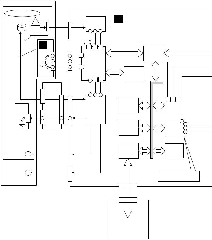
3.BLOCK DIAGRAM AND SCHEMATIC DIAGRAM
3.1BLOCK DIAGRAM
3.1.1 SIGNAL SECTION
A
B |
|
|
CN601 |
|
|
IC601 |
|
|
|
|
|
|
|||
SPINDLE |
|
|
|
|
|
FEP |
|
OEIC |
|
|
|
|
|
|
|
MOTOR |
|
|
|
14 |
18 |
29 |
|
|
|
|
|
|
|||
PICKUP |
B |
|
|
|
TE |
FE |
RFENV |
|
|
|
|
|
|
||
ASSY |
|
|
89 |
111 |
109 |
112 |
|
|
|
|
|||||
|
|
|
|
||||
|
CN2401 |
|
CN605 |
|
|
|
|
|
LPS1 |
|
|
|
|
|
|
|
S2401 |
1 |
175 |
|
|
|
|
SLMB |
1 |
|
|
|
|
||
2 |
|
2 |
|
IC603 |
|
||
ASSY |
|
|
SODC |
|
|||
|
LPS2 |
|
|
|
|||
|
|
|
|
|
|||
|
3 |
3 |
176 |
|
|
|
|
|
|
|
|
|
|||
C |
S2402 |
|
|
|
|
|
|
|
|
|
|
|
|
|
|
|
|
|
|
|
67 119 |
120 |
|
|
CN3103 |
|
|
|
LOAD |
FETRV |
TRDRV |
|
|
|
|
|
|
|
|
|
CN3102 |
CN602 |
|
26 |
53 |
52 |
|
|
|
|
|
|
|||
|
CN3101 |
|
|
|
|
IC602 |
|
CN3301 |
|
|
|
|
6CH DRIVER |
||
S3001 |
|
|
|
|
|
|
|
|
1 |
1 |
13 |
|
|
|
|
D
D |
|
|
|
C |
|
|
|
|
|
INSW ASSY |
SPCN ASSY |
|
|||||||
|
|
|
|
|
|
CN604 |
|
||
STEPPING |
M |
|
|
|
|
|
|
|
|
MOTOR |
|
|
|
|
|
|
|
||
|
|
|
|
|
|
|
|
||
TRAVERSE |
|
|
|
|
|
|
|
|
|
|
|
|
|
|
|
|
|
||
MECHANISM |
|
|
|
CN603 |
|
||||
LOADING M |
|
|
|
|
|
|
|
||
|
|
|
|
|
|
|
|||
MOTOR |
|
|
|
|
|
|
|
|
|
E
SLOT-IN
MECHANISM
F
A MAIN ASSY
SERIAL
ATAPI
IC301
FPGA
|
IC604 |
|
|
|
|
FLASH ROM |
|
|
|
|
IC103 |
|
|
|
FLASH ROM |
|
|
||
|
|
27 |
|
|
|
IC102 |
12 |
DATA |
|
|
4 |
|||
128MB SDRAM |
BCK |
|||
|
||||
|
|
14 |
||
|
|
|
||
|
IC403 |
IC401 |
|
|
SD CARD |
|
|||
DSP |
|
|||
CONTROLER |
|
|||
|
|
|||
|
|
SYSYTEM |
|
|
|
|
BUS |
|
|
|
|
Pitch bend |
|
|
|
SD CARD |
Key control at master tempo |
||
CN401 |
Generates CD digital out |
|
||
INTERFACE |
|
|||
CN3002
|
|
|
|
CN3001 |
|
E |
|
SD CARD |
|
|
|
CONNECTOR |
SDCB ASSY |
||
|
|||
|
|
|
|
18 |
CDJ-1000MK3 |
1 |
2 |
3 |
4 |
5 |
6 |
7 |
8 |
A
CN501
8
6
10
14
CN503
AUDIO
DATA
1 |
|
|
2 |
13 |
1 |
3 |
16 |
4 |
|
5
M SW POWER
L JOGB
SUPPLY ASSY
ASSY
|
|
|
|
|
|
|
D2201 |
|
|
|
|
|
|
|
|
|
|
|
ENCODER |
|
|
|
|||
|
|
|
|
|
|
|
|
|
|
SHEET |
|
|
|
|
|
|
|
|
CN2201 |
|
|
|
SW |
|
|
|
|
|
|
|
|
|
|
|
|
|
||
POWER |
POWER |
POWER |
|
2 |
1 |
|
|
|
|
|||
|
|
|
|
|
|
|
|
|
|
|
||
CN1501 |
|
CN1503 |
|
CN1507 |
|
2 |
1 |
|
|
1 |
|
|
|
|
CN2004 |
|
|
|
|
CN2003 |
|||||
|
|
|
|
|
|
JOG1 |
JOG2 ROTATION |
|
TCH |
|
||
|
F ASSYMJCB |
|
|
|
JOG |
|
|
|
||||
CN1502 |
CN1504 |
CN2002 |
|
DETECTION |
|
J |
JFLB |
|||||
|
|
|
|
|
|
|
|
|
|
|
ASSY |
|
8 |
|
|
|
|
|
|
|
|
|
V2001 JOGFL |
||
6 |
|
|
|
|
|
|
|
|
JOGFL |
|
|
|
|
|
|
|
|
|
|
|
|
CONTROL |
|
|
|
10 |
|
|
|
|
|
|
|
|
|
|
|
|
14 |
|
|
|
|
|
|
|
|
|
|
|
|
|
|
|
|
|
|
|
17 |
18 |
CN2001 |
|
|
|
|
|
|
|
|
|
|
19 |
|
|
|
||
|
|
|
|
|
|
|
17 |
18 |
19 |
|
|
|
|
|
|
|
|
|
|
|
|
CN1001 |
G ASSYMFLB |
||
ANALOG |
|
|
|
|
|
|
|
|
V1001 DATA FL |
|||
|
|
|
|
|
|
|
|
|
|
|
||
AUDIO |
|
|
|
|
|
|
|
|
|
|
|
|
1 |
|
|
|
|
|
|
|
|
|
|
|
|
4 |
|
|
|
|
|
|
|
|
|
|
|
|
|
|
|
|
|
|
6 |
26 |
25 |
27 |
|
|
|
|
IC1512 |
|
|
|
|
|
|
DATA FL CONTROL |
||||
|
OP AMP |
|
|
|
|
|
|
|||||
|
|
|
|
IC1001 |
|
|
|
|
||||
3 |
5 |
|
|
|
|
|
|
|
|
|||
|
|
|
|
FL UCOM |
74 |
|
|
|
||||
|
|
|
|
|
|
|
|
|
|
|
|
|
|
|
|
|
|
|
CN1007 |
LED KEY |
J1006 |
J1004 |
|||
|
|
|
|
|
|
|
||||||
1 |
7 |
|
|
|
|
|
|
|
|
|
2 |
|
|
|
|
|
|
|
|
|
|
|
|||
|
|
|
|
|
|
CN2301 |
|
|
|
|
|
2 |
L |
R |
|
|
|
|
|
|
|
|
CN1201 |
J1301 |
|
|
|
|
|
|
|
LED KEY |
|
LED |
|
|
S3001 |
|
JA1502 |
JA1503 |
|
JA1501 |
|
|
|
|
|||||
|
|
|
|
KEY |
|
|
|
|||||
AUDIO OUT |
DIGITAL |
|
CONTROL |
|
|
|
|
|
DIRECTION |
|||
|
|
OUT |
|
|
|
|
|
|
|
|
|
SW |
K |
TEMPO |
I |
ZERO ADJ. |
||
VR1202 |
||
KSWB |
H ASSYSLDB |
RSWB |
ASSY |
ASSY |
|
|
|
|
|
19 |
|
CDJ-1000MK3 |
7 |
|||
|
|
||||
6 |
|
|
|
8 |
|
B
C
D
E
F

1 |
2 |
3 |
4 |
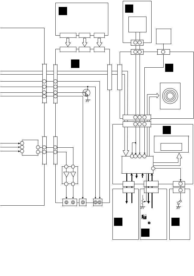
3.1.2 POWER SUPPLY SECTION
A |
|
|
|
|
|
|
|
|
|
|
|
|
|
|
|
|
|
AC CORD |
AC INLET |
|
|
|
|
|
|
|
|
|
|
|
|
|
|
|
|
|
|
|
|
|
|
CN201 |
|
|
|
|
CN601 |
|
A MAIN ASSY |
|
|
V+12S |
||
|
|
|
|
|
|
|
|
|
|
|
B |
PICKUP |
|
VA5V |
|
|
|
|
|
11 |
10 |
|
|
|
|
|
|
|
||||
|
|
|
|
|
|
|
|
|
||
|
ASSY |
|
5 |
|
|
|
|
|
CN1503 |
|
|
|
|
|
|
|
|
|
|
||
|
|
|
|
|
|
|
V+12S |
CN502 |
CN1501 |
|
|
|
|
|
|
|
|
|
|
||
|
|
|
|
|
|
|
|
1 |
1 |
|
|
CN3103 |
|
|
|
R609 |
|
|
|
IC1514 |
|
|
|
|
|
0 |
|
|
2 |
|
||
|
|
|
|
|
|
|
|
2 |
|
|
SPINDLE |
12 |
13 |
1 |
|
|
|
V+5S |
5 |
5 |
|
|
|
|
|
|
||||||
MOTOR |
|
|
|
|
|
|
|
|
|
|
|
|
|
|
VD3V |
|
|
V+3R3 |
7 |
|
|
C |
CN3102 |
CN602 |
|
|
|
|
7 |
|
||
|
|
IC606 |
|
|
|
|
||||
|
|
|
|
|
|
5V → 3.3V |
|
V+1R8 |
9 |
|
|
C |
|
|
|
R604 |
|
When V+5S is OFF, |
9 |
|
|
|
|
VA3V |
|
IC605 output becomes |
|
|
|
|||
|
|
0 |
|
|
|
|
||||
|
|
|
|
|
OFF. |
|
|
|
||
|
|
|
|
|
|
|
|
|
||
|
SPCN ASSY |
|
|
|
|
|
|
IC1513 |
|
|
|
|
|
|
When VD1R5 is OFF, |
|
|
|
|
||
|
|
|
|
|
|
|
|
|
||
|
|
|
|
IC606 output becomes |
Q601, Q602 |
|
|
|
|
|
|
|
|
|
OFF. |
|
1.5V → 5V |
|
|
|
|
|
|
|
|
|
VD1R5 |
|
|
|
|
|
|
|
|
|
|
|
IC605 |
|
|
|
|
|
|
|
|
|
|
3.3V |
→ 1.5V |
|
|
|
D |
|
|
|
|
V+2R5FPGA |
|
|
|
|
|
|
|
|
|
|
|
|
IC302 |
|
|
|
|
|
|
|
|
|
|
3.3V → 2.5V |
|
|
|
|
|
|
|
|
V+1R6TI |
|
|
|
|
|
|
|
|
|
|
|
|
IC405 |
|
|
|
|
|
|
|
|
|
|
3.3V → 1.6V |
|
|
|
|
|
|
|
|
V+3R3 |
|
|
|
|
|
|
|
|
|
|
|
When V+3R3 is OFF, |
|
|
|
|
|
|
|
|
|
|
IC303 output becomes |
|
|
|
|
|
|
|
|
|
V+1R2FPGA |
OFF. |
|
|
|
|
|
|
|
|
|
|
|
|
|
|
|
E |
|
|
|
|
|
|
IC303 |
CN503 |
CN1506 |
|
|
|
|
|
|
|
|
1.8V → 1.2V |
|
||
|
|
|
|
|
|
|
|
|
|
|
|
|
|
|
|
|
|
|
V+5A |
|
|
|
|
|
|
|
|
|
|
12 |
V+5A |
|
|
|
|
|
|
|
|
|
13 |
|
|
|
|
|
|
|
|
|
|
CN401 |
|
|
|
|
|
|
|
|
|
|
9 |
|
|
|
|
|
|
|
|
|
|
5 |
|
|
|
|
|
|
|
|
|
V+3R3 |
CN3002 |
|
|
F
20 |
CDJ-1000MK3 |
E
SDCB ASSY
1 |
2 |
3 |
4 |
5 |
6 |
7 |
8 |
A
M SW POWER SUPPLY ASSY
L JOGB ASSY
|
|
|
CN601 |
|
CN301 |
|
|
|
|
V+5D |
|
|
|
|
|
|
|
|
|
||
V+5 |
V+3R3 |
V+1R8 |
12A-V |
V+12A |
VLOAD |
FLAC4 |
FLAC3 |
FLAC2 |
FLAC1 |
CN2201 |
3 |
7 |
5 |
3 |
4 |
1 |
6 |
|
|
|
CN1505 |
|
CN1507 |
|
|
IC1507 |
V-12AJ |
|
IC1504 |
IC1502 |
|
|
|
|
|
IC1506
V+3R3
V+1R8
V+5D
VLED
F MJCB ASSY
|
IC501 |
|
V+12AJ |
|
12V → 5V |
|
|
|
|
|
|
4 |
3 |
2 |
1 |
3 |
CN2004
IC1503 |
IC1501 |
|
|
18 |
|
|
16 |
|
|
20 |
|
|
14 |
|
|
12 |
|
Q1507 |
22 |
|
41V → 27V |
||
|
||
|
1 |
|
|
8 |
FLAC1
 18
18
FLAC2
 16
16
VLDMFL
20
FLAC3
 14
14
FLAC4
 12
12
VLDJOG
 22
22
 1
1
 8
8
CN1504 |
CN2002 |
11 25
11 25
J1006
9 |
4 |
9 |
4 |
CN1201
VLED
V+5D
H
SLDB ASSY
J JFLB ASSY
V2001 JOG FL
CN2001
7 |
6 |
5 |
4 |
1 |
7 |
6 |
5 |
4 |
1 |
CN1001
V1001 DATA FL
G MFLBASSY
CN1007
9
9
CN2301
VLED
K
KSWB ASSY
|
|
|
|
|
|
21 |
|
|
CDJ-1000MK3 |
7 |
|||
|
|
|
||||
5 |
6 |
|
|
|
8 |
|
B
C
D
E
F
1 |
2 |
3 |
4 |
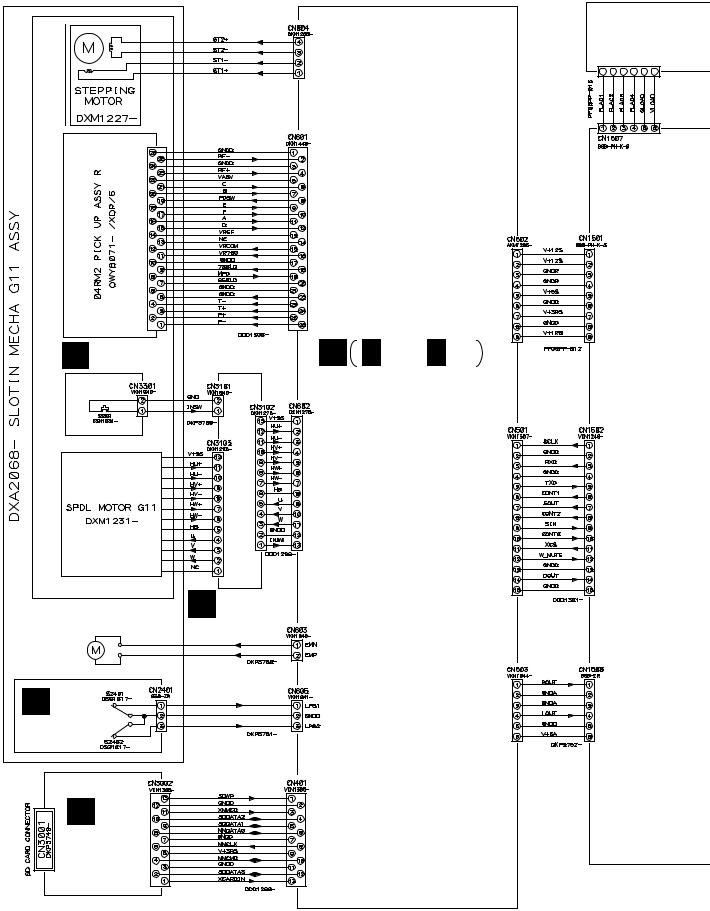
3.2 OVERALL WIRING DIAGRAM
A
B
C
TRAVERSE MECHANISM ASSY-S (DXX2566)
INSW ASSY D (DWS1369)
CN301
A A 1/4 - A 4/4
MAIN ASSY (DWG1591)
D
C SPCN ASSY (DWX2559)
LOADING
MOTOR
ASSY-S
DEA1008
E B
SLMB ASSY (DWS1366)
E
SDCB ASSY (DWX2558)
F
22 |
CDJ-1000MK3 |
1 |
2 |
3 |
4 |

5 |
6 |
7 |
8 |
INLET ASSY: |
AC POWER CORD: |
|
|
KUCXJ: ADG7021 |
|
||
KUCXJ: DKP3754 |
A |
||
WYXJ5: ADG1154 |
|||
WYXJ5, TLFXJ: DKP3753 |
|||
TLFXJ: ADG1154, ADG7097 |
|||
|
|
M SW POWER SUPPLY ASSY CN101 (DWR1409)
CN601 CN201
K KSWB ASSY (DWS1365)
B
SLDB ASSY
H (DWS1367)
F MJCB ASSY (DWG1605)
G MFLB ASSY
(DWG1606)
C
I RSWB ASSY (DWS1368)
D
J |
JFLB ASSY |
L |
JOGB ASSY |
(DWG1602) |
|||
|
|
(DWG1603) |
E
÷When ordering service parts, be sure to refer to "EXPLODED VIEWS and PARTS LIST" or "PCB PARTS LIST".
÷ The > mark found on some component parts indicates the importance of the safety
factor of the part. Therefore, when replacing, be sure to use parts of identical F designation.
÷: The power supply is shown with the marked box.
|
|
|
|
|
|
23 |
|
|
CDJ-1000MK3 |
7 |
|||
|
|
|
||||
5 |
6 |
|
|
|
8 |
|
1
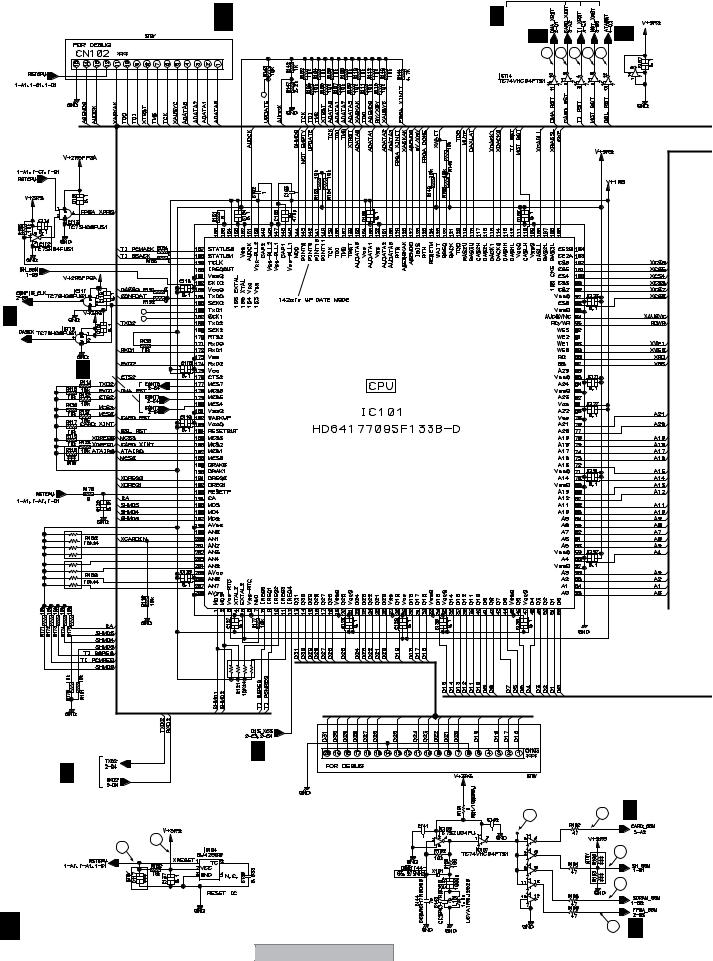
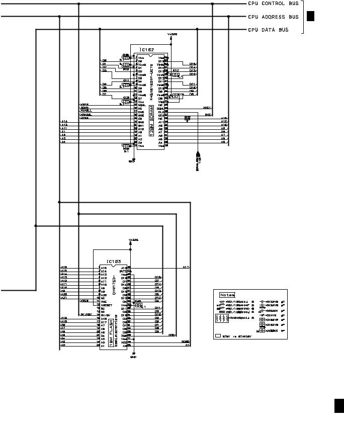
3.3 MAIN ASSY (1/4)
A
B
A 2/4
C |
A 2/4 |
D
E
A 2/4
1
2
F
A 1/4
24
2 |
3 |
A 1/4 MAIN ASSY (DWG1591)
A 2/4
CDJ-1000MK3
4
A 3/4 |
2/4 |
|
|
|
4/4 |
|
A |
|
|
|
A |
|
3 |
4 |
5 |
6 |
7 |
8 9 A 3/4
10
11
12 A 2/4
1 |
2 |
3 |
4 |
5 |
6 |
7 |
8 |
A
A 2/4, 3/4, 4/4
B
C
D
E
F
A 1/4
|
|
|
|
|
|
25 |
|
|
CDJ-1000MK3 |
7 |
|||
|
|
|
||||
5 |
6 |
|
|
|
8 |
|

1 |
2 |
3 |
4 |
3.4 MAIN ASSY (2/4)
A |
A 2/4 MAIN ASSY (DWG1591) |
|
|
13 |
|
|
A 1/4 |
|
|
A 1/4 |
A 3/4 |
B |
|
|
|
|
|
|
14 |
A 1/4 |
C |
|
|
|
|
A 1/4 |
|
A 3/4 |
|
|
|
A 1/4 |
D |
|
|
|
A 1/4 |
|
|
A 3/4 |
|
E |
|
|
|
A 1/4 |
|
A 4/4
F
A 2/4
26 |
CDJ-1000MK3 |
1 |
2 |
3 |
4 |
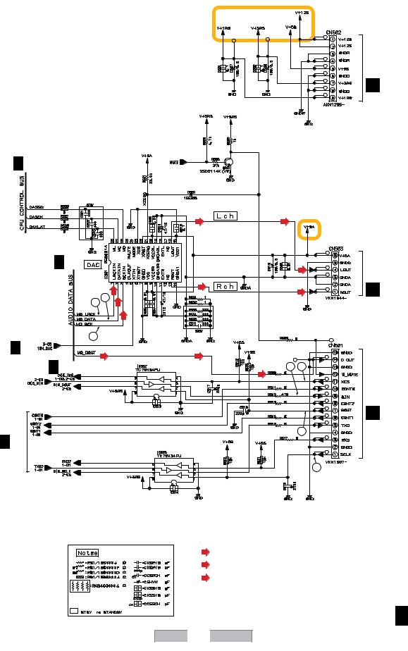
5 |
6 |
7 |
8 |
A
A 1/4
A 3/4
A 3/4
A 1/4
A 1/4
(DA)
15 16
17
(D)
(A) |
(A) |
(A)
(A)
(A)
(DA) (DA)
(D)
(D) |
20 21 |
19 
18
(DA)
: Audio Data Signal Route
(A)
: Analog Audio Signal Route
(D)
: Digital Out Signal Route
CDJ-1000MK3
5 |
6 |
|
|
|
7 |
F CN1501
B
C
F CN1506
D
F CN1502
E
F
A 2/4
27
8

1 |
2 |
3 |
4 |
3.5 MAIN ASSY (3/4)
A 2/4
A
A 1/4
|
|
1/4 |
A |
3/4 MAIN ASSY (DWG1591) |
|
A |
|||
|
|
|
|
|
|
|
|
|
|
|
CN3002 |
|
E |
B |
|
|
A 1/4 |
|
A 2/4 |
|
A 1/4 |
C |
|
D |
A 1/4 |
|
|
E |
|
F |
|
A 3/4 |
|
28 |
CDJ-1000MK3 |
1 |
2 |
3 |
4 |

5 |
6 |
7 |
8 |
A
|
|
|
|
B |
|
|
22 |
|
|
|
|
|
A 1/4 |
C |
|
|
|
|
|
A 1/4 |
|
|
|
|
A 2/4 |
(DA) |
(D) |
|
|
|
|
|
|
|
A 2/4 |
(DA) |
(DA) |
|
D |
|
|
|
||
|
|
|
|
|
|
27 |
|
|
|
|
|
26 |
|
|
|
25 |
A 2/4 |
|
|
|
A 4/4 |
|
|
|
23 |
24 |
|
E |
|
|
|
|||
|
(DA) |
: Audio Data Signal Route |
|
|
|
|
|
|
|
|
(D) |
: Digital Out Signal Route |
|
|
|
|
|
|
F
A 3/4
|
|
|
|
|
|
29 |
|
|
CDJ-1000MK3 |
7 |
|||
|
|
|
||||
5 |
6 |
|
|
|
8 |
|

1 |
2 |
3 |
4 |
3.6 MAIN (4/4) and SLMB ASSYS
A
B
C
D
E
TO PICKUP ASSY
C CN3102
|
|
43 |
|
|
44 |
|
|
(FS) |
|
|
(TS) |
|
|
32 |
|
36 |
37 |
|
|
|
|
|
38 |
(FS) |
(TS) |
|
(FS) |
|
|
|
|
(TS) |
34 (L) |
33 |
|
|
|
(L) |
|
|
|
|
(TS) |
|
|
|
(SP) |
(TS) |
31 |
|
30 |
|
(FS) |
|
|
|
(SP) |
(FS) |
|
|
TO LOADING |
35 |
|
(L) |
||
|
|
MOTOR ASSY-S |
||
|
|
(L) |
||
|
|
|
|
|
|
41 |
(ST) |
|
|
|
|
|
|
|
|
42 |
(ST) |
|
28 |
|
|
|
||
(SP) |
|
(ST) |
|
|
|
|
|
|
|
|
|
(ST) |
|
|
|
|
|
|
29 |
(SP) |
|
(ST) 40 |
|
TO STEPPING |
|
|
|
||
|
|
|
|
|
(L) |
|
(ST) |
|
MOTOR |
|
|
|
|
|
|
|
39 |
|
|
|
|
|
|
A 2/4 |
A 1/4
F
SLMB ASSY B (DWS1366)
A 4/4 B
30 |
CDJ-1000MK3 |
1 |
2 |
3 |
4 |
 Loading...