

Page 1
LPOR-304 Operating Instructions Revision A
LPOR-304
Dual Redundant Return
Band Receiver
Operating Manual
TEL: (209) 586-1022
USA: (800) 545-1022
FAX: (209) 586-1026
E-Mail: salessupport@ olson te c h.c om
www.olsonte ch.com
PAG E 1 o f
10
4 June 2006
Page 2
LPOR-304 Operating Instructions Revision A
Contents
DESCRIPTION ........................................................................................... 3
Front Panel .............................................................................................3
Figure 1 – LPOR-304 Front Panel ................................................................. 3
Rear Panel ..............................................................................................3
Figure 2 – LPOR-304 Rear Panel .................................................................. 3
Internal Adjustments................................................................................4
Figure 3 – Jumper Access Points .................................................................4
Control Board Layout................................................................................4
Figure 4 – Control Board Layout.................................................................. 4
Fuse.......................................................................................................5
Optical Input Chart...................................................................................5
Table 1 – Optical Input Chart.....................................................................5
LPOR-304 OPERATION OVERVIEW............................................................ 6
INSTALLATION ......................................................................................... 6
Table 2 – DIP Switch Settings .....................................................................6
OPTICAL BEHAVIOR .................................................................................7
Table 3 – Optical Thresholds......................................................................7
Function Switch .......................................................................................7
INDEPENDENT MODE DETAILED OPERATION............................................ 8
Rx1 and Rx2 LEDs (Independent)...............................................................8
Table 4 – Independent Rx1 and Rx2 LED Conditions ..........................................8
Mode LED (Independent) ..........................................................................8
REDUNDANT MODE DETAILED OPERATION ............................................... 8
Rx1 and Rx2 LEDs (Redundant) .................................................................8
Table 5 – Redundant Rx1 and Rx2 LED Conditions............................................. 8
Mode LED (Redundant).............................................................................8
Table 6 – Redundant Rx Mode LED Conditions .................................................8
OPTICAL POWER TEST POINTS ................................................................. 9
TEST POINT SELECT SWITCH .................................................................... 9
Table 7 – Test Point Select Switch Settings ....................................................9
I2C DISABLE LINES................................................................................... 9
SUMMARY ALARM RELAY .......................................................................... 9
Figure 5 – Microprocessor Block Diagram ..................................................... 10
PAG E 2 o f
10
4 June 2006
Page 3
LPOR-304 Operating Instructions Revision A
DESCRIPTION
The LP-OR-304 has dual, redundant return band receivers in a single module. The receivers have an
extended bandwidth of 300 MHz to allow the use of spectrum multiplication. Individual receivers in the
module can be disabled.
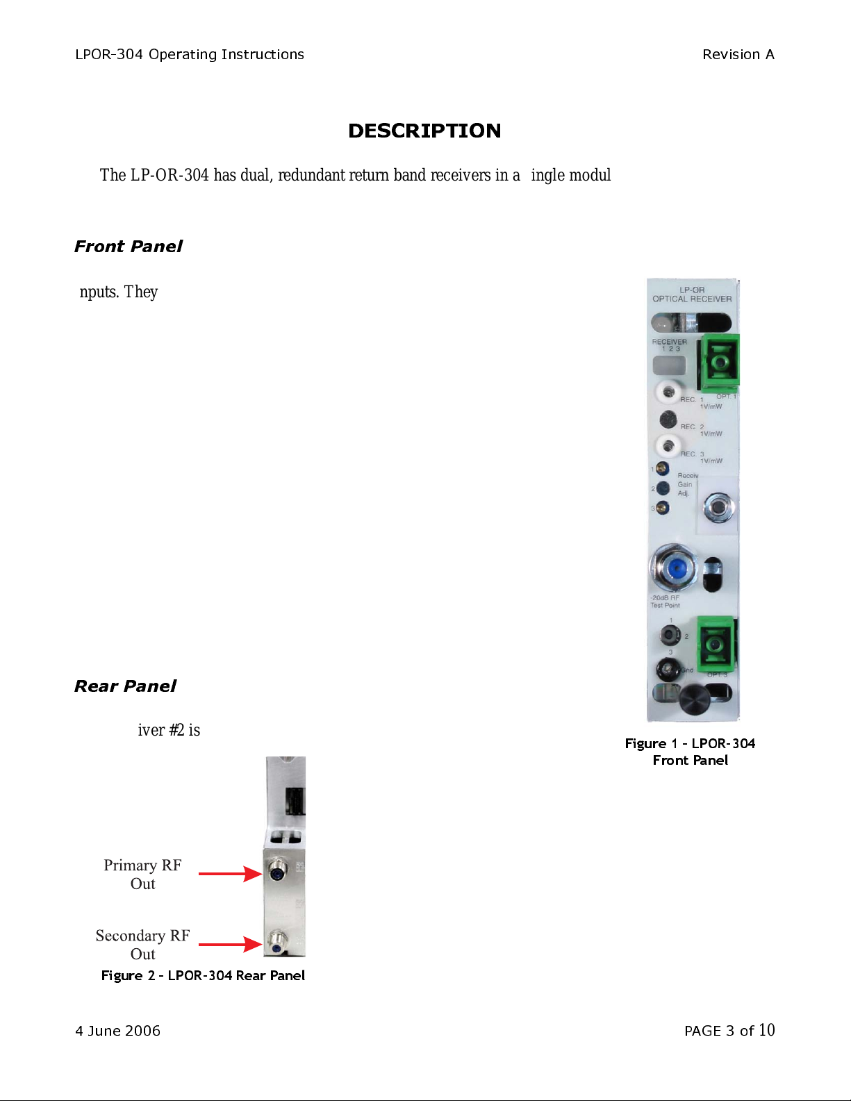
Front Panel
The two rectangular red/green status LEDs monitor the receivers’ optical
inputs. They are normally green and change to red on a low or missing optical
input. Any red LED causes a module alar m and a chassis summary alarm. The
two DC test points monitor the receivers’ optical inputs. One (1) mW ( 0 dBm)
is 1 V at the test point. Only high impedance meters should be used. Use the
ground test point at the bottom of the module, not chassis ground.
The two multi-turn potentiometers set the receivers’ gains. Setting any gain
control fully counter-clockwise will disable that receiver. A disabled receiver
will never generate an alarm.
The -20dB RF test point monitors the RF output of any single receiver. It
does not require termination.
The two position toggle switch selects which receiver’s output appears at
the test point. Ensure that this switch is in the correct position before using the
test point to set the RF gain.
The ground test point should be used when checking optical input levels.
The SC/APC optical input connectors are on the right of the front panel,
with optional FC/APC connectors available.
Rear Panel
The RF output connectors are on the rear of the unit. Receiver #1 is on the
top. Receiver #2 is on the bottom.
Figure 1 – LPOR-304
Front Panel
Figure 2 – LPOR-30 4 Rear Panel
4 June 2006 PAG E 3 of
10
Page 4

LPOR-304 Operating Instructions Revision A
Internal Adjustments
There are two jumpers that are accessible from the side that are used to set the receiver input range.
The jumpers can be changed with tweezers or needle nosed pliers. The nominal level for changing jumper
positions is -3 dBm.
Figure 3 – Jumper Acc ess Points
Control Board Layout
Figure 4 shows the locations of LPOR-304’s primary and secondary responsivity trim pots, the
programming DIP switch, and the fuse.
PAG E 4 o f
10
Figure 4 – Cont rol B oa rd Layou t
4 June 2006
Page 5

LPOR-304 Operating Instructions Revision A
Fuse
The module has an internal miniature 3A SB fuse in a holder. The Littelfuse part number is 0454003.
The Olson Technology P/N is 286-000009. See Figure 4, page 4 for fuse location.
Optical Input Chart
The following chart shows the test point readings versus optical input levels.
Table 1 – Optical Input Chart
T.P. Vo l ts
3.02 3.02 4.8
2.51 2.51 4
2.00 2.00 3
1.58 1.58 2
1.26 1.26 1
1.00 1.00 0
0.79 0.79 -1
0.63 0.63 -2
0.50 0.50 -3
0.40 0.40 -4
0.32 0.32 -5
0.25 0.25 -6
0.20 0.20 -7
0.16 0.16 -8
0.13 0.13 -9
0.10 0.10 -10
0.08 0.08 -11
0.06 0.06 -12
0.05 0.05 -13
0.04 0.04 -14
0.03 0.03 -15
Optical In pu t
(mW)
Optical In pu t
(dBm)
4 June 2006 PAG E 5 of
10
Page 6

LPOR-304 Operating Instructions Revision A
LPOR-304 OPERATION OVERVIEW
The LPOR-304 redundant receiver consists of two receiver boards, a switch board, and a status/
control board. The upper three LEDs are tri-color ones. The redundancy mode LED is visible through a
vent hole next to the Rx status LEDs. The unit can function as a redundant receiver or as dual
independent receivers.
A single pushbutton switch and an 8-position DIP switch control the major functions. See Figure 4,
page 4 for the switch location. The receiver gain controls will disable their receiver if fully turned CCW.
The status board has a microprocessor and two ADCs to monitor the optical input levels. The
microprocessor stores different responsivities for 1310 nm operation and 1550 nm operation. The voltage
read will be proportional to the optical power in mW. The microprocessor performs a 10*LOG10 function
to convert the mW value to dB m. All alarms and transfer decisions are based upon dBm levels. An 8position DIP switch, which is accessed by removing the left cover, sets all configurable parameters. All
alarm and display logic would be handled by the microprocessor. The user can select one of eight optical
switching thresholds via the DIP switch.
The microprocessor switches from the PRIMARY to the SECONDARY receiver in 50 ms or less
when the primary receiver indicates that it has insufficient light. The microprocessor also drives two
analog test points on the front panel via PWM outputs.
In the redundant mode, Rx1 is the PRIMARY receiver and Rx2 is the SECONDARY or BACKUP
receiver. In order to swap the fiber priority, the user must swap the input fibers.
INSTALLATION
The user must first set the DIP switches (SW1 on the 714 board) for the specific application (see
Figure 4, page 4 for location). The default factory shipping position for all switches is OFF. These
switches are read at least twice per second and updated when changes are sensed. T he eight switches
function as follows:
Table 2 – DIP Switch Settings
Switch
Number
1 Unit Mode Redundant Independent
2 Primary Input Wavelength 1310 nm 1550 nm
3 Secondary Input Wavelength 1310 nm 1550 nm
4 Optical Level Hysteresis Loose (3dB) Tight (1dB)
5 Restore Delay Instantaneous Delayed (60 Seconds)
6
7
8
Sets the Optical Switching Threshold in
the High to Low Direction
FUNCTION OFF ON
000 = -19 dBm
001 = -17 dBm
010 = -15 dBm
100 = -10 dBm
101 = -7 dBm
11 0 = -4 dBm
PAG E 6 o f
10
011 = -13 dBm
111 = -1 dBm
4 June 2006
Page 7

LPOR-304 Operating Instructions Revision A
OPTICAL BEHAVIOR
Six of the eight DIP switches (2, 3, 4, 6, 7, and 8) control the optical behavior of the unit. Switches 2
and 3 are used to set the wavelength of the two receivers. The user can select either 1310 nm or 1550 nm
independently for each channel. Switches 4, 6, 7, and 8 determine the optical input levels where the
receiver alarms switch. See Table 3 for details.
Table 3 – Optical Thresholds
Switch 6 Switch 7 S wi tch 8 Switch 4 Green to Red Thresho ld
OFF OFF OFF OFF -19 dBm -16 dBm
OFF OFF OFF ON -19 dBm -18 dBm
OFF OFF ON OFF -17 dBm -14 dBm
OFF OFF ON ON -17 dBm -16 dBm
OFF ON OFF OFF -15 dBm -12 dBm
OFF ON OFF ON -15 dBm -14 dBm
OFF ON ON OFF -13 dBm -10 dBm
OFF ON ON ON -13 dBm -12 dBm
ON OFF OFF OFF -10 dBm -7 dBm
ON OFF OFF ON -10 dBm -9 dBm
ON O FF ON OFF -7 dBm -4 dBm
ON O FF ON ON -7 dB m -6 dBm
ON ON OFF OFF -4 dBm -1 dBm
ON ON OFF ON -4 dB m -3 dBm
ON ON ON OFF -1 dBm +2 dBm
ON ON ON O N -1 dB m 0 dBm
Red to Green
Threshold
Function Switch
The pushbutton cycles through the following states by holding the button down for 0.5 second or
more:
• Automatic Mode (Redundant with Automatic Switchover)
• Force PRIMARY Rx Active
• Force SECONDARY Rx Active
(then cycle back to Automatic Mode)
The current state of the unit is stored in E2PROM in case of power failure. If power does fail, the last
valid state will be restored when power is restored.
4 June 2006 PAG E 7 of
10
Page 8

LPOR-304 Operating Instructions Revision A
INDEPENDENT MODE DETAILED OPERATION
Rx1 and Rx2 LEDs (Independent)
In the independent mode, the indivi dual receiver L EDs have three di splay sta tes. They will never be
orange.
Table 4 – Independent Rx1 and Rx2 LED Conditions
DISPLAY CONDITION
OFF Rx disabled
GREEN Rx input OK. Unit output from this Rx.
RED Rx input fault (Optical input is below preset threshold)
Mode LED (Independent)
In the independent mode, the mode LED blinks green for 0.25 second every 3 seconds to give an
indication that the unit is powered.
REDUNDANT MODE DETAILED OPERATION
Rx1 and Rx2 LEDs (Redundant)
The individual receiver LEDs have four display states. They blink to indicate an unacknowledged
fault on that input.
Table 5 – Redundant Rx1 and Rx2 LED Conditions
DISPLAY CONDITION
Off Rx Disable d v ia g ain c ontrol (Will nev er blin k )
Green Rx input Ok. Unit output from this Rx.
Orange Rx input Ok. Unit output from other Rx.
Red Rx input fault (Optical input is below preset threshold)
Mode LED (Redundant)
When operating as a redundant receiver, the mode LED has three display states. It is never turned off.
Table 6 – Redundant Rx Mode LED Conditions
DISPLAY CONDITION NOTES
Green
Primary Rx Input OK. Redundant
Operation Enabled.
Both receivers must be enabled. This state is
independent of the presence of backup optical input.
This can be from one of two causes:
Orange Redundant Operation Disabled
Red Redundant Operation Enabled
PAG E 8 o f
10
Either one or both receivers disabled with gain control.
Non-redundant operation selected with function switch.
Automatic transfer has occurred. Output of unit is
backup input whether or not optical signal is present on
this input.
4 June 2006
Page 9

LPOR-304 Operating Instructions Revision A
OPTICAL POWER TEST POINTS
The unit has two analog test points on the front panel, labeled REC.1 (T P1) and R EC.2 (TP2). These
voltages are generated by PWM outputs of the microprocessor. T he scale factor is such that the test points
give 1 Volt/mW of input light. Note that the microprocessor takes into account the wavelength in
generating these voltages. The wavele ngth causes the responsivity to va ry, changing the internal scaling
factor. Also note that these test points are in mW where other optical measurements mentioned herein are
in dBm. The step size for these outputs is approximately 33 µW.
TEST POINT SELECT SWITCH
This switch selects the RF monitor test point directly, not through the microprocessor. This switch
does not affect the output source of the unit. It has the same effect in redundant and independent modes.
Table 7 – Test Point Select Switch Settings
POSITION TEST POINT SOURCE
UP Rx1 (primary)
DOWN Rx2 (secondary)
I2C DISABLE LINES
There are two input lines from the I2C alarm circuit that are read at least twice per second. The inputs
and their function are as follows;
1) Alarm5 - This input (P2.2) determines if the Primary receiver is enabled. If Alarm5 is “OFF”, then
the Primary receiver is enabled. If Alarm5 is “1”, then the Primary receiver is disabled and the
Rx1 LED (D3) is turned off.
2) Alarm6 - This input ( P2.3) determines if the Seconda ry r eceiver is e nabled. If Alarm6 is “OFF”,
then the Secondary receiver is enabled. If Alarm6 is “1”, then the Secondary receiver is disabled
and the Rx2 LED (D4) is turned off.
SUMMARY ALARM RELAY
The P2.0 output of the microprocessor is used to drive a Summa ry Alarm Relay. When there are no
alarms and no receivers are disabled, this output s hould be a “OFF”. When there ar e any alarms and or
either receiver is disabled, this output should be a “1”.
Figure 5, page 10, shows a block diagram of all the microprocessor functions.
4 June 2006 PAG E 9 of
10
Page 10

LPOR-304 Operating Instructions Revision A
PAG E 1 0 of
10
Figure 5 – Microprocessor Block Diagram
END OF OPERATING MANUAL
4 June 2006
 Loading...